Bikernet Banner

Updating the Bikernet Experience

Hey, Here’s the deal. We’ve worked and spent an entire year to move all Bikernet Free Content (16,000 articles) onto a fast-acting, mobile-friendly, google accessible, WordPress Platform. ...
Read More

How to replace grips on a Harley-Davidson by J&P Cycles

Today, J&P Cycles shows you how to replace grips on a Harley Davidson motorcycle. From removing your old grips and adding new grips watch the entire process take place.In this video they use a 2013 Harley Davidson Softail Slim for demonstration but the process will be very similar for all motorcycles that utilize dual throttle cables.
Advertisement
Read More

Bikernet Project: Widowmaker Charity Build, Part 4

 
We are back at the Widowmaker Custom Design & Repair shop for final assembly of our bike. Everything has come back from paint, powder coat, etc. Now comes the patience part of our build, reassembly. At this point you need to have a plan of attack. Hopefully you took note of how you removed certain items so that your assembly is smooth without and scratches. Let us get started.
 
Item One: Where to start? I generally start by getting the bike back into a rolling state. But this can all hinge on your choice of engine. For Harleys and most v-twin engines this is the best approach. This is the way we approached our setup with the Yamaha Roadstar drivetrain. 
 
However, if you are working with an inline 4-cylinder metric engine you might want to come up with another approach. What I have done in the past is to lay the engine on the floor, on its side. Tape off the areas of your frame that will be near or possibly come in contact with the frame and lay your frame over the top of the engine, at which time you can install all your mounting hardware. This will make it easier to install the engine without damage to the painted surfaces; however it will make it more difficult to get the bike into a rolling state. 
 
One of the things people overlook is the proper set up of your fork bearing. I suggest going to the fork mfg. to get the proper bearing preload. However, a good rule of thumb is for your fall away to be 1 inch. Real easy to check. With your front end on bike and wheel installed and front of bike off the ground, simply move the front tire to a left turn position from center. From center to the point it starts to fall by itself without assistance should be 1 inch. Make sure you check left and right. Next is to tighten or loosen your triple tree stem bolt/nut until you get the desired results.

 
Item Two: Now is time for your driveline fitment. At this point I would suggest installing all the parts needed to complete your driveline. Start with your primary (if you are using an H-D unit). Alignment of your engine to transmission is critical. Once all is put together, chain/belt and brake install next.

 
One of the most common issues we see is improper wheel and brake caliper alignment. If your belt is not tracking true you will eat up belts. If you are using aftermarket calipers, it is critical that the caliper is centered over the rotor. You may have to shim your caliper to achieve this. If you don’t take the time to do this, the caliper and rotor can be damaged after a short period of time riding. Watch what brake fluid you use.. Know what the brake mfg. requirements are. Should be DOT 4 and DOT 5. In our case we were able to use all DOT 5 fluid.


Item Three: Now you’re ready to plumb the bike. Time to install your oil tank and remaining large items, such as your starter, headlight, etc. Plan ahead; you want your oil lines to be not only functional but appealing to the eye. Keep in mind that if you are using stainless steel braided hoses to make sure they are clear of any rubbing issues. A vibrating braided hose can become a saw on top of paint or aluminum. Do not put any fluids in your bike just yet; you may need to remove the tank for ease of wiring.


Item Four: Hands down, the largest area people struggle with is wiring. You can use a stock wiring harness, this works well if you are dealing with a metric bike as we did. However, be prepared to make modifications to the stock harness. I would suggest having a service manual for the brand of engine you are working with. This will make your life easier. If you are not and you’re planning on making your own harness, I would suggest owning a meter and have a clear understanding as how to use it.

I cannot stress enough to plan ahead.

 
The best way to handle this is by drawing up your own wiring schematic, making a list of all the items you are using. This will give you a visual to go by. In our case we used the stock wiring harness, with some modifications to make everything work. Then we added a great product, “Grip Ace.”

The “Grip Ace” makes for a super clean and simple install without the dopey look of stock switch housings. If you are not familiar with this product, visit them at www.gripace.com. This product allows you to have all of your bike functions literally at your fingertips of your left hand. The system is compiled of a four button key pad that is installed on your left hand grip and a slim line module that can easily hidden almost anywhere on your bike.

The wiring is super simple. Once your left hand grip is fitted with the key pad, run your preformed wire and plug through your bars and plug into the module. All of your bike functions are wired to the module. The unit comes with clean and clear wiring instructions and easy to follow schematics. On our bike, we chose to keep the system super clean and mounted our key pad to the inside tunnel of the gas tank. As for the rest of your wiring, test each circuit as you assemble it. Try not to rely on butt connectors, solder as many of your wire connections as possible and keep in mind the serviceability of the bike. Make sure that future removal of the headlight and rear fender can be done by unplugging the wiring rather than cutting it.

Item Five: Last pieces of the puzzle, installation of the tins. This can be the most rewarding part of the job, seeing your new bike in all its glory or it can be a bad day and a trip back to the painter. Make sure you take your time in this installation. Make good choices of hardware. I personally like to use rubber washers on painted surfaces so as not damage the paint with the installation of the mounting hardware. Once everything is hooked up, top off your fluids and add only enough fuel to get the bike running. I suggest this in case there is a an issue of a gas leak or oil leak that may require you to remove the tank. 

Once everything has checked out, get out and enjoy that first test ride. Make it short, come back, check everything over. Once all is good, pack up and enjoy your new ride.

Read More

Rebirth of an American Classic: Case Repairs

 
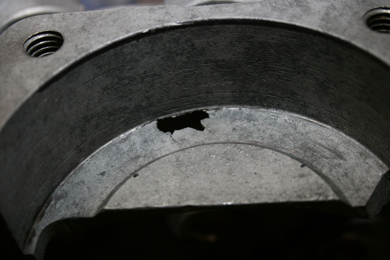
Before the engine could be rebuilt, the cases needed some additional work to repair a damaged portion of the front baffle.  It appears that an unknown piece of debris was wedged between the backside of the baffle and the flywheel which eventually knocked a hole right through the baffle.


Since HD engine cases are made from aluminum, the best method for repairing the hole was to use a TIG welder to fill in the missing material.  The hole was located at the thinnest portion of the baffle, so a piece of copper plate was used to cover the hole and provide support for the weld.


The entire case half was then placed in a parts oven set to 400 degrees Fahrenheit for 45 minutes.  This helped to bake out the old motor oil which had impregnated the case over the years and ensured that the entire case was at equal temperature for welding.  The heating also revealed that there were a number of cracks radiating out from the hole which also needed to be fixed.  By the time the hole, the cracks and the casting imperfections had been repaired, I was left with a good deal of weld to grind away.


The backside of the baffle was easy to reach and was ground back into shape with the help of a curved template and a flap wheel mounted to a hand drill.  The top of the baffle was much harder to grind with standard tools, so it was necessary to make a custom router bit using an aluminum sleeve epoxied to a ½” four fluted end mill.


Working slowly, I removed about 1/32” of excess weld with each pass of the router.  Liberal amounts of Teflon lubricant was used throughout the process.  After every pass the chips were removed and new lubricant was added to make sure no damage was caused by the aluminum sleeve riding against the case.


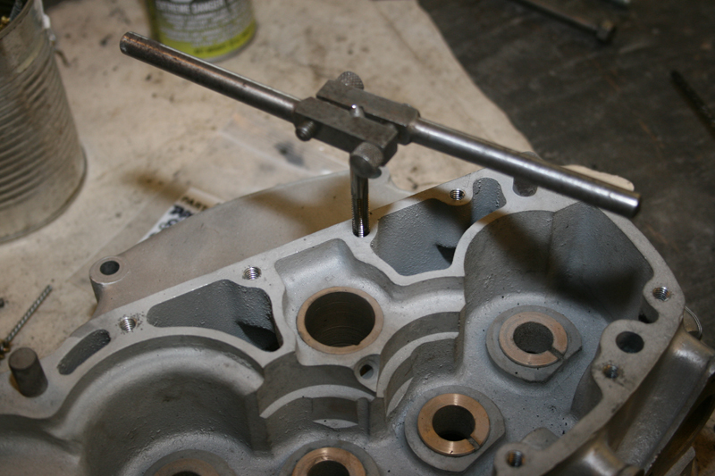
After some final shaping, the repair was complete and I moved onto chasing the threads for all the tapped holes.
 
 
Next, both case halves received a thorough cleaning.  All the holes were cleaned out with wire brushes attached to a hand drill to remove any aluminum chips and other debris.  From there the cases were soaked in warm soapy water and scrubbed with bristle brushes.  Then each case was carefully blown dry with compressed air, paying careful attention to blow out all holes and orifices.


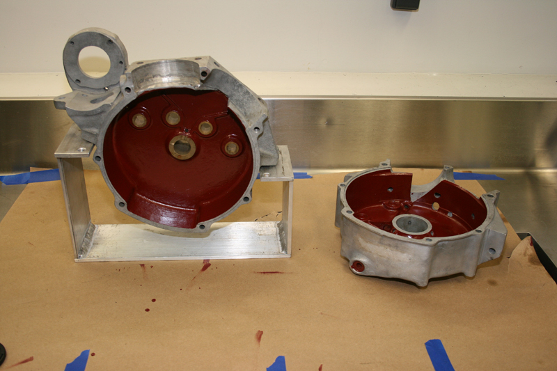
Once the cases were clean and dry, the last step was to apply a coat of Glyptal to the inside of both cases.  Glyptal is an enamel based sealer, so once it dries, it is tough to remove.  To insure that the sealer only coated the intended surfaces, each case half was carefully taped and covered.  Once the Glyptal was applied, it was cured in an over for two hours at 275 degrees Fahrenheit.  The result was a hard slick coat of Glyptal and a set of cases ready for assembly.


Editors Note:
If you would like to contribute to the completion of this bike please use the link below.
 
This project started on Black Friday of 2013 with just a set of engine cases and will end with a complete 1933 Harley-Davidson VL making a cross country run in the fall of 2014.  Already a great deal of progress has been made on the restoration of this motorcycle, but more funding is needed to see this project through to the end.  Additional articles will continue throughout the remainder of this build and will result in a complete digital archive which takes the reader through the restoration of a 1933 Harley-Davidson, step by step.  By making this information available freely online, future vintage motorcycle enthusiasts will be able to rebuild and maintain these great machines.

We have already gained the support of many of the top compaines in the vintage motorcycle industry.  If you would like to see your company’s logo included not only on the motorcycle, but also on every article, please contact me directly to learn more about our marketing campaign and advertising opportunities. EMAIL

 
Sponsored By


Read More

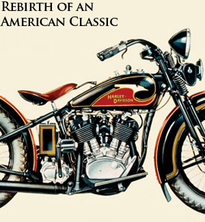
Rebirth of an American Classic: The Build Begins


After months of planning, my 1933 Harley-Davidson build officially started on Black Friday.  That’s when I made the long trip up to Replicant Metals (www.replicantmetals.com), located a mere 7 hours north of me in Pennsylvannia.  Owner Tom Feezer was waiting for me with a set of matched 1933 VL cases when I walked into the shop. These will serve as the basis for my build and are the most important part as the VIN number stamped on these cases is what makes the motorcycle a ’33 model. I plan to stay true to what the factory produced in ’33, but technically anything I build with these cases will be titled as a ’33 Harley-Davidson.
 
 
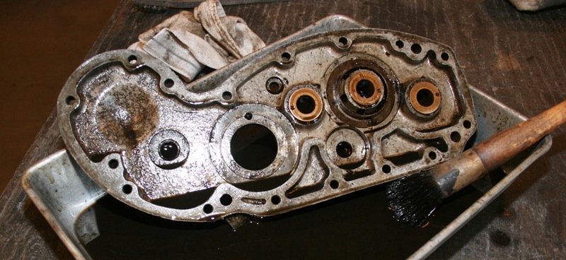
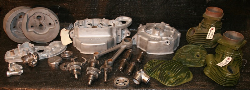
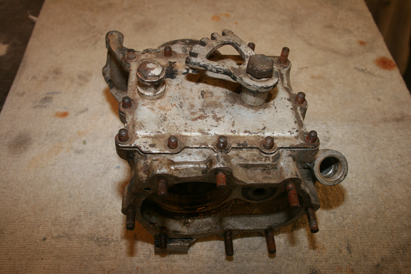
Setting aside the cases, I started making a pile of the other parts: heads, cylinders, cams, flywheels, rods and cam cover. Everything needed a trip through the blasting cabinet to knock off 80 years of built up grease and grime. Before loading up the blast cabinet, some of the parts needed to be broken down further, including the cases and the cam cover.  
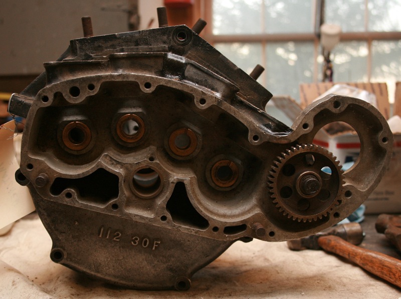
Starting with the cases, there were still some cylinder studs which needed to be removed.
 
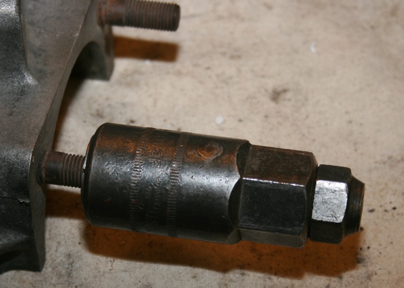
Normally, I’d just use the old two nut trick to back them out, but Tom actually had a specialty tool from Snap-On for removing them. The tool comes with a number of collets which are sized for different thread pitches and bolt diameters.  You screw the collet onto the stud and then slide a collar down over the collet. The opposite end of the collet in threaded on the outside, which allows you to screw a nut onto which forces the collar down the collet. As the collar slides down the collet, it tightens the collet onto the stud. Once the collet is secured onto the stud, you just unscrew the entire set up as one piece. The result is easy stud removal without damaging the stud or the case.
 
 
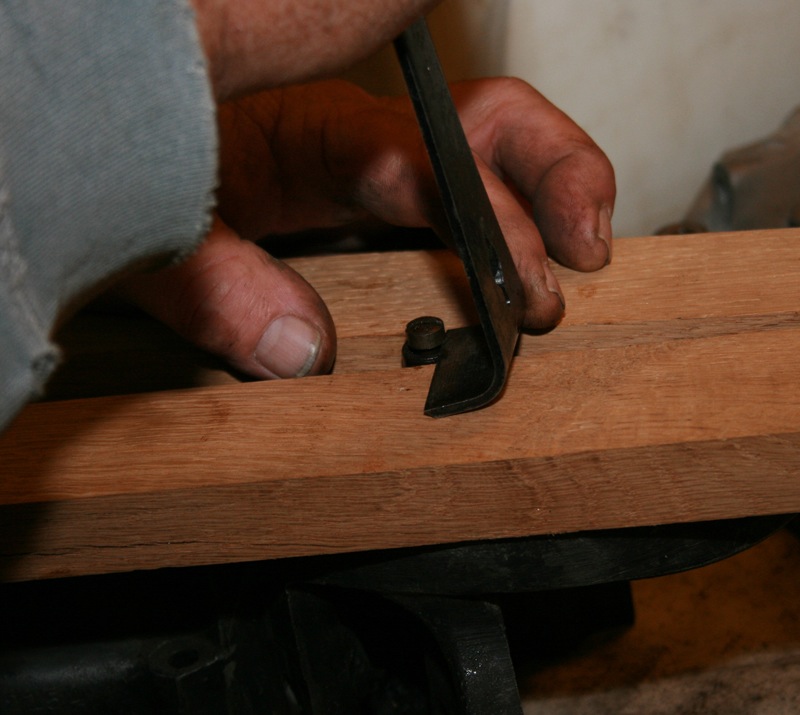
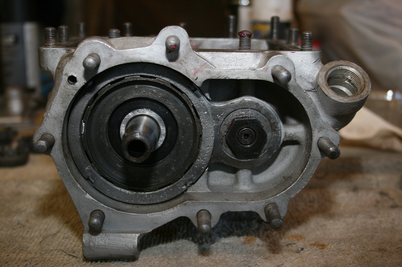
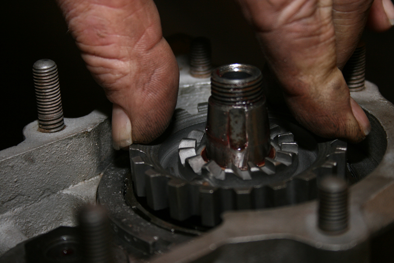
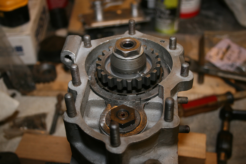
The idler gear and shaft also needed to be removed which was accomplished by first removing the retaining ring which keeps the gear on the shaft. After removing the retaining ring, the idler gear slid right off without any problems. The shaft proved to be a trickier to get out, but we were able to carefully pry it out after threading a bolt into the end of it.  Using blocks of wood to protect the case, a small pry bar was slipped under the bolt head to pry out the shaft.
 
 
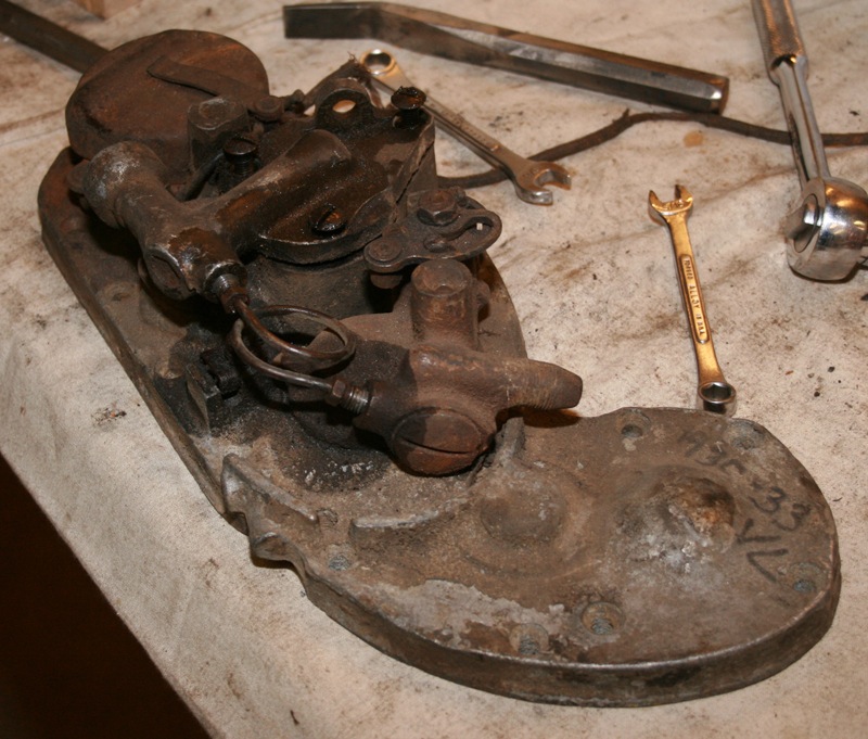
Next I turned my attention to the cam cover, which turned out to be the most complicated part to disassemble. Unlike modern motorcycles, the VL cam cover is used to houses the oil pumps and timer. All of these parts are held in with flathead screws, so special attention was paid not to damage them. The first step was to give everything a get soak in Kroil penetrating lubricant.
 
 
That did the trick for all but one screw. In the end, it took careful heating of the cam cover with a torch to break that last screw loose. These parts had enough surface grease on them that the needed to be cleaned in lacquer thinner to get them to a state suitable for putting in the blast cabinet.
 
 
Now I had enough parts to get started on the blasting process. The cabinet was filled with a fine grain aluminum oxide medium, which is gentle enough not to cause serious damage to the aluminum. Still, it was important to keep the gun moving back and forth to make sure that no one spot was cleaned to aggressively and to keep the overall color and surface texture even. As a precaution, I also taped over the VIN number just to make sure that it wasn’t damaged as well as plugging all the bushing holes.
 
 
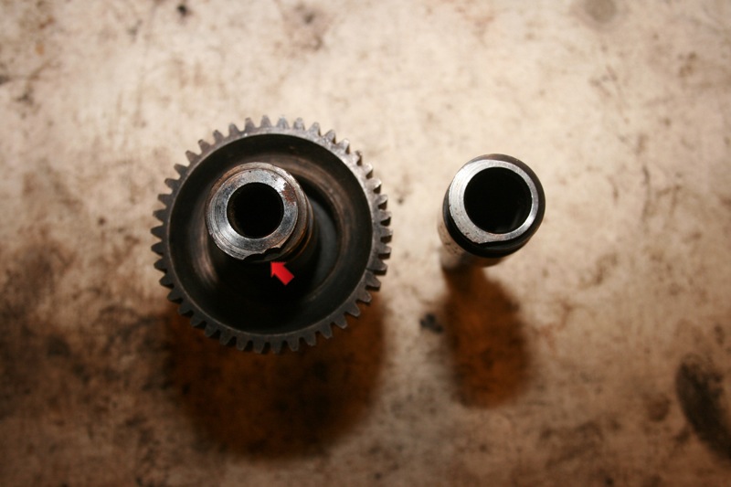
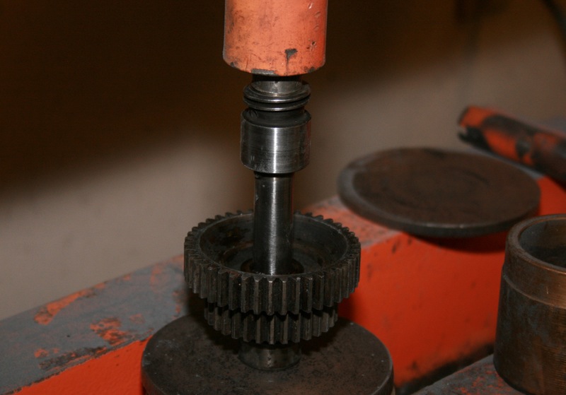
About half a day was spent blasting the cases, cam cover, oil pumps, timer parts, connecting rods and flywheels before I moved onto the cams. The V-series engine uses four gear driven cams, much like a modern Sportster, each cam as one lobe which opens either and exhaust or an intake valve. Upon close inspection of my cams, I discovered that the worm gear on cam #4, which drives the oil pump, was damaged.
 
 
This is an easy fix if you have a replacement shaft available. On V-series cams, the shafts are pressed onto the gear/lobe clusters, so to make this repair I just had to press out the damaged shaft and press in a replacement. Harley designed these cams with an alignment tab, so they can only be assembled in the correct orientation. 
 
 
When the repair was complete, the cams went into the blast cabinet to clean up the gears. I was careful not to blast any surfaces that would come in contact with the bushings in the case or cam cover.
 
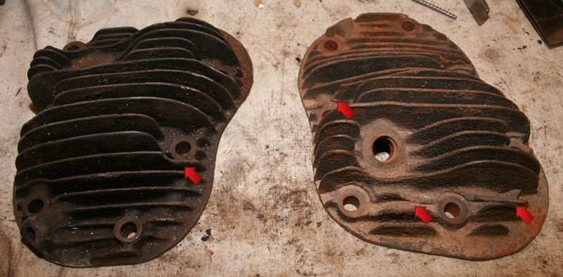
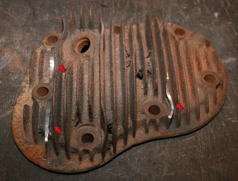
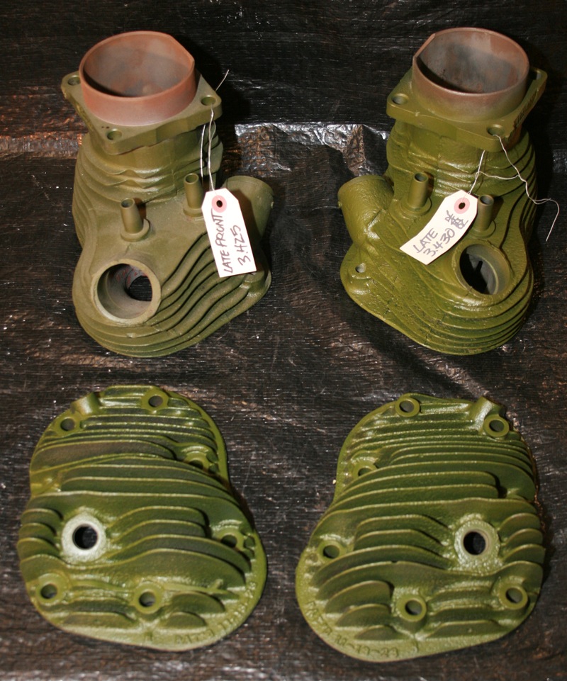
Lastly I turned my attention to the cylinders and heads. The cylinders were in good shape, without any broken fins and only bored .005” and .010” over stock. All they required was removing the old hi-temp paint from the external surfaces in the blast cabinet. The heads had some minor fin damage which is very common on flatheads. Fins can be easily snapped off when removing the heads if the wrong tool is used.
 
 
Since the damage to my heads was not extensive, I decided to use a die grinder to smooth out the broken fins. Once painted, they should blend together nicely and it will take careful inspection to spot the damaged areas. 
 
 
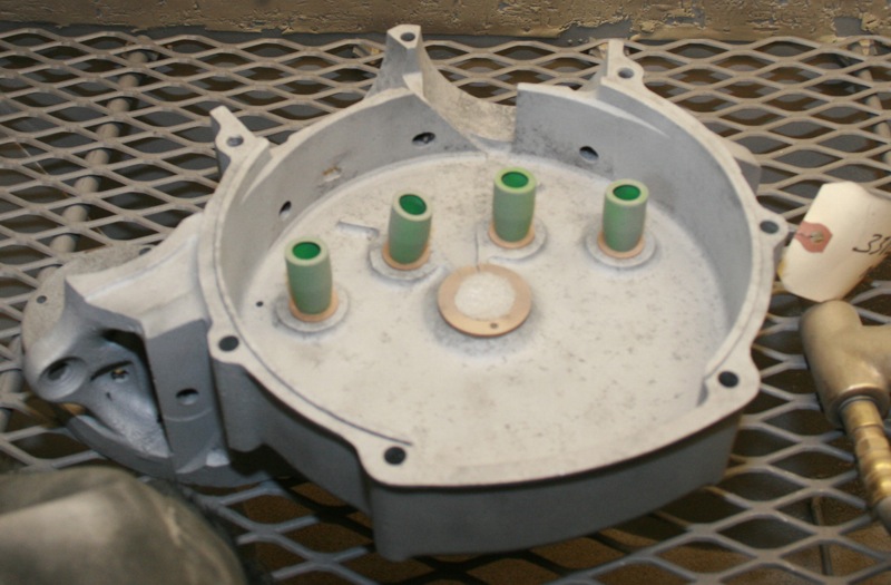
The heads were placed in the blast cabinet for final cleaning. To help protect my freshly cleaned heads and cylinders, they were all sprayed with an aircraft primer made by Tempo. Don’t be alarmed by the green color, they’ll get top coated black.
 
 
After a few pictures were taken, everything was boxed up to be sent out to the machine shop for inspection. After the machinist gives the ok on these parts, they’ll come back to the shop for a final cleaning to remove any debris left by the blasting process. Then it will be time to rebuild the engine.
 
 
Editors Note:
If you would like to contribute to the completion of this bike please use the link below.
 
This project started on Black Friday of 2013 with just a set of engine cases and will end with a complete 1933 Harley-Davidson VL making a cross country run in the fall of 2014.  Already a great deal of progress has been made on the restoration of this motorcycle, but more funding is needed to see this project through to the end.  Additional articles will continue throughout the remainder of this build and will result in a complete digital archive which takes the reader through the restoration of a 1933 Harley-Davidson, step by step.  By making this information available freely online, future vintage motorcycle enthusiasts will be able to rebuild and maintain these great machines.

We have already gained the support of many of the top compaines in the vintage motorcycle industry.  If you would like to see your company’s logo included not only on the motorcycle, but also on every article, please contact me directly to learn more about our marketing campaign and advertising opportunities. EMAIL


Sponsored By:


Read More

Bikernet Bike Build: BETSY’S REVIVAL STORY Part 2

 
     Oncethat trailer gate hit the driveway back at home I could see tired ol’Betsy begging for another chance at life! As I walked aroundthe trailer she lay resting after the 1500 mile journey back. Iassessed the impending task of making this Ol’ girl right again.
 
“Rode hard and put up wet,” I said to myself thinkingof all the journeys and adventures she served Scooter Tramp Scotty through.As I took in every line every worn out part of this soul servingmachine I tried to imagine all the places she saw, all thelandscapes, the women who made passenger, the endless white lines stretched for over half-a-million miles. The nomadicvessel of freedom that is this motorcycle I now have the honor ofsorting out to make whole again.
 
 
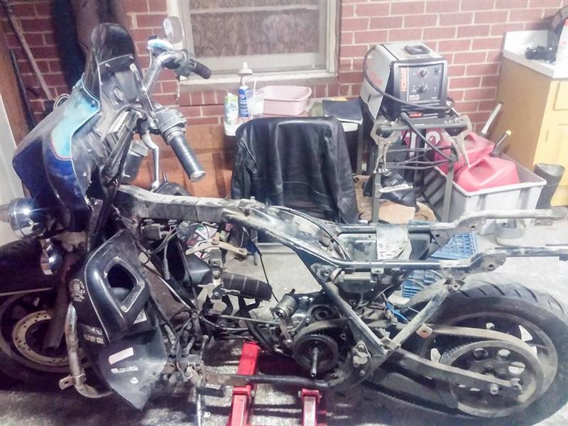
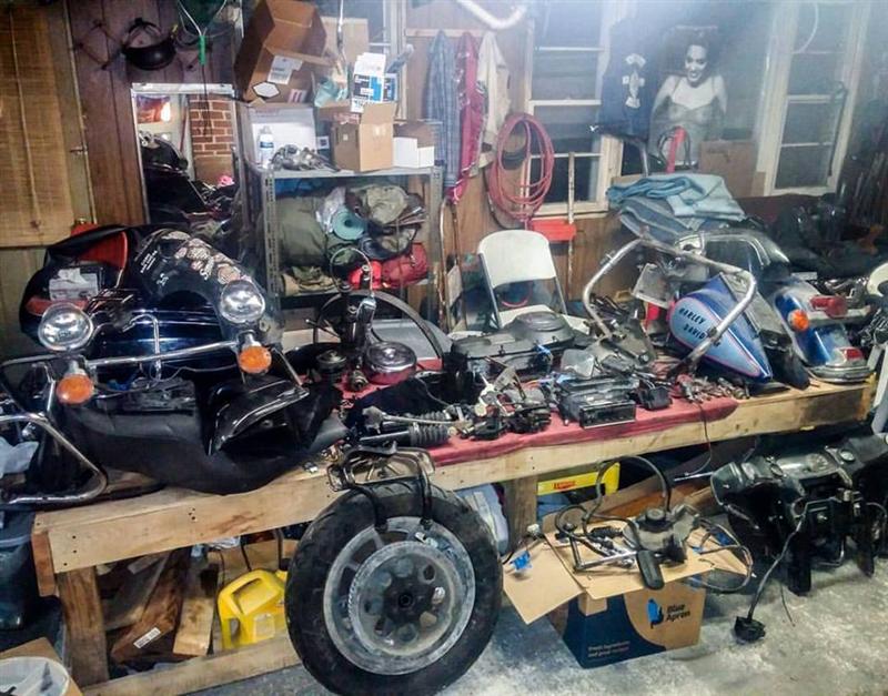
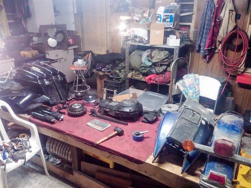
     Ilugged the broken pieces of this ’88 Electra Glide into the garageone by one. With an enthusiastic fire burning inside that I’vebecome a master at harnessing, I went straight to rearranging the shop foraccommodation of the new project. The work bench was clearedand the sorting of parts began, one-by-one. The bike “formallyknown as” Betsy quickly became a shell of her former self.The quest to get to her skeleton was my frantic goal, because there iswhere the worst lie waited to be healed. The evening faded to nightquickly and sleep was beckoning.

Tomorrow would be a new daybut with it came the disruptive chore of work so Betsy would laywaiting for my 6:30 return from the daily grind.
 
 
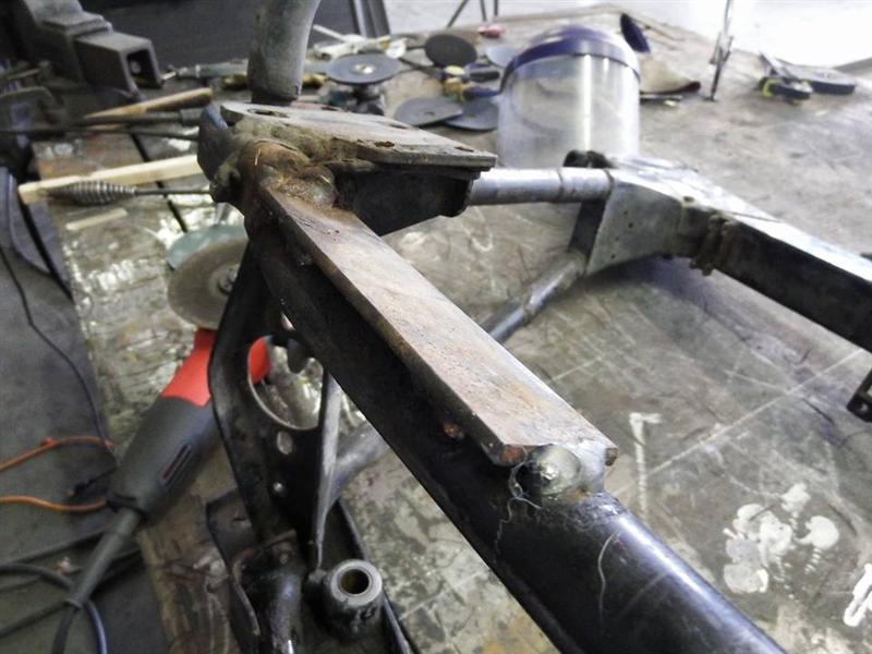
    Ipulled in to the house with anxious anticipation to strip her down tothat rusted and broken frame.As all parts lay categorized on the bench, I was left staring at 20years of grease and road grime thicker than the remaining paint theMoCo laid down 29 years prior. Before I could send this frameto repair, I had to get the layers of gunk off.
Thoughtsimmediately flooded my mind of just how many states and how manycountries this dirt belongs to! As I started scraping andcompiling clump by clump into the jar my imagination raced again intothe tapestry of visions stretching from Panama to Alaska where thistrusty companion carried her rider faithfully. I was holding inmy hand crust of the earth scooped up by Scooter Tramp Scotty’s gypsyjourneys traversing the entire North American continent for twodecades. WOW!
 
 
    Nowof course you know all of this has been documented in picturesthrough social media and through that incredible juggernaut I wasable to reach. I announced toFacebook land my intentions with Betsy and the response wasoverwhelming. This resurrection would only be possible withhelp of the great people who reached out to aid in thisreconstruction.
With the frame in real bad shape, it became my first and most important part of the restoration. An unsuspecting buddy reached out to me.Little did I know, he had been following the unfolding of theRevival of Betsy. Mr. Steve Brownell of Brownell Metal Studio, who has been a great friend of mine for a number of years extendedhis professional welding expertise. You see Steve has been inmetal manipulation for over 30 years doing high-end architectural andstructural work for some of Virginia’s finest establishments. Amaster welder and fabricator in every type of metal from brass,stainless, bronze, aluminum and steel, his craftsmanship is upperechelon in the industry.

     Bringingthis exhausted carcass to his hands of healing was a no brainer.I asked Steve, “Can you fix her road ravaged frame, brother?”He smiled ear to ear responding, “Of course I can.””I’ll have her back together better than the day sherolled off the assembly line.” My confidence in thisrevival mirrored the words from Steve’s mouth at that moment. Iknew this was the beginning of Betsy’s second coming!
 
 
     Stevewasted no time in tackling the task. Explaining to me how he had been followingScotty’s adventure, as many have, he was piqued by the ScooterTramp’s offbeat lifestyle and was excited to be a part of Betsy’srebirth. First line of business was tobead blast every square inch of the frame to expose any unseen rot or cracks laying camouflaged beneath the patina’d paint. Steve went towork uncovering what would soon become a little more than a brokenframe rail.
 
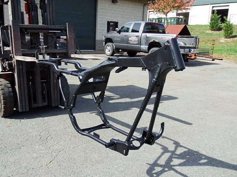
With three portions of the frame cracked and thebottom section of the frame rails looking like Swiss cheese, Stevecut out the cancered sections and replaced those portions withupgraded stainless steel meticulously melding the two metals togetherin one seamless blend of strength and integrity that won’t see rustagain at least in those portions. Hand shaping a few new panelsto replace and reinforce the swingarm junctures and a kickstand mountready for another twenty years of parking lot profiling, restorativefabrication COMPLETE!
 
Mr. Brownell even offered, as an addedbonus, to give her a two coats of primer, a fresh coat or three ofpaint, and shine her up with plenty of clear. She will onceagain be the prettiest girl at the ball or rally. I only sawthe process in pictures as you are now, but all I can sayis..AMAZING! Putting thirty plus years of quality experiencebreathing new life into a piece of true biker Americana, SteveBrownell, executed flawlessly.
 
 
     Igot the call about a week after drop off– the surgery was asuccess. The following morning I anxiously drove out toBrownell Metal Art Studio anticipating the unveiling of Betsy 2.0.Upon arrival I had that knot in my stomach as if meeting a girl forthe first time..fucking motorcycle..it was like the morning ofChristmas as a child all over again.
 
As I walked into the shopSteve met me upon entering with a shit eating grin, I knew it wasgoing to good. I said to him, “I see things went well.”
 
He replied, “Piece of cake.”
 
We walked over to theother half of the shop and lying in the middle of the floor restingon a piece of cardboard as to preserve the fresh paint from beingdamaged, sat the old girl. At first glance, I searched for arusted worn out hunk of metal until my gaze fell upon the gleam ofthe newly painted frame sparkling under the shop lights.
 
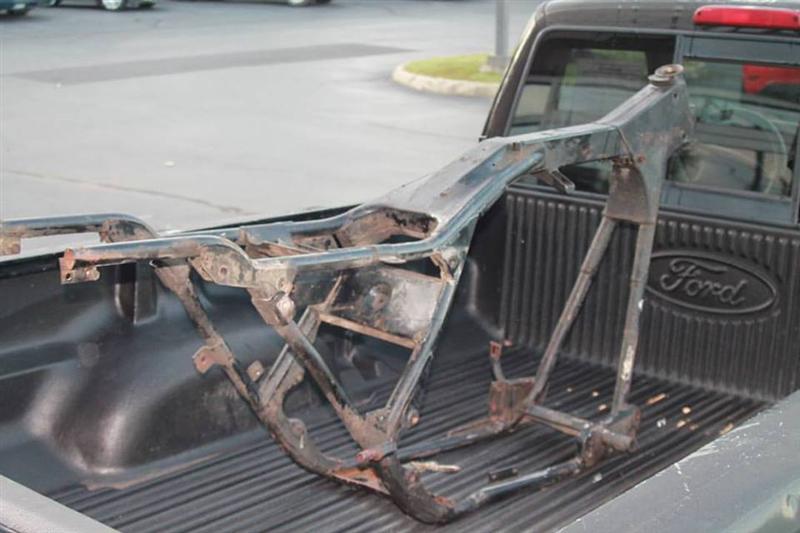
HOLYSHIT!..I couldn’t believe what I was seeing I had to double take.As I walked over to inspect Steve’s handy work I looked back at himreciprocating the same “shit eating” grin. I wasfloored. Having to remind myself that this is indeed the samerusted wore out tubes of iron I dropped off a week earlier. Wetook our time and carefully loaded the fresh chassis into the truckmaking sure all was secure and photos were taken.

      Ahuge expression of gratitude goes out to my friend Steve Brownell forselflessly donating his time and materials to bring this GypsyMachine back from the dead. As a fellow biker himself Stevereiterated to me a manta I hear and have used time and again, “That’swhat we do, brother.” With a new lease on life I closedthe tailgate behind the NEW girl, gave Steve a big appreciative hug,then drove off waving as I watched Steve and the crew in the rearview sending us on our way to future adventures yet to come.
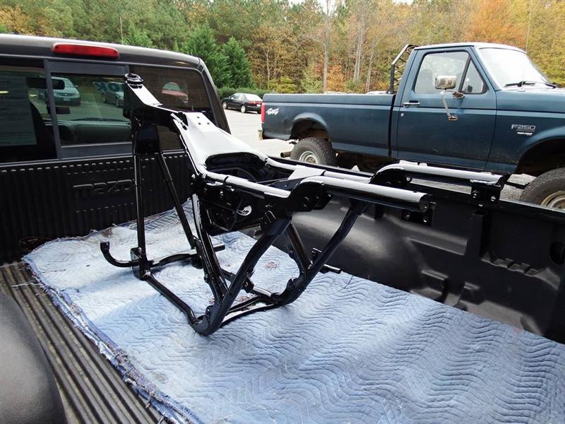
 
 
     Onthe ride back home I glanced behind me whispering, as if that framewas my girlfriend, in no time she will feel whole again.
 
“She’s a cheating Bitch,” Scotty.
 
Read More

Doug Coffey’s RetroMod Panhead Part 5


Back in the sixties the movie Wild Angels came out shortly followed by a soundtrack album with a great cover
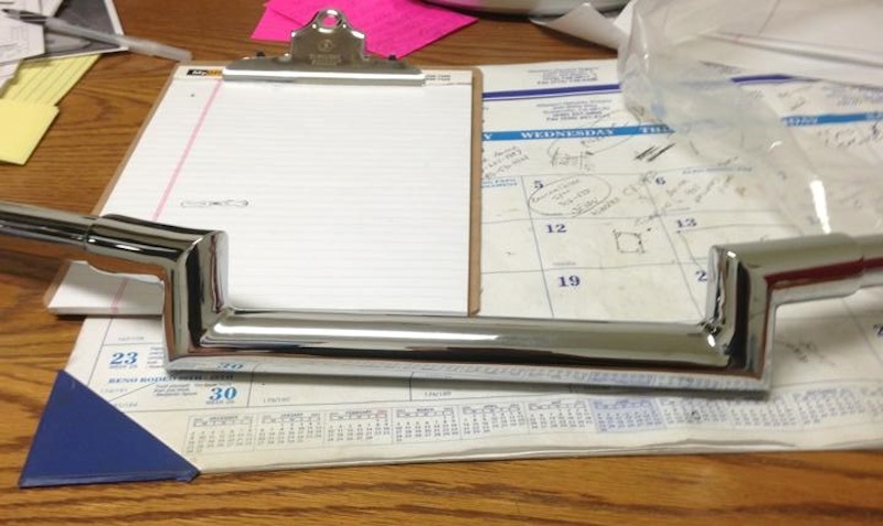
One of the bikes on the cover caught my eye. The one to the right of the lead bike has a set of low rise Zee style handlebars. Try as I might I could never find a manufacturer low rise Zee bars. Everything available was four inch rise or higher and it is still the same today.
I decided I would make my own Zee bars for this new bike project.
I wanted a beefier look for my handlebars than the usual one inch diameter so I used 1-1/4 inch DOM tubing and cut the pieces to size on my milling machine.
 
 
I made the end pieces from one inch tubing and after welding everything together I finally had some 1-1/2 inch low rise Zee bars
 
 
My good friend Ron McBroom from Paughco offered to chrome plate my bars for me and I think he did a darn fine job.

Risers


I wanted handlebar risers that looked just like original Glide risers but I had a problem. Original Glide risers are made for one inch handlebars and my bars were 1-1/4 inch which is 25% larger.
I wasn’t going to let that stop me so I made a drawing of the original Glide risers scaled up 25% larger.
After boring and tapping a hole to 1/2 x 13 threads per inch for mounting, I bolted them into an angle plate on my mill and bored a 1-1/4 inch hole for the bars.
In the picture at right you can see a stock original Glide riser.


After boring the holes for the bars on my milling machine the risers went back on the lathe for turning.
The left picture shows the turning work done including a guide groove for slitting the caps off later on the mill.
The right picture shows the finished product ready for polishing. I also drilled and tapped the holes for the Allen bolts on the milling machine.


I don’t much care for rubber mounted handlebars so I turned some mounting adapters on my lathe.


Mission accomplished.
(it only took me 45 years to get around to doing this)
Read More

Rebirth of an American Classic: Transmission Rebuild

 
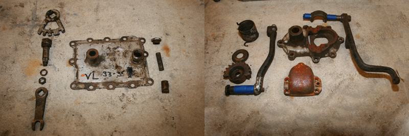
My 3-speed transmission started out very similar to my engine, an empty case and a pile of parts, all in need of cleaning.  So the first step was to break everything down into individual pieces and perform a thorough inspection of each piece, to see which parts just needed cleaning and which parts needed repairs or replacement.
 
 
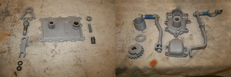
Luckily most of the parts were in good shape, even the transmission studs, so everything was put into the blasting cabinet.  It’s always important to note that you don’t want to blast bearing surfaces and fine threads, so these areas need to be covered before the part goes into the blast cabinet.  After a couple of hours of blasting, the results speak for themselves.
 
 
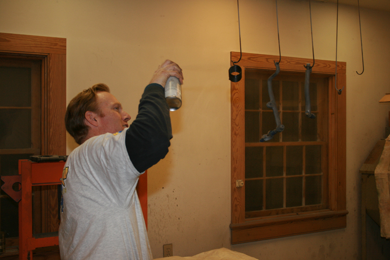
Next a coat of paint was sprayed on all the external parts (except the case).  Some parts were Cadmium plated from the factory, but a layer of silver paint was a quick way to approximate the original finish.
 
 
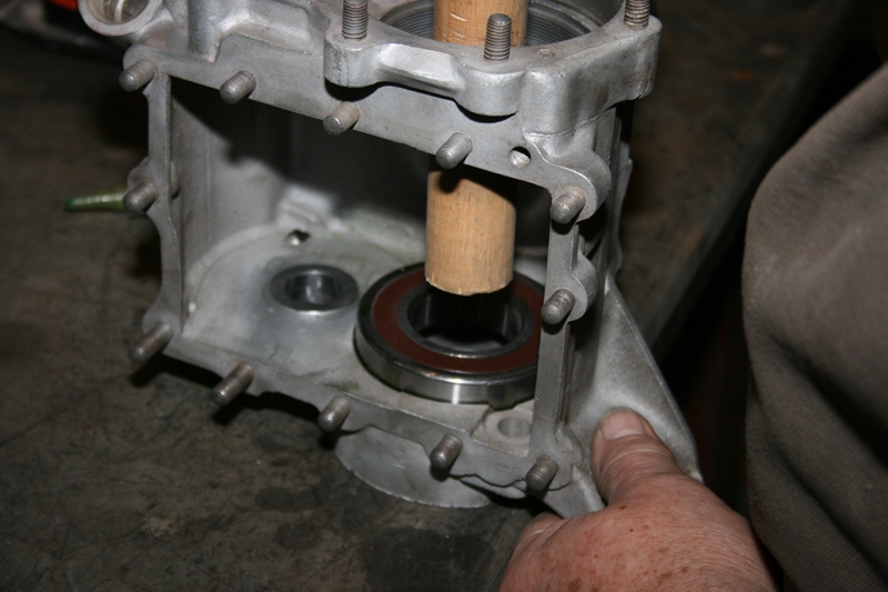
While the paint was left to dry, work began on assembling the internal components of the transmission.  I decided to upgrade the mainshaft bearings to sealed units which are available from Replicant Metals (www.replicantmetals.com).  Using sealed bearings helps to eliminate fluid leaks, which is always a worthwhile improvement.  In order to install the new bearings, the case was carefully heated with a torch to expand the opening while the bearings were placed in the snow to contract.  Once the case was hot, the bearing was quickly dropped in and tapped into place with a wooden dowel.
 
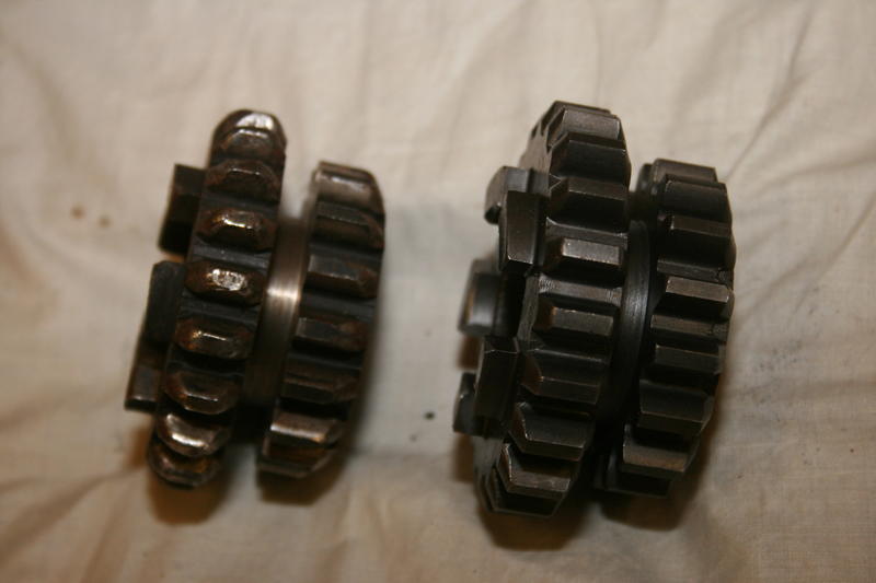
Both my countershaft and mainshaft were well worn, so I replaced them with new units from Eastern Motorcycle Parts (www.easternmotorcycleparts.com).  My slider gear was in terrible shape too and was replaced with a new unit from Eastern as well.  Here’s a side by side photo of my original slider gear and the Eastern replacement.  Definitely is big improvement! 
 
 
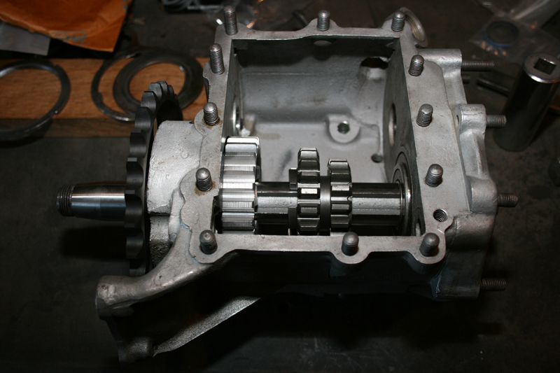
  Assembly was very straight forward, the mainshaft was slid partially into the case, allowing room for the main drive gear and slider gear to be installed, before the mainshaft was slid the rest of the way through the case.
 
 
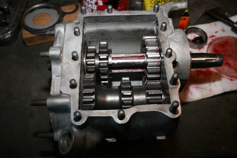
Next new bearings were installed inside the cluster gear and it was held inside the transmission case while the countershaft was pushed through it.  Lots of red grease was used for this step, not only to lube the new bearings, but to hold them in place as some of them rode loose inside the cluster gear.  
 
 
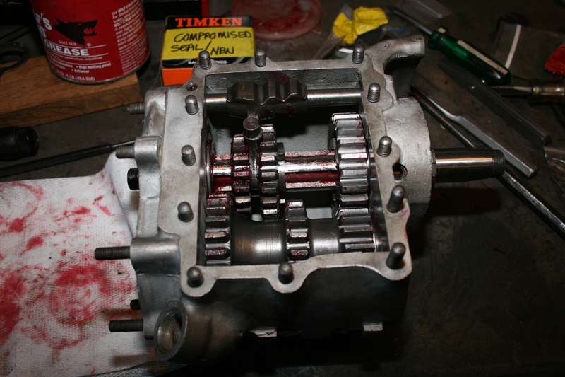
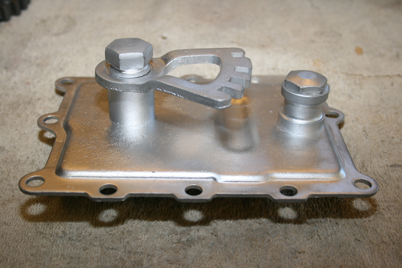
The last thing to install inside the case was the shift fork assembly.  The shift fork attaches to the center of the slider gear and slides back and forth on its own shaft.  An arm in the transmission lid moves the shift fork, which in turn moves the slider gear and engages it with the selected gear on the gear cluster.
 
 
With the internals finished, work began on the kicker assembly.  Using a special lock ring, both the mainshaft and countershaft were secured on the right side of the transmission before the kicker parts were added to the mainshaft. 
 
 
Assembling the parts on the mainshaft was a two man job as there was a spring which had to be compressed while two keys are installed in the end of the mainshaft.
 
 
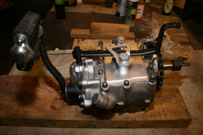
Once everything was stacked onto the mainshaft, a nut and washer was installed to hold the whole assembly in place.  The following photo shows the assembly ready for the kicker cover to be installed.
 
 
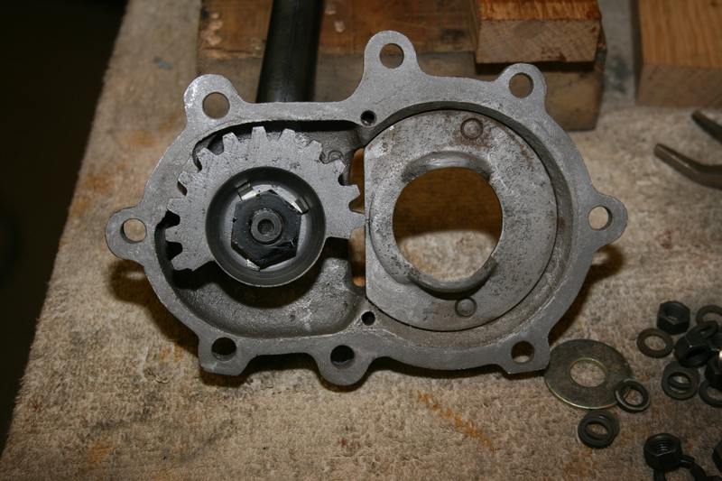
Inside the kicker cover and attached to the end of the kicker arm is a half gear which meshes with the kicker gear that was just installed on the end of the mainshaft.  This half gear turns the mainshaft when you kick down on the kicker pedal.
 
 
A paper gasket and a handful of washers and nuts was all that was needed to complete the kicker installation.  There was a little bit of work left to assemble the transmission lid and it was soon bolted onto the top of case.  
 
 
A couple of new grease fittings finished off the build and we were left with a great looking transmission.
 
 
Editors Note:
If you would like to contribute to the completion of this bike please use the link below.
 
This project started on Black Friday of 2013 with just a set of engine cases and will end with a complete 1933 Harley-Davidson VL making a cross country run in the fall of 2014.  Already a great deal of progress has been made on the restoration of this motorcycle, but more funding is needed to see this project through to the end.
 
Additional articles will continue throughout the remainder of this build and will result in a complete digital archive which takes the reader through the restoration of a 1933 Harley-Davidson, step by step.  By making this information available freely online, future vintage motorcycle enthusiasts will be able to rebuild and maintain these great machines.

We have already gained the support of many of the top compaines in the vintage motorcycle industry.  If you would like to see your company’s logo included not only on the motorcycle, but also on every article, please contact me directly to learn more about our marketing campaign and advertising opportunities. EMAIL

 
Sponsored By


Read More

ACORN NUTS MEET THE MUDFLAP GIRL

ACORN NUTS MEET THE MUDFLAP GIRL–

P/N: MK731: 110-Piece Solid Brass Acorn Nut Assortment Tray 

Brass is class, and a great gift idea for old school bikers! Conveniently stored in the heavy-duty Tray with lid is a 110 piece assortment of Solid Brass Low Crown acorn nuts in 12 of the most popular UNC & UNF nut sizes. 

Available along with a collection of classic inspired parts at www.mrluckys.biz . Or, call “Mr Lucky” direct at 832-559-8560 and get the whole skinny!

The brass acorn nuts add a nice finishing retro touch. Don’t remember if I sent you the press release on the assortment tray or not, so image & copy are attached. The tray as well as the individual bags of 5 & 10 are selling well, and make a good holiday gift.

P/N MK731, $74.99. Made in USA. 

–Mr Lucky
6411 Saffron Hills Dr. Spring, TX. USA 77379

P: 832.559.8560

Here’s the link:
http://www.mrluckys.biz/Shop/c13/p137/110-piece-Solid-Brass-Acorn-Nut-Assortment-Tray/product_info.html

Advertisement

Read More

Mudflap Girl FXR Part 12—She meets S&S

Here’s the link to Mudflap Girl Part 11: http://www.bikernet.com/pages/Mudflap_Girl_FXRs_part_11_The_First_Road_Test.aspx

My son’s Mudflap Girl FXR is running and partially broken in. I even, finally, dialed in the Wire Plus Speedometer, and it’s working. I wish I knew what I was doing wrong, but that puppy works like a champ. I enjoy the tightness of the display and ease of installation. In that small cylindrical Wire Plus display, I get a speedo, a tach, trip gauge, neutral light, turn signal indicators, oil idiot light, and what else?

Okay, so it’s time to turn the Pro Street version of the Mudflap over to my son, Frank, but first we couldn’t leave the bone stock remanufactured 80-inch Evo engine alone. I reached out to S&S for a cam recommendation, and they recently built a relationship with Crane Cams.

Bruce recommended the following stock engine formula: S&S Super E carb, Crane Hi-4 ignition, S&S Cam and S&S easy-adjust pushrods, a Crane dual-fire coil, and the S&S 33-4250 breather and shim kit, for just enough pump to let this motor breathe.

I hauled the Mudflap beast on my Kendon tilt-up combo trailer to Bennett’s Performance, a very clean shop, next to Branch O’Keefe Flowmetrics, on Signal Hill. Eric Bennett, the boss, bought the Bikernet Hearse, immediately fired his girlfriend and started to cruise the backstreets of Long Beach. He traded his bagger for a Sons of Anarchy Dyna, and is about to turn the 88-inch twin cam into a 106-inch S&S night flier. His band, the Signal Hill Billies, transformed their usual light country western twang into dark blues. What the hell did I do? We will bring you reports on his engine transformation. I could swear the all-black lowered hearse smirks at me whenever I roll into his parking lot, but we won’t go there.

I pulled up the other day to find Frank’s Mudflap Girl on a lift center stage. No sooner did I enter the shop when Eric slipped out the back. A mysterious tech sauntered out of the engine room with long gray hair. “Don’t take my picture,” he said, “and don’t mention my name in the article.”

I’ve known him a long time. He’s an experienced Bonneville racer and a multiple-tour Vietnam vet, about my age. He’s only been married once, and is still married to the same woman. “I swear,” he said, “I’ve never pulled my military issue bayonet on my wife.”

I’ve been married five times and Eric three, and he just broke up with his long-time girlfriend. Maybe the graybeard tech with his twisted grin was trying to say something.

What the hell could I say? I set the box of parts on the lift and started to blow the dust off the fresh engine. Eric gave me a new cone gasket, seal, and a Torrington cam bearing, in case the fresh engine was fitted with a poor quality INA bearing—it was. I removed the pipes. The tech removed the plugs, and we jacked up the bike. He popped the pushrod covers and broke out the bolt cutters to remove the stock pushrods without removing the rocker boxes.

“I roll the engine over so the valves are closed when I cut the pushrods,” Graybeard said, “so the valves don’t slam shut when the pushrods snap.”

Then he removed the point cover, and the crane Hi-4 ignition plate. “There needs to be a washer under the fastener holding the Crane point breaker plate,” he barked.

Unfortunately, I had installed the Crane system and breaker plate—my bad. I thought about my fifth wife. He pulled the cone cover with a rare Trock tool, since the master is no longer with us.

With a couple of JIMS magnetic, or H-D lifter tools the lifters were held out of the way while he pulled the stock cam and checked the bearing.

Sure enough, it was an INA cam bearing with about half the rollers of the high quality Torrington cam bearings.

JIMS tools makes a handy cam bearing puller, which was installed, and swiftly, perfectly yanked the stock bearing free. Eric made specific machined aluminum drivers for installing new bearings, which were carefully tapped into place. After it was installed, he reached in to make sure the bearing spun free, with no binding.

Next, he aligned the timing marks on the pinion gear and set up the new S&S breather gear.

Steel breather gears have better dimensional stability than plastic gears. Embedded particles can damage the crankcase breather gear cavity. A screen provides better protection than a slotted gear, so small particles are prevented from entering the gear cavity, where they may damage the gears and oil pump.

The S&S steel gear with welded in screen with larger diameter holes provides improved air flow/oil scavenging from the flywheel cavity. Crankcase flywheel cavity vacuum and oil scavenging are further improved by optimized breather window timing. Breather oil trap scavenging is significantly improved by increased scavenge port duration. These improvements are the result of exhaustive research using digital sampling and data acquisition equipment.

This gear was the standard size for late 1977—‘99 Harley-Davidson big twins. Breather gear kits include breather gear and steel endplay shim kit.

With the new S&S breather gear installed, he started to adjust the endplay with a .120 shim. “That’s usually the one,” he said. As it turned out, we went with .110-inch shim after he checked the fitment with a straight edge. Then he performed a similar operation with the cam to check endplay. We discovered that a .055-inch thick shim was needed in addition to the existing flat shim. He dug around and found one, and we were set to test it with another JIMS special tool.

The S&S 510V bolt-in cam works well with stock or ported heads. The improved ramp design results in low valve train noise. It’s meant for engines up to 96 inches and with compression as high as 10:1. It’s designed to pull its best results in the mid to upper rpm range, 3000 to 5000 rpm.

It was time to set the cam timing with the pinion bearing and breather gear slots. Then the mystery tech cleaned some of the case threads with a tap. “Too much Loctite,” he said. He touched all the stock ¼-20 Allens with blue Loctite and installed the cone and torqued them to 110 inch-pounds. He installed the appropriate washer in my breaker plate, and then the timing plate.

Before he removed the Crane Hi-4 ignition plate, he scribed the plate and the case so the timing would be right where I placed it when everything was put back together—that is, if I didn’t fuck it up in the beginning.

I peeled the S&S quick-adjust pushrods out of their vacuum-packed container and shortened them for ease of placement. These S&S jobs were a breeze. He checked for all the needed pushrod gaskets, and we compared the pushrod lengths to use the short ones on intake valves and the long ones for the exhaust.

“I adjust them the old school way,” he said. “I make sure one intake lifter is at the top of its cycle, and then adjust the other. Then visa-versa.” He waited 20 minutes between adjusting valves for the stock lifters to bleed down, but while he waited, we started to install the pipes. “No time to lose.” He made sure each pushrod would spin after it bled down. In each case, he took the slack out of the pushrod and then turned it out four turns or 24.5 flats. Once he tightened the pushrod lock nuts, he would take the half flat out of the adjustment.

Here’s the Quickee Pushrod Supplement from S&S: To install S&S quickee pushrods, thread the jam nut off the threads towards the ball end and screw the adjuster into the pushrod tube until the threads disengage and the pushrod can be collapsed

When installed and adjusted, S&S Quickee Pushrods must have a minimum thread engagement of .500 or half an inch (Pushrod tube to Adjuster, not including the jam nut) or severe damage to the pushrod as well as your engine may occur.

When adjustment is complete, the jam nut must have full thread engagement with the adjuster screw. If you do not have full engagement, the pushrod is not correct for the application or position.

S&S Quickee Pushrods for S&S Shovelhead and all big twin engines contain two long and two short pushrods. All Sportster model and Harley-Davidson twin Cam 88 pushrodes are the same length.

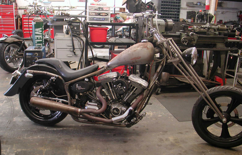
We replaced the pushrod cover clips with another JIMS tool, and I finished installing the Spitfire brake master cylinder and pedal. Once together, we turned on the gas, hit the starter and it fired right to life. Our very experienced Vietnam vet tech let her warm up, adjusted the carb and quietly returned to the engine room to work on a twin cam engine build for a customer. It’s time for my son to pick up his bike and head for a paint shop or the hills.
 

Sources

S&S

Bennett’s Performance

Wire Plus

JIMS

Spitfire

Read More

1964 Pan Head part 4 (frame)

Well, here we are, past the point of no return. In this chapter I cover the reassembly of the 1964FL restoration. I have been working on this classic for the past nine months. I know it says frame above, but the frame was bone stock, no dings, or mods. The customer requested paint over powder, so off it went. We sandblasted it clean, checked for cracks, magna-fluxed the frame for imperfections, and checked all dimensions for tweaks. This puppy was straight. With new neck bearings and cups from J&P the frame flew back together. We cleaned the paint off the engine and transmission mounts and went to work. Assembly was straight forward, almost the reverse of the disassembly. Engine goes in first, followed by the transmission.
 

Primary with belt drive is next. However before the inner primary goes on, make sure you hook up the shift linkage, otherwise there’s not enough room to install the pin and cotter pin. After the linkage and inner primary are on, you can install the main shaft pulley and belt drive clutch. Loosen the transmission and adjust it all the way forward to ease the belt installation. After the belt is on, adjust the transmission rearward to achieve the proper belt tension.
 

I figured this was a good time to install the rear wheel and chain, making sure the proper alignment and chain tension are acquired.

Oil tank and lines were next on my agenda. I opted for a more modern spin on oil filter adapter, it looks nice and makes oil changes a snap. I kept the original oil filter that was polished just in case the owner wants to go all original some day.

The front forks have been completely rebuilt with all new modern seals, I had them polished also, looks nice! My customer decided he wanted a old school look on the wheels like they did in the ’30s and ’40s, so we blacked out the spokes and hubs leaving the star bearing plates and lug bolts the original parkerized coating.

Just about everything that is aluminum was polished like chrome. We kept to the OEM look on the primary and oil tank, which was black with touches of chrome.

The original bugle horn was restored and polished.

As for the clutch shift linkage (mouse trap), it also was completely gone through and restored, polished and looks like new. I did find out why they call it a mouse trap! Got my Fuckin’! finger snapped twice while trying to adjust it, IT HURT BAD!

The brakes have all new shoes, lines and fittings. Front brake is mechanical and rear is hydraulic, all juiced, adjusted and ready to go. Tires we picked are replicas of the day. They are Shinko reproduction white walls. Not the best, not the worst, but fit the budget just right. They have all new tubes, rim belts and have been balanced and trued by me.

The new exhaust went on comfortably with new head clamps. We kept the original muffler. It was salvageable. All the footboards have been rebuilt with new rubber and rivets and foot controls were installed.

The original generator in chapter 3, was a no go, it had a bad armature and wasn’t cost effective for a rewind. So I ordered (cust. request) a new 6v generator with built in voltage regulator, it too looks very nice. Just a quick rundown, the electric system although all 6v, has all new solid state components i.e. electronic dual breaker distributor with a solid state voltage regulator, no mechanical parts.

The electrical has all been installed and wiring is complete less the head light and tail light. Both electrical junction boxes have been rebuilt with new insulators and wiring harness.

There’s a lot of little things like the $5 chrome chain guard I found at the swap meet and some odds and ends I also found in good condition cheap, at the swap meet. You can see them in the photo’s if you look hard. The steering head lock was a nightmare. It took me months to track one down on eBay. Shortly after I purchased the one on eBay, JP Cycles informed me that they finally had one in stock, go figure!

So here she is, just waiting for the tanks to come back from the painter. 
 

ETA on the tins is end of June, then on they go. Hooking up the fuel system and tins installation will be the next chapter, followed by all systems start and run. I plan on giving the bike to Timbo at his semiannual “Ranch Party.”
 
He goes all out with a dozen live bands, free food and drink to all his friends, which is about a thousand or so. People show up weeks ahead to help construct stages, dance floors and the Bar-B-Q area. It is truly a sight to behold, covering five+ acres, your never board, everything from darts to wild monkey sex is going on! But this year is special.
 
Timbo is retiring with 30+ years of service to the Boeing air craft company at Edwards AFB. The bike is his gift to him, so it all has to come together. No pressure for me, HA! If you guys have any questions, feel free to write, or if I left out anything you deem important, ask!

–Tail Gunner out! Checking back with you in July.
 
Sources: 
 
Note: Some 90% of  the parts I used were from J&P Cycles with the exception of a few swap meet finds and the dual electronic ignition from a previous chapter. We found the seat on Ebay. It’s a replica ’48 tractor on pogo. Pipes are classic Paughco replacement units. It looks like a Primo belt drive. The only clue I had was a clutch spacer that was left out for some reason. I contacted Primo, and they said it was an early system and I needed to install the spacer. — Gunner  
 
J&P Cycles
 
Rivera-Primo
 
Paughco
 
Read More
Scroll to Top