Doug Coffey’s RetroMod Panhead Part 1
By Robin Technologies |


Other than the missing sidecar sidecar loops, it has a strong resemblance to a 1957 straight leg rigid frame. Exactly what I wanted.
Bikernet/Cycle Source Sweeps Build, Part 3, Sponsored by Xpress
By Robin Technologies |

Hang onto your asses. This is going to rock your boat, or your solo seat springs. We are building a bike just for you. That’s right. A Cycle Source or Bikernet reader will own this one-off custom at the end of this year. No, I’m not kidding.
This world-class team of builders, lead by Prince Najar, the vast and all-powerful organizer is headed-up by builder/designer Gary Maurer of Kustoms Inc, and Ron Harris of Chop Docs. We have the Texas Bike Works frame, the magnificent Crazy Horse 100-inch engine, and Jules, of Kustoms Inc. hand-made an oil tank. This issue we welcomed another state of the chrome-arts team into the fray, 3Guyz, a manufacturing shop capable of anything. They work out of a former aerospace manufacturing facility in Hillsboro, Oregon. Their mantra is as follows: Providing specialized customizing and performance solutions for American V-Twin and sport motorcycles, Smart cars, and industrial clients.

I spoke to Andy, one of the guys, who introduced me to the boss, Bob, and the other guy, John. Around 2004, they needed a springer, and although they were big fans of Sugar Bear, they decided it was time to manufacturer their own.
“We started by building a dozen all stainless springers,” Andy said. “We still have a few.” Then they discovered the need to build springers for builders who sought flexible units for various finishes. Each springer is custom-made for whatever application any builder needs. In this segment, we will reprint the 3Guyz tech on how to measure a roller for the perfect length springer. They also published a tech on tearing a 3Guyz springer down for finish work.

For more details about fork design and handling, take a few minutes to read through their “Fundamentals of Front Fork Geometry” in the 3Guyz.com tech section.
So here’s what Gary was faced with when the word came from Prince Najar, “3Guyz will make us a springer. Order it, will ya.”

Options:
Brake stay(s): Right, left, none or both (we position them, and provide the correct bolt thread based on the brake system you choose). In this case, we are using Hawg Halters.

Handlebar mounts: Standard is ½-inch through holes on 3-1/2-inch centers in the top tree for solid mounting, designed to use any stock Harley risers. You can add bushing mounts, or larger holes for custom handlebar controls. Or a springer can be ordered without holes for risers. Their springers are available wide or narrow.
Axle diameter: Standard is ¾-inch. You can choose to have us provide a 5/8-inch axle for spool wheels if you prefer.

Fork Stops: Standard is external pin stops in the lower tree based on our bearing cup stop set. You can choose to add in our cup and bearing kit, have us provide the internal stop kit, or specify internal stops by providing the manufacturer details about the stop kit.
Brakes: You can provide the distance from the axle to the brake anchor link point on your brake kit, and we will place the brake anchor where necessary to match it. We can also provide a wide selection of brakes from aftermarket suppliers and pre-fit them to your fork.

Fenders: Left fender mounts, off these springers are available to allow adding the fender of your choice (there are too many possibilities to list here).

How to Measure Your Frame for a Springer Front End Build
To build a springer front end specifically to match your frame, we need a few simple dimensions and facts.
All the directions and examples here are based on the fact that your frame uses a 1-inch neck similar to a big twin H-D. If not, you can use this example, but you will have to give us additional information on the length, inside dimension and outside dimension of your neck to determine, if our system will work with your frame.
To start, set your frame up on a riser (blocks, or a jack) to set it at ride height. That is, where you want it to be when the bike is fully finished, and running down the road. It is best to do this with the rear wheel (in this case Ride Wright wheels) and tire (Metzler) installed to allow you to set the lower frame tubes level with the ground, or slightly raised, as some designs prefer.
Mock-up-frame-height. In this example, we have mounted the rear wheel in the frame, and used a frame jack to set the “attitude” of the frame stance. This step is important, as changes to the angle of the lower tubes to the ground can change the neck height, and neck angle as the frame pitches upward.
We typically use a digital inclinometer to establish the neck angle for our calculations to measure the angle within one tenth of a degree. We do not expect everyone to have one of these. We’ll show you a few other ways to get the neck angle damn accurate with common tools
To measure the neck angle relative to the table, we need to zero the device. In the photo above, you can see that we have used a long straightedge set on top of the table surface to average the table surface. This is important because these lift tables are not flat, and we need to establish a flat average surface plane to measure from.

As you can see, there was an error here. Our floor is sorta flat here as well. Most garage floors at home slope toward the door, and can induce more error. If you are using a lift in your garage, try to set the table across the natural slope of the floor to eliminate that possibility. Most garage floors are somewhat flat side-to-side.

After the gauge is set, simply set the gauge across the top of the neck as shown.

Keep in mind that:
1.The better these measurements are, the more accurately the front end can be built.
2. There are other ways to do this, but this is how we do it.
3. The smaller the neck angle, the less effect small errors have on the length of the fork
Let’s take a look at other ways to measure the angle. A machinist protractor is very inexpensive, and can be used as shown.

Keep in mind here that as we use a level to determine the angle, you must use the same technique on the table to subtract (or add) the correction angle into the measurement for a relative angle.
Another tool to use like this is available at lots of tool stores, and is pretty easy on the wallet. We see it in use in this shot.

Now that we have the neck angle, we need to know how far from the ground the neck bearing is.

Measure from the centerline of the lower neck bearing race (Bearing IN PLACE) directly to the table as shown.

It’s important to measure the lower edge of the bearing in the race, along the centerline of the neck axis.
This one measures 32 and 3/8-inch from the table surface. Try to get within 1/16-inch here.
This allows us to calculate the length of the fork, as long as we know the tire size, type, and brand you will be using. We have a table of “loaded” radius dimensions for most major tire types we can use to determine the distance from the table to the front axle.
With this information, we will build you a springer to fit in the space required, and we will pre-load the springer so that it will settle to this height when it is fully loaded with the bike and average rider weight.
We also use this geometry to select the correct size rocker length and tree selection to provide you with the best steering trail for a safe and smooth ride.
Gary Maurer has been building bikes for years, so I’m sure he has a formula for figuring the springer length or he can follow the instructions here. So, the other crucial variables at this point were the dimensions of the wheels and tires.

I reached out to Ride Wright wheels in Anaheim, California. They manufacture custom wheels, rotors, and pulleys for Harley-Davidson, American Classic, custom chopper and import motorcycles.
“We strive to be your one-stop source for aftermarket custom wheels and tire needs with the hottest styles and various sizes, including super wide or tall rims.”

They make straight, cross, and cross-radial (overlapping) lacing patterns with smooth and diamond cut wire and spoke wheels in 40, 50, Fat 50, 60, 80 and 120 spoke-count styles. They build their own high-polished stainless spokes in diamond cut, twisted, jeweled and blade styles. Finishes include custom colors, powder coating, chrome, and polished hubs and rims.
They also manufacturer steel and aluminum rims. Their soft-lip aluminum rims have no step and are thick enough for engraving or machining.

This is damn exciting, the way this putt is coming together right before our eyes. We now have a complete roller, and soon the sheet metal fabrication will begin under the guidance of Gary, Jules, and Ron. Hang on for the next chapter. And remember you can win this one-off custom chop. Just subscribe to Cycle Source or Bandit’s Cantina on Bikernet.com. Or just fill out the application and keep your money. No purchase is required, but don’t tell the other guy.
–Bandit

Xpress
http://mysmartcup.com/
Crazy Horse
http://www.crazyhorsemotorcycles.com/

Texas Bike Works
www.TexasBikeWorks.com

Kustoms Inc.

Chop Docs


Accel
Accel-ignition.com

Fab Kevin
.jpg)
D&D Exhaust
http://www.danddexhaust.com/
Wire Plus
http://www.wire-plus.com/
Barnett
Barnettclutches.com

Rocking K Custom Leathers
Ride Wright Wheels


Bell

Metzeler Tires




Mudflap Girl FXRs, Part 10, Suspension Tuning and Le Pera Seat
By Robin Technologies |
Mudflap 8: http://www.bikernet.com/pages/Mudflap_Girl_FXRs_Part_8_Wiring_World.aspx
Mudflap 9: http://www.bikernet.com/pages/Mudflap_Girl_FXRs_Build_part_9.aspx

I’ve been riding and tuning Mudflap Girl FXR for a couple of months. We finally dialed in our rear shocks, maybe. David Zelma, from Progressive taught me the ropes regarding spring pressure and travel. We will get into that. We have also been monkeying with my Spitfire Girder shocks. Again, the problem is travel.
My son’s FXR faces similar dilemmas, but hopefully we will be able to transfer knowledge from my bike to his. Fortunately, Progressive suspension is just down the street in Orange County, so David Zelma stopped by with a variety of springs. “Your shock angle is more like a Dyna Glide than an FXR,” David said, “which makes for much more severe spring rates.”

I kept trying tougher and tougher FXR or touring H-D springs and the rate of sag was too much, indicating a too-soft spring. Also, I had to mess with additional bumpers, limiting the shock travel to prevent the fender from smacking the Avon tyre. It’s a humorous dilemma, one that any sport bike rider would scoff at, since he doesn’t care if there’s a foot of air between the rear tire and the fender.
Ultimately, we ended up with 12.5-inch Progressive Dyna shocks, but my travel, with limiters, is just over ¾ of an inch, sort of the same as a lowered Softail.
“I’m not happy with this system,” David said. “I want to see more travel for a comfortable ride.”

I like the way the bike looks, and I will ride it to Mammoth Lake next weekend to hook up with the Hamsters on their long road to Sturgis from the West Coast. That’s the iron test.
Next, I looked at the front Spitfire Girder shocks and discussed it with Rick Krost, who messes with bicycle seat shocks for custom applications. He removes the stock springs and switches them for cut springer springs. They were, unfortunately, too soft for the girders. Our problems with the seat shocks were two fold. The springs were 300-pound jobs and the shocks did very little to dampen the ride. So I went on a hunt. I discovered RockShox and Fox bicycle shocks, which run over $500 a piece. Good god!

Rick supplied me with a couple of RockShox with springs rated at 500 pounds per inch. Again that’s too tough, so I tried running one shock in a position more directly in line with the girder, another Rick suggestion. With one 300-pound rated spring I received good movement, but again very limited, like just over a ½ inch of travel. I’m still on the hunt for 2 inches of travel, and fortunately the Spitfire girder affords me the ability to mess with the positioning of a shock. I found a Fox shock that could be perfect, but the cost was prohibitive. RockShox also allows me a variety of spring rates, but of course I can’t find a price on their web site.

While on the girder shock hunt, we worked with Le Pera on a seat for my son’s Mudflap Girl FXR. Christine and Bob Le Pera took over their dad’s company when he passed. Christine picked my brain for styling, and then sent me a seat pan.

First, I made a bracket to catch the supplied tongue, welded under the seat. Before final welding, I may move the frame bracket back a ½-inch. Even with the tongue extended, I’m still not perfectly happy.

With the pan in place, we marked mods and adjustments with a felt pen and started hours of grinding and fitment. Then Ray C. Wheeler hacked-out an extension to afford my son enough seat for a passenger.

We cut a chunk of like thickness sheet metal and made a cardboard template, which was transferred to the sheet of tin and cut out with cut-off wheels. We could have made smooth work of it with a plasma cutter, but the grinding would burn the clock, and warping might become an issue.

We spent hours grinding, hammering and fitting until we thought we were close. I would love to find an English wheel and make the time to take a sheet metal class. Then we tacked the pan to our extension, and worked on it some more. I didn’t want to send it back to Le Pera’s historical shop looking like shit, so we worked over the pan extensively, and then drilled additional rivet holes to match the traditional pattern of Le Pera holes.

Le Pera is the home of the chopper seat, the cool, low, stylish, bare bones butt pads. “We can’t make ‘em fast enough,” Christine said. They have also shifted to more dresser seats, and seats for tall guys are popular.

This is their 40th anniversary in the seat-making business, and their focus for this year is new products, not parties. They constantly study new fabrics, threads, and embossed products. While in Italy at a dealer show, a customer approached Christine and told her, “Le Pera is the Ferrari of custom seats.”

When I spoke to Christine, my first question was regarding my seat pan. “How did we do?”
“You did a good job,” Christine said. “According to Bob, it was easy to cover.”
After they inspected our Bikernet shop handy work, she sent the pan out for powder coating. Then they installed a tough rubber edging molded over a metal insert. The metal grabs the pan securely, and the rubber clings securely to the metal. Together they protect the cover fabric.
While the pan is prepped for padding, the Le Pera liquid foam formula spilled into the standard Silhouette foam mold and was clamped into place while it cured.
Bob Le Pera, Christine’s brother, glued the foam figure of the seat to the pan and started hand-shaving the foam. “He’s the artist,” Christine said. Once shaped, the seat was ready for the fabric cover.
Bob chose a long-lasting comfortable fabric, but the master of seat patterns, Gus, a 32-year member of the team, laid out and customized the seat template, extending the standard Silhouette pattern, which he transferred to the resilient fabric, cut out the various pattern segments, and sewed the pieces together with upholstery-grade, ultraviolet-light-resistant bonded polyester thread. The color selection is vast.
Another long-term veteran member of the Le Pera team, Rick, with 27 years under his leather belt, completed the seat. He attached the stitched cover over the hand-shaped foam, made sure all the lines were symmetrical and tacked it in place with a couple of rivets, starting at the rear with a rivet gun.
With the completed seat in hand, Rick carefully glued a protective template of carpeting on the bottom.
I asked Christine about ordering custom seats from them, and they are open to a variety or requests. It’s often best to work with a knowledgeable dealer who can give you tips and knows how to speak the lingo to the Le Pera staff. You can always e-mail the staff and hit them up for info. Try to nail down a style before you reach out. Styles range from thin, low, and sleek, to touring, or tall guy seats. Check their catalog for ideas, and once you’ve nailed the basics down, you can discuss custom stitching, inlays, fabrics, leathers, and or embossing, and of course an affordable budget.

With the seat in hand and the Spitfire forward controls mounted and dialed it, Frank’s Mudflap Girl FXR is ready for a ride. He just needs a plate, registration, and insurance documents, and we will begin the Eddie Trotta break-in routine.
Le Pera Seats
D&D Exhaust
Biker’s Choice
JIMS Machine

MetalSport
BDL/GMA
Wire Plus
Branch O’Keefe
Bennett’s Performance
Custom Cycle Engineering
Saddlemen
Bub
Progressive Suspension
Check out my road test in the next chapter: http://www.bikernet.com/pages/Mudflap_Girl_FXRs_part_11_The_First_Road_Test.aspx
Rivera-Primo Brute II Install
By Robin Technologies |

We have a goofy Shovelhead in the Bikernet shop called the 1928 Shovelhead. It has 21-inch wheels front and rear in a Paughco rigid frame, but some 1928 elements were used, including the re-pop semi-flat sided tanks, the rear fender and perhaps the seat. The bike was conceived by Bandit the bastard, built by the crew at Rick Fairless’ Strokers Dallas, with the help of Randy Simpson who manufactured the handlebars.

The bike has contained a couple of hiccups and hasn’t been ridden much. Recently, one of Bandit’s friends needed a ride, so Bandit shipped this puppy to Washington. Richard Kransler installed new Avon tires and took it out for a spin. Unfortunately, the early Rivera-Primo belt, stuffed into the semi-stock inner primary, snapped and the 1984 Shovelhead was garaged. More recently, Richard concocted a deal with Bandit for a van in exchange for his Sturgis Shovel, and returned the 1928 Shovelhead to the headquarters, where the gang went to work on it.

With Richard’s info, and after consulting with Ben Kudon at Rivera-Primo, a plan was put into motion to make this wild puppy more rideable. We needed to add an oil filter, rerun the oil lines to reduce heat, fix the sumping problem, replace the primary drive, and then we discovered a loose valve seat, but we’ll get to that.


This is also a two-part tech. We first installed the Brute II Extreme Belt drive with a 1 ½-inch wide 11mm belt with electric start in the closed primary. Then we will install the most magnificent Rivera-Primo Pro Clutch. Since this is a jockey shift, it will be interesting to test both the stock clutch against a new clutch system that’s state of the art. We will forward all of our extensive reports directly to the boss and all Bikernet readers.

We discovered immediately that the front Brute II pulley was larger than the previous model, which was disappointing because it called for more clearance in the case, which weakened one of the primary fastener locations. Not a big deal, so we went to work with a pneumatic cut-off blade and emery wheels.

It’s critical to disconnect the battery, especially while working on the inside of any Shovelhead primary. It’s too easy to bump or pull on the starter solenoid, and you could lose a finger pronto. Fortunately, we have a selection of JIMS tools and pullers for this operation.

Here’s the fine print from Rivera-Primo: Primo Belt Drives are designed and engineered to correctly fit stock Harley-Davidson motorcycles. Aftermarket frames, primary covers, engine shafts, or clutch hubs may cause installation problems. Also bent frames, sagging motor mounts, worn transmission mounts, and other defects may cause shortened belt life due to incorrect pulley alignment.

If you have a stock system being replaced, here’s the dope: Remove the front pulley, chain, compensator and chain adjuster. Remove oil lines to primary and plug or clamp to prevent leakage. Cut the chain oiler hose 3 inches from the oil pump and permanently plug it. All belts must be run completely dry, without lubrication of any kind. Therefore, remove all oil from inside the primary covers.

The spacer behind the front pulley should be removed before installing the belt drive. This spacer may or may not be required to correctly align the pulleys. If a spacer is needed for alignment, various sizes are available from your local Primo-Rivera dealer (part number PX-1, is a package of various sizes).

We discovered a very tight belt. We had to carefully install the belt in the case first. Then the front pulley was installed onto the main shaft, but just slightly to afford us some flexibility with the clutch hub. We re-greased the bearing on the clutch hub and inside the clutch shell. With the handle of a plastic hammer, while prying it with a large screwdriver, we were able to drive the clutch shell over the hub with some gentle persuasion.

We tracked the belt, and installed the same spacer from the last system behind the engine pulley. With the bike jacked and the plugs pulled, we turned the engine over to test the running direction. We made sure to run the engine over in a forward direction. It’s not a bad idea to use a straight edge at first to make sure the pulleys have the proper spacing.


“Spacing the motor pulley outward will cause the belt to track towards the outer primary cover,” said Ben. “If spaced too far out, the belt will rub on the inside of the clutch shell.

Then we attempted to install the outer, aftermarket tin cover and discovered a significant problem. It rubbed against the clutch shell. So far, our inner primary clearance adjustments worked.

We were concerned about the tightness of the belt. It seemed severe to us, and to Bandit. According to the Brute II directions, the belt requires a minimum of ½-inch up and down play at the center of the belt, and up to ¾-inch. We barely encountered ¼-inch of tough play. “Free play is critical,” Ben said, but when Bandit questioned him, he muttered something about ¼-inch being okay, since the belt was so stiff.

The crew even considered replacing the system with a stock chain, to avoid issues. We took the system apart and studied each element, and investigated. I looked into a longer belt, or installing the earlier unit again, which had its benefits with the smaller engine pulley and tapered clutch shell that fit in the primary. We installed the belt again and tested the flex—still tight. We cut a hole in the tin primary, eliminated that problem and affording us tremendous venting. We live and breathe by the Optimist Creed, sort of code of the west. We are hoping once the belt settles in and warms, we will encounter additional flex and no stress on the engine and trans bearings.

“This is a much stronger, more technically advanced belt over the previous 14mm belt,” Ben assured me. We will give it a shot. Venting is a critical element. Primo recommends venting enclosed belt installations to allow cool air to circulate into and out of the primary case. This will keep heat expansion to a minimum and extend belt life.


Special Note: Big Twins from 1969 require a #16657 motor seal. Next we will install the new Pro-Clutch from Rivera Primo and test it, so we will be in and out of this primary case and reporting back on our findings.


In the meantime, we rerouted the oil lines, added an oil filter mount, and an oil pressure gauge for more capacity, cooling, and cleaner oil. We worked on the sumping problem, and then discovered that a valve seat was loose in the rear head. We pulled the heads and delivered them to Branch O’Keefe for repairs.

Our shop intern and overall handy-man, Kyle Olsen, our official Bikernet electrician, will test this bike. We are determined to make it a solid rider, and Kyle will bring us reports and handling complaints in the near future.


We modified the jockey shift and added the 5-Ball for easy shifting that’s out of the way of our thighs at stops.

And Bandit has a code, a good one. All bikes need rear chain guards, and this bike doesn’t have one. We will remedy that. Plus we have a brand new set of Nology plugs and plug wires to install. Hang on for the next report.

1964 Pan Head part 4 (frame)
By Robin Technologies |


Oil tank and lines were next on my agenda. I opted for a more modern spin on oil filter adapter, it looks nice and makes oil changes a snap. I kept the original oil filter that was polished just in case the owner wants to go all original some day.

The front forks have been completely rebuilt with all new modern seals, I had them polished also, looks nice! My customer decided he wanted a old school look on the wheels like they did in the ’30s and ’40s, so we blacked out the spokes and hubs leaving the star bearing plates and lug bolts the original parkerized coating.


Just about everything that is aluminum was polished like chrome. We kept to the OEM look on the primary and oil tank, which was black with touches of chrome. 

As for the clutch shift linkage (mouse trap), it also was completely gone through and restored, polished and looks like new. I did find out why they call it a mouse trap! Got my Fuckin’! finger snapped twice while trying to adjust it, IT HURT BAD!

The brakes have all new shoes, lines and fittings. Front brake is mechanical and rear is hydraulic, all juiced, adjusted and ready to go. Tires we picked are replicas of the day. They are Shinko reproduction white walls. Not the best, not the worst, but fit the budget just right. They have all new tubes, rim belts and have been balanced and trued by me.

The new exhaust went on comfortably with new head clamps. We kept the original muffler. It was salvageable. All the footboards have been rebuilt with new rubber and rivets and foot controls were installed. 
The original generator in chapter 3, was a no go, it had a bad armature and wasn’t cost effective for a rewind. So I ordered (cust. request) a new 6v generator with built in voltage regulator, it too looks very nice. Just a quick rundown, the electric system although all 6v, has all new solid state components i.e. electronic dual breaker distributor with a solid state voltage regulator, no mechanical parts. 

The electrical has all been installed and wiring is complete less the head light and tail light. Both electrical junction boxes have been rebuilt with new insulators and wiring harness.

There’s a lot of little things like the $5 chrome chain guard I found at the swap meet and some odds and ends I also found in good condition cheap, at the swap meet. You can see them in the photo’s if you look hard. The steering head lock was a nightmare. It took me months to track one down on eBay. Shortly after I purchased the one on eBay, JP Cycles informed me that they finally had one in stock, go figure!


Mudflap Girl FXR Part 12—She meets S&S
By Robin Technologies |
Here’s the link to Mudflap Girl Part 11: http://www.bikernet.com/pages/Mudflap_Girl_FXRs_part_11_The_First_Road_Test.aspx

My son’s Mudflap Girl FXR is running and partially broken in. I even, finally, dialed in the Wire Plus Speedometer, and it’s working. I wish I knew what I was doing wrong, but that puppy works like a champ. I enjoy the tightness of the display and ease of installation. In that small cylindrical Wire Plus display, I get a speedo, a tach, trip gauge, neutral light, turn signal indicators, oil idiot light, and what else?

Okay, so it’s time to turn the Pro Street version of the Mudflap over to my son, Frank, but first we couldn’t leave the bone stock remanufactured 80-inch Evo engine alone. I reached out to S&S for a cam recommendation, and they recently built a relationship with Crane Cams.

Bruce recommended the following stock engine formula: S&S Super E carb, Crane Hi-4 ignition, S&S Cam and S&S easy-adjust pushrods, a Crane dual-fire coil, and the S&S 33-4250 breather and shim kit, for just enough pump to let this motor breathe.

I hauled the Mudflap beast on my Kendon tilt-up combo trailer to Bennett’s Performance, a very clean shop, next to Branch O’Keefe Flowmetrics, on Signal Hill. Eric Bennett, the boss, bought the Bikernet Hearse, immediately fired his girlfriend and started to cruise the backstreets of Long Beach. He traded his bagger for a Sons of Anarchy Dyna, and is about to turn the 88-inch twin cam into a 106-inch S&S night flier. His band, the Signal Hill Billies, transformed their usual light country western twang into dark blues. What the hell did I do? We will bring you reports on his engine transformation. I could swear the all-black lowered hearse smirks at me whenever I roll into his parking lot, but we won’t go there.

I pulled up the other day to find Frank’s Mudflap Girl on a lift center stage. No sooner did I enter the shop when Eric slipped out the back. A mysterious tech sauntered out of the engine room with long gray hair. “Don’t take my picture,” he said, “and don’t mention my name in the article.”

I’ve known him a long time. He’s an experienced Bonneville racer and a multiple-tour Vietnam vet, about my age. He’s only been married once, and is still married to the same woman. “I swear,” he said, “I’ve never pulled my military issue bayonet on my wife.”
I’ve been married five times and Eric three, and he just broke up with his long-time girlfriend. Maybe the graybeard tech with his twisted grin was trying to say something.

What the hell could I say? I set the box of parts on the lift and started to blow the dust off the fresh engine. Eric gave me a new cone gasket, seal, and a Torrington cam bearing, in case the fresh engine was fitted with a poor quality INA bearing—it was. I removed the pipes. The tech removed the plugs, and we jacked up the bike. He popped the pushrod covers and broke out the bolt cutters to remove the stock pushrods without removing the rocker boxes.

“I roll the engine over so the valves are closed when I cut the pushrods,” Graybeard said, “so the valves don’t slam shut when the pushrods snap.”

Then he removed the point cover, and the crane Hi-4 ignition plate. “There needs to be a washer under the fastener holding the Crane point breaker plate,” he barked.


Unfortunately, I had installed the Crane system and breaker plate—my bad. I thought about my fifth wife. He pulled the cone cover with a rare Trock tool, since the master is no longer with us.


With a couple of JIMS magnetic, or H-D lifter tools the lifters were held out of the way while he pulled the stock cam and checked the bearing.


Sure enough, it was an INA cam bearing with about half the rollers of the high quality Torrington cam bearings.


JIMS tools makes a handy cam bearing puller, which was installed, and swiftly, perfectly yanked the stock bearing free. Eric made specific machined aluminum drivers for installing new bearings, which were carefully tapped into place. After it was installed, he reached in to make sure the bearing spun free, with no binding.


Next, he aligned the timing marks on the pinion gear and set up the new S&S breather gear.


Steel breather gears have better dimensional stability than plastic gears. Embedded particles can damage the crankcase breather gear cavity. A screen provides better protection than a slotted gear, so small particles are prevented from entering the gear cavity, where they may damage the gears and oil pump.

The S&S steel gear with welded in screen with larger diameter holes provides improved air flow/oil scavenging from the flywheel cavity. Crankcase flywheel cavity vacuum and oil scavenging are further improved by optimized breather window timing. Breather oil trap scavenging is significantly improved by increased scavenge port duration. These improvements are the result of exhaustive research using digital sampling and data acquisition equipment.
This gear was the standard size for late 1977—‘99 Harley-Davidson big twins. Breather gear kits include breather gear and steel endplay shim kit.

With the new S&S breather gear installed, he started to adjust the endplay with a .120 shim. “That’s usually the one,” he said. As it turned out, we went with .110-inch shim after he checked the fitment with a straight edge. Then he performed a similar operation with the cam to check endplay. We discovered that a .055-inch thick shim was needed in addition to the existing flat shim. He dug around and found one, and we were set to test it with another JIMS special tool.

The S&S 510V bolt-in cam works well with stock or ported heads. The improved ramp design results in low valve train noise. It’s meant for engines up to 96 inches and with compression as high as 10:1. It’s designed to pull its best results in the mid to upper rpm range, 3000 to 5000 rpm.

It was time to set the cam timing with the pinion bearing and breather gear slots. Then the mystery tech cleaned some of the case threads with a tap. “Too much Loctite,” he said. He touched all the stock ¼-20 Allens with blue Loctite and installed the cone and torqued them to 110 inch-pounds. He installed the appropriate washer in my breaker plate, and then the timing plate.


Before he removed the Crane Hi-4 ignition plate, he scribed the plate and the case so the timing would be right where I placed it when everything was put back together—that is, if I didn’t fuck it up in the beginning.

I peeled the S&S quick-adjust pushrods out of their vacuum-packed container and shortened them for ease of placement. These S&S jobs were a breeze. He checked for all the needed pushrod gaskets, and we compared the pushrod lengths to use the short ones on intake valves and the long ones for the exhaust.

“I adjust them the old school way,” he said. “I make sure one intake lifter is at the top of its cycle, and then adjust the other. Then visa-versa.” He waited 20 minutes between adjusting valves for the stock lifters to bleed down, but while he waited, we started to install the pipes. “No time to lose.” He made sure each pushrod would spin after it bled down. In each case, he took the slack out of the pushrod and then turned it out four turns or 24.5 flats. Once he tightened the pushrod lock nuts, he would take the half flat out of the adjustment.

Here’s the Quickee Pushrod Supplement from S&S: To install S&S quickee pushrods, thread the jam nut off the threads towards the ball end and screw the adjuster into the pushrod tube until the threads disengage and the pushrod can be collapsed
When installed and adjusted, S&S Quickee Pushrods must have a minimum thread engagement of .500 or half an inch (Pushrod tube to Adjuster, not including the jam nut) or severe damage to the pushrod as well as your engine may occur.
When adjustment is complete, the jam nut must have full thread engagement with the adjuster screw. If you do not have full engagement, the pushrod is not correct for the application or position.
S&S Quickee Pushrods for S&S Shovelhead and all big twin engines contain two long and two short pushrods. All Sportster model and Harley-Davidson twin Cam 88 pushrodes are the same length.
We replaced the pushrod cover clips with another JIMS tool, and I finished installing the Spitfire brake master cylinder and pedal. Once together, we turned on the gas, hit the starter and it fired right to life. Our very experienced Vietnam vet tech let her warm up, adjusted the carb and quietly returned to the engine room to work on a twin cam engine build for a customer. It’s time for my son to pick up his bike and head for a paint shop or the hills.
S&S
Bennett’s Performance
Wire Plus
JIMS
Spitfire
Bikernet/Cycle Source Sweeps Build Part 7 Sponsored by Xpress
By Robin Technologies |
Hang on. We are two weeks away from running out to Vegas for Bikefest and pulling the winner of this most magnificent custom motorcycle, specifically built for Bikernet and Cycle Source fans, readers, and subscribers. You need to sign up, if you haven’t, or come to the Cashman Center in Vegas to grab a card and sign up for the drawing. You don’t need to be on site to win. After Bikefest, the scooter will return to Kustoms Inc. near Detroit, for final tuning and break-in before being shipped to the winner.

So here’s the update in a flash, after Bonneville, and heading smack dab against a Cycle Source Deadline. “I’m way behind,” said Chris Callen, the esteemed Editor da Emperor, in Chief, in Charge, in Trouble. This year has turned into the scrambling year. We are scrambling to finish projects; builders are scrambling to finish bikes. Chris scrambles every month to finish a magazine. It’s bananas.
The bike was displayed in Sturgis at the Broken Spoke. Then it returned to Grand Ledge, Michigan, down the street from Ron Finch, for final manufacturing and paint by the master of Chop Docs, Ron Harris, but let’s finish the pieces first.
“I kill batteries no matter what I do,” Gary Maurer said as we started to discuss the battery box. “When I carefully rubber-mount the bastards, they vibrated enough to rip the battery cables to shreds.” So now he puts a small rubber lining under the battery and bolts the unit down hard with Jules-made steel battery straps. He is now using Brail and Ballistic batteries with some luck. This is where I started to learn more manufacturing processes from Gary and Jules, again.
It’s interesting. I don’t consider myself a builder, and when I work with someone with the manufacturing knowledge of the Kustoms Inc. team, I know I’m just an enthusiast, not anywhere near a pro builder. This story contains a couple of fine examples of their expertise. The battery straps are easily bent after marking the position for the bend on the top corner edge of the battery. Jules made the hand bend with a solid bar of steel, and then noted the amount of metal used in the radius and worked it into the formula for the next bend so the strap fit the battery perfectly.
“There is a mathematical formula for this process,” Gary said. “You need to add or subtract material from the next bend, but we bend one side and then adjust the other.”
I also noted how perfectly the fender edge fit the line of the tire, since most fenders do not align with the tire radius. “We often scribe the radius of the tire on the fender and cut it to match perfectly,” Gary said.
He uses thick welder ground cable stock taped to the fender to give him the proper fender clearance. “Sometimes we use chunks of busted rear drive belts,” Gary said. “Sometimes, if need be, we can double the belt, or mesh the teeth for a slightly larger space.”
They break the chain to be as close to the center of the adjustment path as possible, with the engine, primary and transmission in place. Then they adjust the chain to be bowstring tight, and then they tape the spacing material to the tire and start mounting the fender.
This Bare Knuckles fender was bobbed and channeled on both sides by Jules. She often cuts with a plasma cutter, and then works the edge with Matabo grinder with flap wheels. Bare Knuckle fenders are made with solid, thick spun steel. They are as strong as a battleship hull and easy to work with. “Our plasma was toast,” Gary said, “so she used a high-speed cut-off wheel, then the Matabo and flap wheels.
I like the exhaust system he built with D&D components and a carbon fiber muffler. I asked how he held the components accurately together for tacking. “I start generally, but not always, with the muffler in place and move forward,” Gary said. “I hold the chunks in place with three fingers and tack them.” If his weld pulls away from the joint, he adds a small ball of rod to one piece, then holds them together, and heats the ball until it flows to the other tubing piece.
Note how Jules fashioned the lower fender mount to the frame so it acted as a battery strap mount and fender mount.
Then Gary built the sissy bar by hand-bending the steel rod. He machined each chunk of bar stock for the frame rails, and drilled them ½-inch so the rail would simply insert into the welded boss. Then he drilled and tapped them for setscrews. On the top, he welded a machined bung to the bar, and a drilled and tapped the bung to the fender, so the fastener simply slips through the sissy bar tab and screws into the solid bung on the fender.
With all the components tested and brushed with flapper wheels, Ron Finch stopped by and picked up the components for the trip to Ron Harris, a third generation paint and body shop guy. “I couldn’t touch a paint gun until I could bump a fender,” Ron said of his granddad. Back in the day, bodywork was hammered and filled with brazing and lead.
“My dad called Bondo Chinese lead,” Ron said. Then he ran down the Chop Docs custom paint process. From the photos, paintwork slides along like ironing an old pair of Levis (who the hell does that anymore?), but any top-notch painter has the talents of a concert violinist. It may look easy, but there’s a refined eye and level of perfection that turns any steel surface into a perfectly smooth piece of art.
As soon as Ron Finch dropped off the components and peeled out, Ron Harris cleaned the welds with a cookie wheel, and then scuffed all the surfaces with 80-grit for a world-class bonded protective coating. Initially, paint was used solely to protect a surface. Now it protects and adds the final illustrious finish.
Then he coated all the sheet metal surfaces with a filler Bondo skin coat and block-sanded the surfaces. This is where perfection and talent come into play. I’ve been there. I couldn’t Bondo a baby moon hubcap and make it look like new. There’s an eye for sanding just the right level of Bondo to capture the perfect slick surface.
He followed the Bondo coating with a skim coat of putty to capture imperfections, and then tested his eyes with various levels of Emory paper from 80-grit, to 150, to 320, so he can minimize his primer usage.
“I’ve been working with Stage 5 Coatings for two years,” Ron said.
Stage 5 Coatings was established in 2008 and is the newest and one of the fastest growing coatings suppliers in the United States. We are committed to selling jobber direct and establishing an exclusive territory for anyone that carries our lines. We strive to offer the best values available in the market. We are a small company that is personal and ethical. We build a personal working relationship with every customer, whether they are our largest or smallest. We believe when a customer buys from us, a partnership is formed, and is not just another customer. We have the industry experience to put ourselves in your shoes and understand the everyday struggles in the body shop business. From us to the jobber to manufacturing, we have the personal hands-on experience in all areas of the aftermarket coatings industry.
States with Stage 5 or Technico:
Michigan New York
Illinois Missouri
Texas Oklahoma
Wisconsin Oregon
California Arizona
Washington Georgia
Maryland Caribbean
Virginia
Ron is working with Ken Dudley on a line of Chop Docs candies. After he primed all the surfaces, he used a black spray bomb dusting to cause imperfections to surface. After any pits or surface maladies were dealt with, he water-sanded everything with 400 grit wet and dry, and then hand-sanded with 600 grit and finished off with Scotchbrite.
With the components hung in a booth, he primed them with two coats of sealer, and then hit them with the silver base coat and inner clear before taping off for the black pearl inlay. Then everything was cleared again and sanded with 600-grit.
This was Ron’s first attempt with green variegated leaf* using Mona Lisa glue to attach it to the paint surface. “It’s like a very thin, watered-down Elmer’s glue,” Ron said. “The leaf is so thin, it’s like dust in your hands.”
Once the leaf was glued into place and the area cleaned with a cotton ball or a brush, Ron hit it with another coat of inner clear, which locks the base down and leaves sort of a satin surface to adhere any art to, such as pin striping by John Harrow, who used a one-shot enamel sign paint called Kansas City Teal.
Now for the final six layers of gloss clear coats and 1500 grit wet sanding, followed by 3000 grit with water, and then buffing with polishing compound, finishing glaze, and spit shine. It’s Saturday, and by Monday, all the elements will be returned to Gary and Jules and Kustoms Inc. for final assembly. Ron volunteered to help. Unfortunately, he’s 140 miles away, but he drove out and spent all day, Sunday, helping with assembly. “It’s 80 percent there,” Ron said on his way home.
Speaking of volunteer efforts, this has been an amazing build with efforts from a variety of sources, all to create a bike we are giving away. No one made a dime off this puppy. It’s all American-made, and the whole gang pulled together to offer Bikernet and Cycle Source readers a shot at a world-class custom motorcycle—thanks. Chance of a lifetime, goddammit.
Dimensions: 5½” x 5½”


Xpress
http://mysmartcup.com/
Crazy Horse
http://www.crazyhorsemotorcycles.com/

Texas Bike Works
www.TexasBikeWorks.com

Kustoms Inc.
KustomsInc@hotmail.com

Chop Docs
www.Chopdocschoppers.com

3 Guyz
www.3Guyz.com

Accel
Accel-ignition.com

Fab Kevin
http://www.fabkevin.com/home.htm
.jpg)
Evil Engineering
www.evil-engineering.com
D&D Exhaust
http://www.danddexhaust.com/
Wire Plus
http://www.wire-plus.com/

Barnett
Barnettclutches.com

Rocking K Custom Leathers
howard.knight@montana.com
Rivera Primo
www.RiveraPrimoInc.com

Spectro Oils
www.Spectro-oils.com

Bell
www.moto@rcn.com

Metzeler Tires
www.metzelermoto.com
.jpg)
Hawg Halters

Handy Industries
www.HandyIndustries.com

Grip Ace
www.gripace.com
Biker’s Choice
www.bikerschoice.com
Aeromach
www.aeromachmfg.com

Ride Wright Wheels
www.ridewrightwheels.com

Biker Pros
www.BikerPros.com

Bare Knuckle Choppers
www.bareknucklechoppers.com

Saddleman Improves the Amazing Shrunken FXR
By Robin Technologies |

SADDLEMEN MODS TO THE SHRUNKEN FXR–In a world where over promising and under delivering has become all too common here is a gem I must share. The Bikernet built Shrunken FXR has become my daily rider and needed a couple small adjustments to be just perfect for me.
One detail was the too small seat or the bike was too fast (pick one). So I rode my bike over to meet the nice folks at Saddlemen and see what they could do to help me out with my seat. Upon arriving at the Saddlemen facility I spent time with guys from the front office to the guys in the shop ( all of whom took great interest in my motorcycle and the seat they were going to design and build). I noticed from the get-go these people were all riders. I shouldn’t be impressed by that, but there are so many folks in this industry who don’t even ride anymore.
We discussed what I needed (lumbar support) and a lip on the edge of the seat to keep me from being bucked off or sliding onto the rear fender. We also discussed the lines of the bike and that in the case of the Shrunken FXR , less was more. After the team and I spent a great deal of time figuring out what we wanted and didn’t want I was able to walk around the shop and see the whole seat making process from start to finish. man was I impressed!
So many talented folks all working together to put out an amazing array of products designed by and for riders! It was a real treat to see this and made me truly appreciate what they do much more. Great companies, in my opinion, are made of the people who work for them. So I left my bike for mock-up, and received a call back in a week.

When I showed up I saw the foam of the seat had been formed and pan had been constructed. We discussed coverings and stitching, again less is more. They got it and even pointed out to me the lines of the bike would be reflected in the seat.

Three days later I returned to pick up my bike and see my new seat! A seat is the finishing functioning touch to any motorcycle (much more than something you sit on) it must reflect the bike while being comfortable and a key suspension element.

I was so happy to see the seat. It looked amazing and really I could not have imagined it any better than they had built it. I put my helmet on, thanked them and jumped on the bike to ride away. First thing I noticed was the lumbar support made the bike so much more comfortable to ride and kept me in the perfect position to reach all my controls.
The biggest difference was when I hit a huge pot hole (tons of em’ in area) was my ass stayed firmly planted in the seat and the impact was minimal. The seat made my bike complete.
Can’t say enough about how impressed I was with the Saddlemen crew and facility, in short they made my custom bike have a perfectly functional and stylish seat. The perfect blend of function and form. I suggest anyone who needs a seat built or customized give them a call. They are a family team of bikers designing and building products for bikers. I like it!
–Buster
Road King 12/20/02
By Robin Technologies |
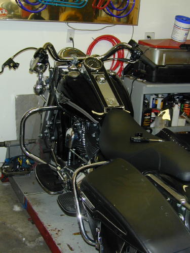

There’s an unwritten rule in the Code OfChrome that says, if you slip a set of highbarson any motorcycle you save it from mediocrity.There’s more, an evil punishment for this oftenillegal gesture towards the rebellious arts. Assoon as the unsuspecting rider throws his legover the saddle and reaches for the tall grips,his sideburns expand down the sides of hisface and a goatee springs forth from his chin.The cuffs of his t-shirt roll, and he begins tosmoke a pack a day. An treacherous grinspreads across his smoke tainted teeth, as ifa deadly rash, and before the week is out he’sleft his lovely religious wife and ravagedseveral other women. Hearts lie broken in histire-burned path. It’s an ugly sight. So what didwe do to the King next–Highbars to the stars.
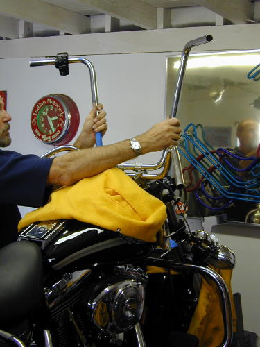
As soon as a date was set for theArizona Run I called Frank Kaisler, “We’ve gottwo weeks. Let’s install the highbars.”
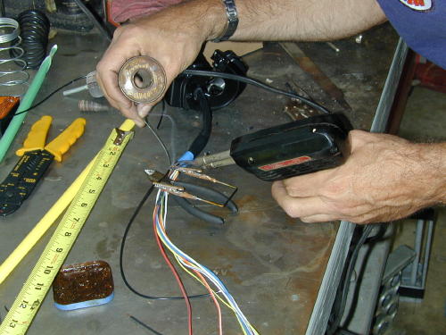
“You’re nuts,” Franks said, “but we allknew that. Let’s do it. Make sure you have aroll of thin 60/40 solder, soldering paste and awide variety of long shrink tubing from 1/8 to1/2 inch. Oh, and you can get a head start bydrilling holes in the bars for the wiring and aslot at the bottom for the wires to exit. Startsmall and work up to and beyond 1/2-inchholes.
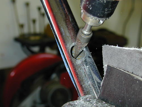
With multiple drill sizes and burr bits Iformed over 1/2-inch holes after holding thebars up to the bike and trying to estimate theposition of the grips. This is critical. I unboltedthe grips and measured the distance in fromthe end of the bars where the wires would runand noted the position of the wiring.
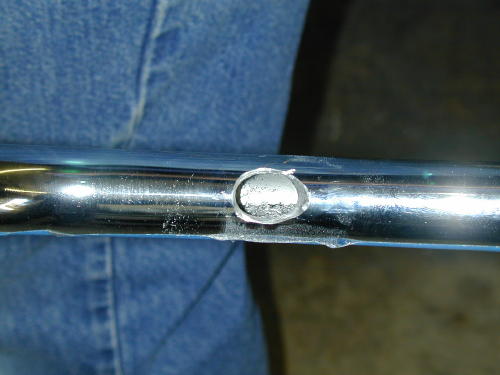
This was nervous work since it was notprecise. Even the slot at the bottom of thebars almost 2 inches long and 5/8-inch widehad to be carefully positioned not to put unduestress on the wires.
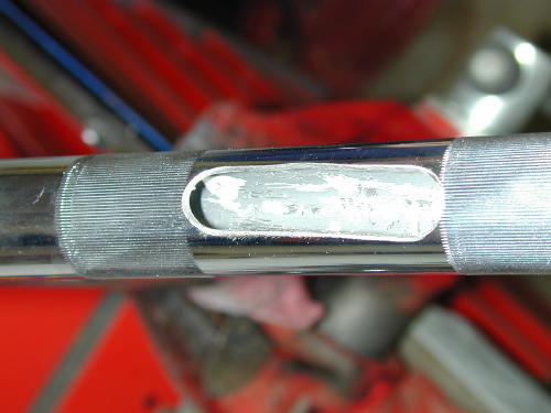
I took the riser housing off so I could seehow the wire looms and cables ran. WhenFrank arrived he brought along a sack full oftools that included emery bits and a dremeltool to smooth out the sharp edges particularlyon the inside.
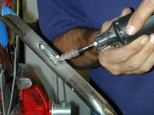
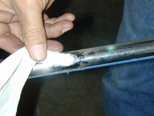
We quickly rounded out the edges of theholes so as not to cut the wiring. Frank usedhis trick of shoving a tissue paper in each holeto test for sharp edges or burrs. If it snaggedthe least amount we continued theedge-softening procedure. He also kicked meduring the process and reminded me todisconnect the battery.
Next we had to carefully strip theheadlighthousing and handlebars. To remove the riserhousing there are two screws adjacent to theignition switch (pop off the guide ring aroundthe ignition switch with a screwdriver), but thatdoesn’t do the entirejob. The headlight ring must be removed.Take the sheetmetal screw out of the bottomof the ring and then lift out and up. Thering is held by a notch at the top andsupported by a spring that will snap loose.When it pops free there are eight small blackscrews holding the headlight assembly inplace (the other silver screws are there toadjust the lens–don’t mess with them). Afterthey were removed theassembly came out easily but needed to beunplugged from the wire connection at therear.
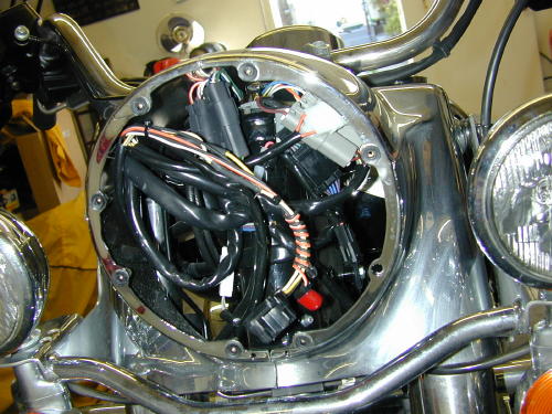
The wiring seems daunting, but it’s notbad and very organized.
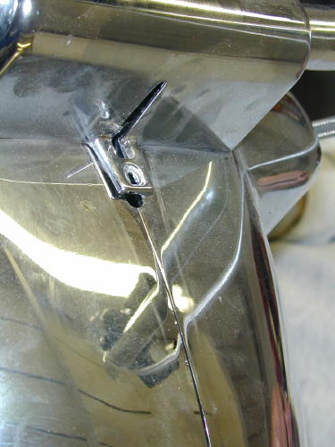
The last small bolt holding the risercover inplace goes in this hole under the nacelle strip.The strip hooks into the slot above it.
Then you need to reach up under thecowling and feel along the bottom for the verysmall nut that holds the bezel strip in place.Once the strip is removed, the riser cover canbe removed.
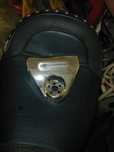
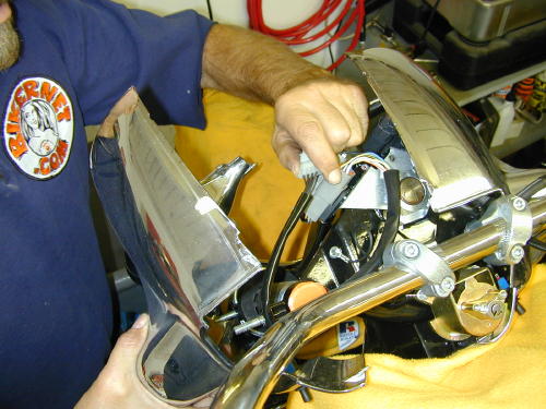
Here’s the cover removed. A lot of workto reach the handlebar clamps.
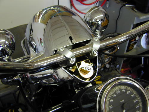
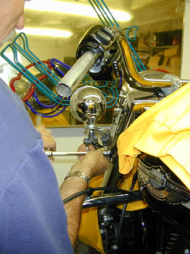
The two 5/16 dome nuts holding eachside of the bezel also hold the runners for thewindshield and the passing light bar, whichwe removed along with the front crash bar–Living dangerously.
Then the passing and turn signal light barwas removed for ever more, and the bezelremoved with the 5/16-inch dome nuts oneither side of the front end (make sure youkeep all the fasteners together including thewindshield runners). Set the chromed bezelaside somewhere out of harms way. That’s abig chunk of visible chrome.
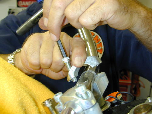
This photo reveals a handlebar clampbeing removed. It’s bullshit. We didn’t removethe handlebars until much later.
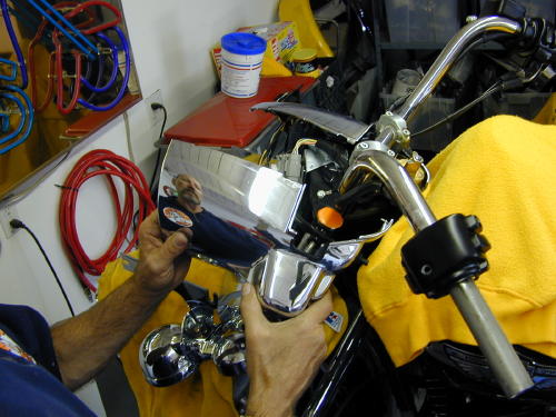
If you have a pal in the garage drinkingbeer and watching, get him to take shots ofthis process. If you must wait a week tore-install all this crap you may need areference guide and photos help a feeblememory. Or, of course, come to Bikernet andprint out this tech. Don’t forget to cover the tankand fender with something soft to protect themfrom scratches.
We noted that the electrical plugs on theleftside of the bike were different color from theright. We also noted their location and thedistance from the bars were measured beforeunplugging each connection to the handlebarswitches.
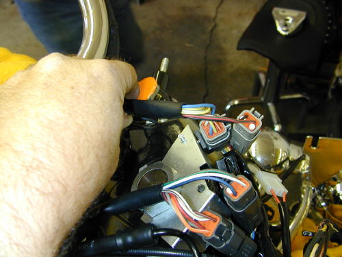
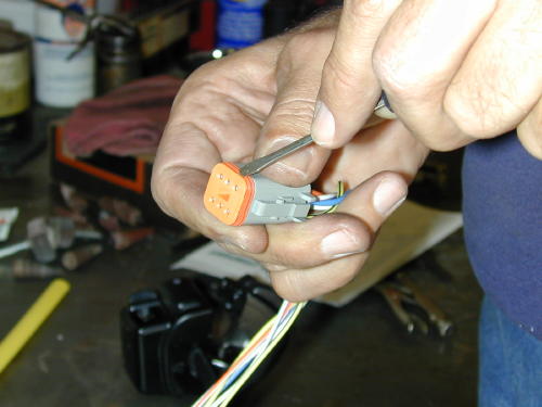
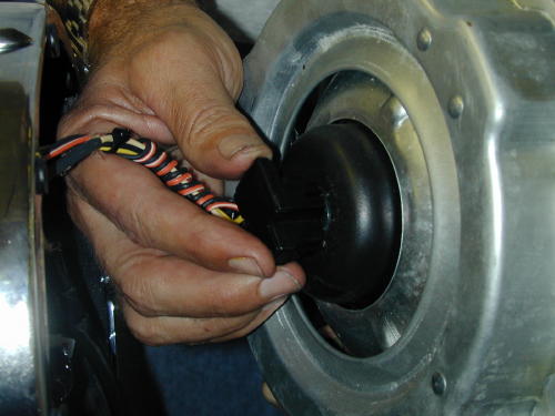
Don’t remove any wires before youdraw the diagram below. This cap performs acouple of functions. It seals the plug andinternally is pinches each wire lug in place.Once it’s removed a small screwdrive will pulleach catch away from each individual wire lugso it can be removed easily.
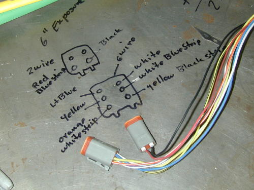
Check your diagram twice, no threetimes, before removing any wires.
We also noted the position of the throttlecables before removing the bars. Then thegrips were removed and switch housingsloosened so we could begin on the left side ofthe bars.
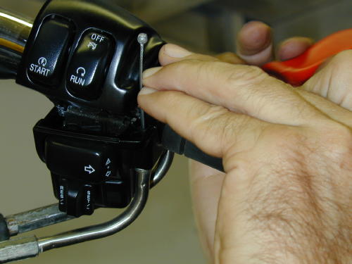
We handled the left wiring extensionfirst. This shot is of the right side and doesn’tshow a helluva lot, but it’s important. Toremove the throttle cable housings from thethrottle body it takes four miniature hands andtwo dinky screwdrivers to pinch the spring ringthat holds the cable in place. Be patient.
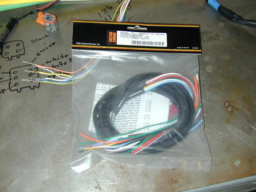
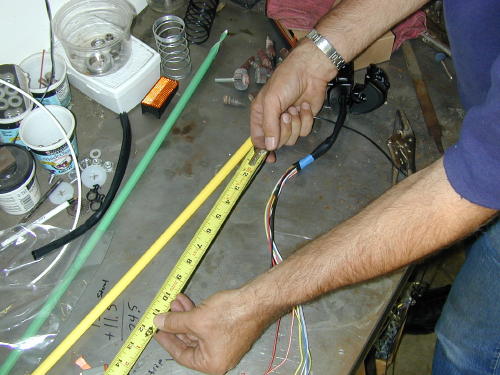
We measured the length of the wiresfromthe switches to the plugs, then compared thatmeasurement to the new highbars anddetermined that we needed to extend thewiring 13 inches to insure the proper length.Add an inch just for safe keeping. This aspectwas measured carefully several times.

Then the left switch loom was attackedfirst by drawing the back of the plug on thestainless bench top with a felt pen. We notedeach color coded wire and position beforeremoving the wires from the plugs. Do it fromthe back so you’re in the same position whenyou reinstall the wires.
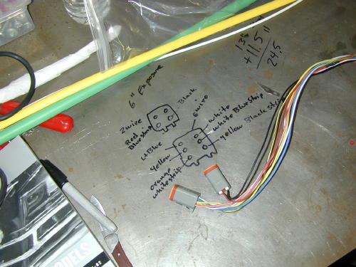
Sure, here’s another shot of a diagram,but it’s damn critical to insure the wiring iscorrect, so pay attention. Note, that we madeindications on the drawing to indicate the topfrom the bottom of the plug.
We added sections of 13-inch wirestaggered in the center of the loom so as notto stack junctions, and so we maintained theoriginal color coding. Each junction wascarefully striped 1/4-inch, soldered and sealedwith shrink wrap.
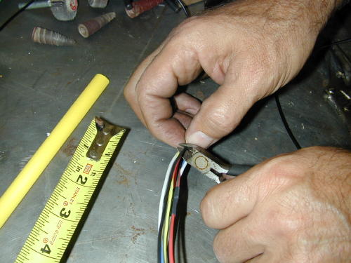
One shot we missed depicted thewires staggered. That’s also crucial so youdon’t have junctions bunched together.
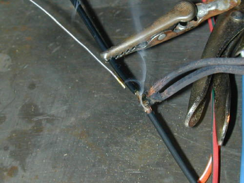
Note the handy wire connection holdingtool that Frank had made while working alonein his garage for ten years. Trying to hold theconnection together, while holding the solderand the gun is nearly impossible.
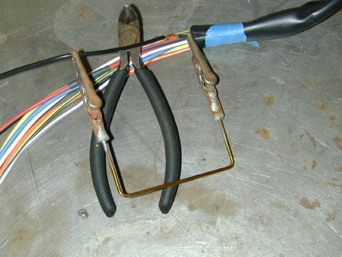
The Frank Kaisler, patent pending, wirejunction tool. Send $99.99 to P.O. Box 666,Hollywood, Calif. Send only rolls ofquarters.
He spoke to an engineer at one point whodidn’t cotton to twisting wires. He suggestedthat the wires be carefully mated straight onand soldered. The “Puerto Rican shrink wrap”as Frank refered to my colorful array of shrinktubing, was cut so that it would seal 3/8s of aninch on either side of the connection. Mostchunks of 1/8-inch diameter shrink wrap werea pinch over an inch long.
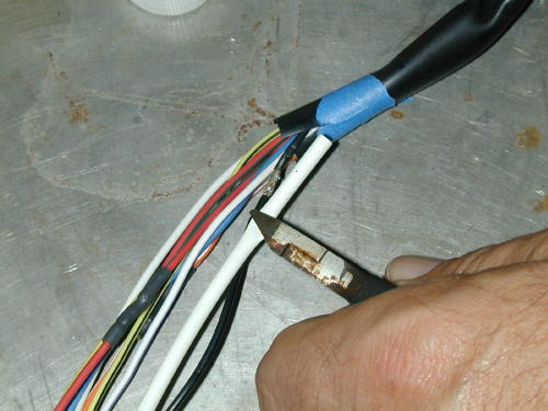
We also washed each connection withalcohol to remove the flux, which could harmthe wires or insulation, then with wet and drysandpaper, brushed any sharp edges thatmight cut through the shrink wrap.
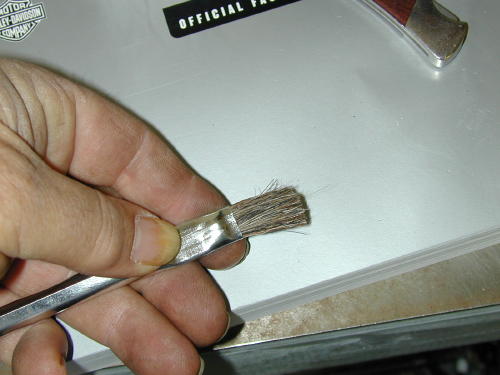
We cleaned the connections usingalcohol with this brush trimmed in half tomake the bristles stronger.
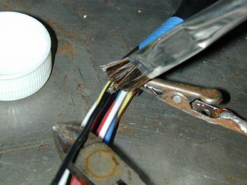
After each wire was carefully soldered andprepped we covered it with shrink wrap, thenusing Frank’s handy tool we heated the areaand moved onto the next stage.
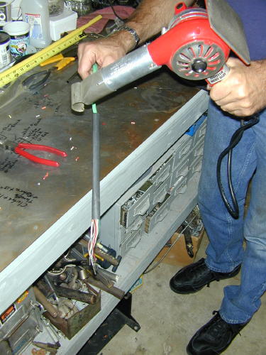
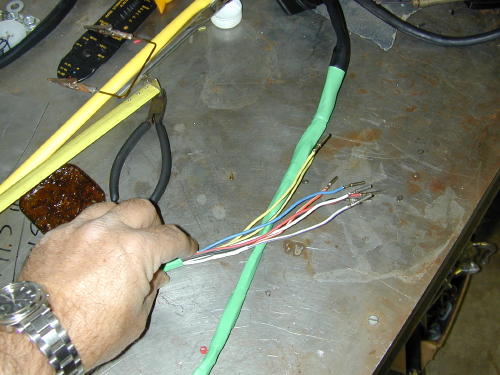
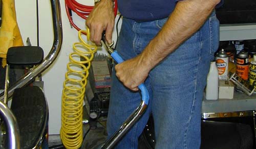
Then the looms were carefully coveredwithadditional 1/2-inch shrink wrap. Finally thebars were carefully blown out with the aircompressor and wiped clean before thelooms were fed into the grip ends of the bars(first we wrapped the pin connections withpainter’s masking tape and created a guidingpoint).
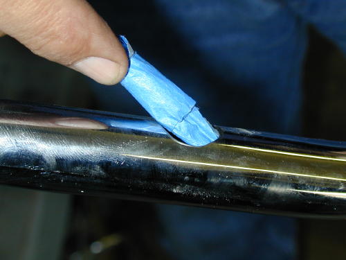
I used a painters masking tape to wrapthe connections and form a guiding point. Ididn’t want to use a tape that would requireawkward or violent stripping to remove it(which could damage the wiring).
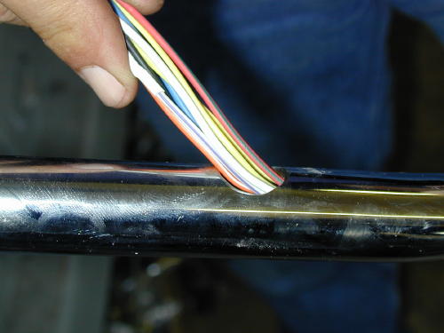
Feeding the wiring into the bars fromthe grip end.
Once carefully pulled through the bars andthe switch housings positioned, we beganthe process of installing the connector pins.
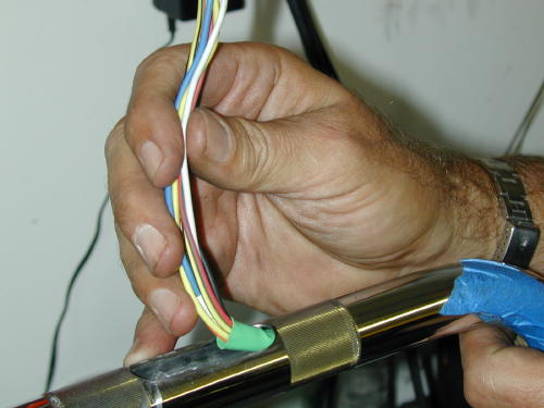
Gently pulling the wires from thebottom of the bars.
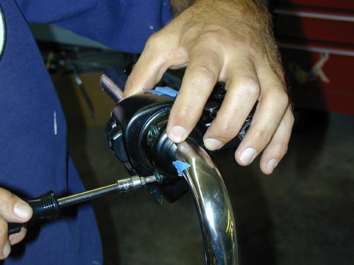
After making sure the wires are exactlyin the right position we snugged down the torxscrews, but not permanently.
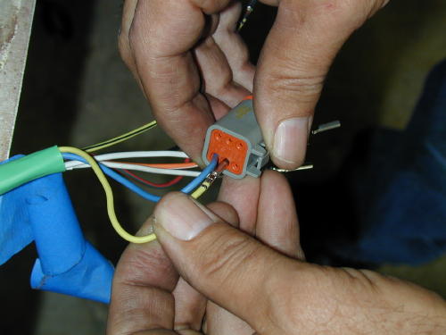
While refering to the diagram on thebench we carefully replaced the wires in thebottom of each plug.
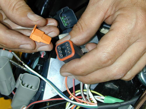
Note the wedged caps that force eachwire clip into a locked position.
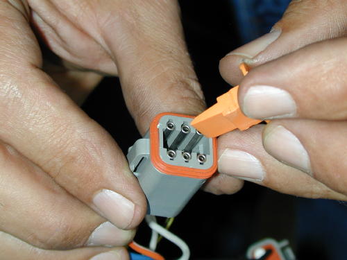
This depicts the same procedure fromthe other side of the bars. What a great shot,huh?
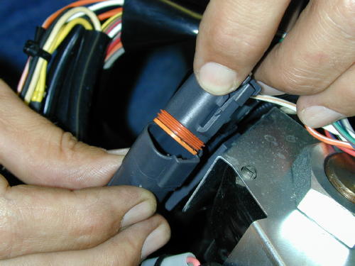
Only then could we snap the plug backinto place on the bike. Of course the plugcolors matched.
This was a nervous time. We hadextended 8 and 9 wires respectively (on eachside of the bars), carefully worked themthrough the bars and guided them out thebottom. As we replaced the plugs the sweatbeaded on my brow. Had I correctly solderedeach wire? Was each wire replaced in theplugs properly? Did I call a wire white withgray stripe, when it was actually white withblue stripe? It had taken almost four hours tocomplete the operation on the left side of thebars.
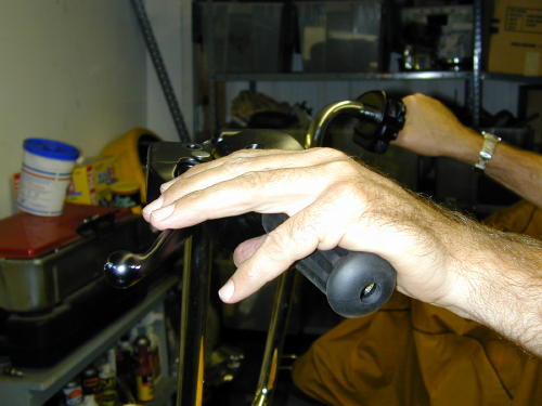
We put the levers in place just to checkthe position and see if we didn’t blow it. It wascool.
After a needed lunch break we tackledthe right side of the bars with the sameprocedure. Now with the wiring installed in thebars they were returned to the motorcycle. Iswung my leg over the 100th anniversaryCobra-styled seat and perched my ass down.Frank turned the ignition switch on, “try it out,”he said.
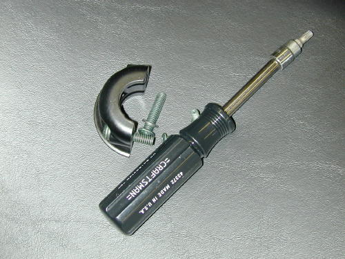
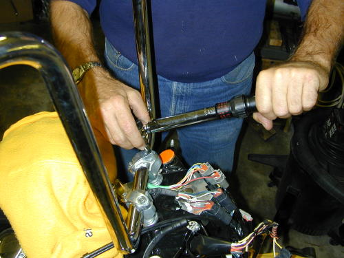
Torquing the bars down to 15 footpounds. Torque the front Allens down first,then the rear according to Pablo.
Continued On Page2
Road King 4/26/04
By Robin Technologies |


Over the last year we’ve tore into this classic 2003, 100th anniversary Road King. I figured I wanted a touring bike for the long haul. The notion was designed around maintaining the 100th theme, adding to the blackness and durability. I wanted a tough black bastard to ride, not detail or polish for shows. A bike for years to come. What could be better?

We kicked it off with light styling and safety accessories like a blacked-out dash, lowered shocks, rewired turnsignals, touring components and detachable back rests.

We worked with a dealer for more involved tech mods and performance enhancements. Our formula was designed around beefing the low-end torque with cams, Screaming Eagle heads, air cleaner and two into one pipes. I ran it directly from the lift to a dyno, for a comparison test, which resulted in 68 horses, an 8-horse increase and 76 pounds of torque, a 6-pound increase.


My old school notions leaned toward blacking out the king. If the frame had been another base color we might have followed it, but unity was the slogan behind design changes. I worked with Custom Powder Coating in Dallas as we stripped the touring model, inventoried the elements and sent them to the masters of powder (214)638-6416.

I rode over to Henry Figueroa’s Auto Restorations, a steel corrugated building on the wrong side of town. We removed the license plate holder and rear plastic fender tip. The filling and paint came from Henry (310) 218-9097. Henry filled the holes in the bottom of the fender and prepare it for George, The Wild Brush, to perform classic pinstriping magic (310) 488-5488.

I wanted to flame the bastard but paid homage to the 100th anniversary of H-D, reluctantly. We compromised and snatched the gold and silver (or gray) from the edge of the 100th tank band and expanded it to other elements of the King.

We installed a factory oil cooler and tested it on the road to Barstow, California. Every goddamn element was covered in techs right here on Bikernet. Keeping the oil at a resonable temperature is critical to long rang reliability.

Since I might ride the King to Sturgis this year and pack a Bikernet babe, we installed a detachable back rest for long distance runs.


“It could be flamed and raked,” Renegade shouted from behind his rigid, kicker-only, magneto charged Shovelhead.

H-D Lowered shocks — For coolness without disturbing the ride.
H-D Shock pump tool — For ease of modifying and checking ride ability for singleor double-up runs.
H-D Taillight/brake light mod — To turn the turn signal lights into brakelights for added stopping visibility.

H-D Digital dipstick — For ease of observing oil temps.
H-D Docking kit — For backrest and fender rack capabilities.
H-D 100th Anniversary Cobra style seat — For coolness.
H-D Blacked out dash panel — For coolness and lack of sun glare on the openroad–get it?

H-D Crash bar bags — For additional touring space.
H-D Mobil windshield — For low or high touring.
H-D Windshield bag — For windshield storage
Screamin’ Eagle Teardrop air cleaner cover–Style.
Screamin’ Eagle Heads–Enhanced flow and increased compression.
Screamin’ Eagle Air Cleaner Kit–Improve air velocity
Screamin’ Eagle Two Into One Touring Exhaust–Matching exhaust with heads.
H-D Speedo/Tach–More tuning information for the rider.
Screamin’ Eagle EFI turner kit–Tuning software.
H-D SE-203 cam set–Specific low end/mid range performance enhancement.
Goodrich Hydraulic lines and fittings–Extended lines for highbars.
Barnett’s Tool– Extended throttle and clutch cables.
Custom Chrome 16-inch High Bars–Changing the nature of the beast.

H-D black mag wheels and floating rotors with black centers–Adding to the blacked out look.
H-D fender brackets–Allowed the solid black Street Stalker fender to be bolted to the touring front end.
Screamin’ Eagle teardrop turnsignals and the narrower light bar–All style
H-D fender, license plate mount–Moved the bracket out of the way.
H-D New oil cooler for 1999 and later touring models–essential to cool the King.
H-D custom billet tab for the rear of the stock seat–We needed an extra one.
H-D Front and rear detachable docking hardware kits–Allows for detachable touring accessories to be mounted
H-D Lower backrest/sissybar–Designed to pleasure the ladies.

H-DClassic hexbolt covers and stainless Allen caps to begin an engine detailing process.
H-DClassic Chrome Axle caps–Factory styling additions that prevent chrome shop runs.


