Amazing Shrunken FXR 12: Tools And Linkage
By Robin Technologies |

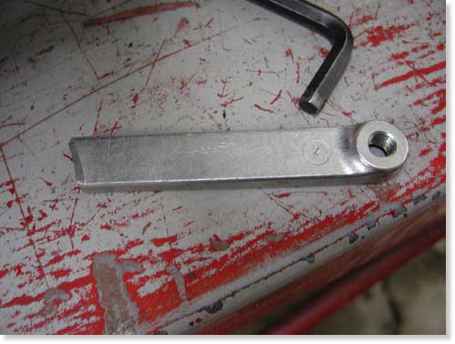
The stock tranny linkage cut to work as our brake linkage.
A week ago I worked on the brake controls with some success. After fabricating a mastercylinder bracket and actually drilling the holes in the proper location, it wouldn’t work. I needed to turn the master cylinder upside down. I called Frank Kaisler to confirm that it was a remote possibility, it was. I cut another chunk of steel plate, drilled the holes again and dug through drawers to find a pushrod. Nothing.
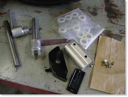
Parts and pieces we used to cobble together brake linkage.
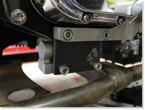
The master cylinder in place upside down under the tranny.
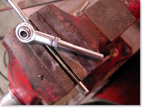
The stock stainless shift rod cut for a master cylinder pushrod.
I used a stainless steel shift rod unit for lots of adjustment, but had to grind/taper the end to fit. I also used the transmission shift lever for the connection. I cut Giggie’s brake axle to length and sliced the tranny shift linkage. Then I welded the linkage to the axle. That was a mistake. I should have machined the pieces to fit together, but it will work. The other end of the linkage was the perfect mate for the shift rod I cut and fashioned for the handmade master cylinder push rod. I lucked out. I think it’s cool.
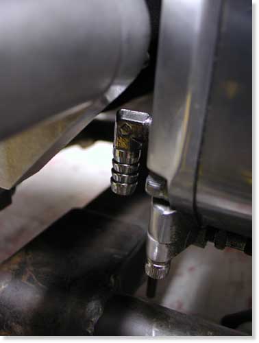
The inlet oil fitting had to be moved to make room for the brake linkage.
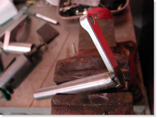
Here’s the tranny-gone-brake linkage welded to the brake axle.
That was last weeks endeavor. This week I stumbled. It all began with a set of exhaust I fabricated, from bits and pieces of other exhaust, for the Amazing Shrunken FXR. They worked out all right until my humble associate, Nuttboy, was assigned to grind the welds. Ya see, I held one piece of pipe against another and tacked them. The mating surfaces were not aligned perfectly, so when Nuttboy unleashed the Makita grinder to round off the welds he cut right through the pipes forming cavern-like gaps.
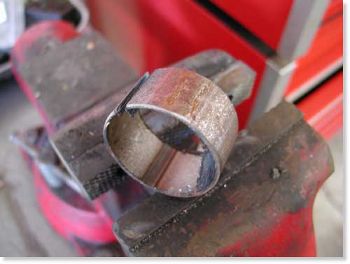
Kustom fab uses pipe inserts to hold pipes aligned securely for welding.
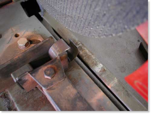
I had to enlarge the slot to make the insert fit.
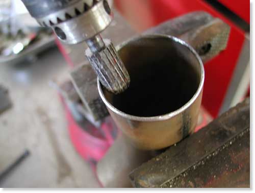
The insert won’t slip into place with burrs in the pipes. I had to grind them clean.
Lots of builders in the industry make their own one-off custom exhaust, so I started asking around about tools. Most don’t have tube benders, so they follow the same strict regime I did. They piece exhaust systems together using bits and chunks of other systems. One company will ship you a kit of various bends to work with. I inquired as to how shops held two chunks of tubing together in order to MIG, TIG or even gas weld pipes. The information highway opened up to me. Roger from Kustom Fab in highway takes a 1-inch section of like pipe, slices it (so the O.D. shrinks) and shoves it in one section of pipe then in the other. Simple system that adds strength but reduces the I.D.

Here’s the insert in place. It works well and adds strength but will restrict exhaust flow.
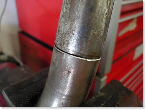
This system also makes welding easy.

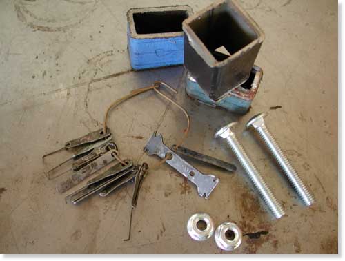
Some of the junk I dug up to kick-off my pipe clamp tool experiment.
Another builder told me of a C-Clamp arrangement using angle iron to lock chunks of pipe in-line. Scott from Chica’s explained a small unique tool that pulls the segments of pipe together using feeler gauge thin material. After tack welding the pipe segment, the clamp is loosened and the feeler gauge material slips out. Irish Rich pointed out that large hose clamps and chunks of angle iron work fine to hold pipes for tacking.
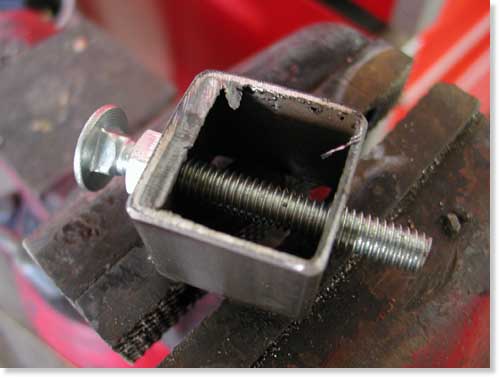
This was my bullshit attempt at building this tool.
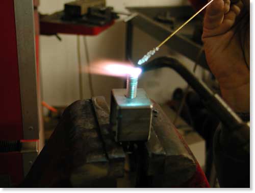
I brazed the feeler gauge to a nail and the nail to the end of the bolt.
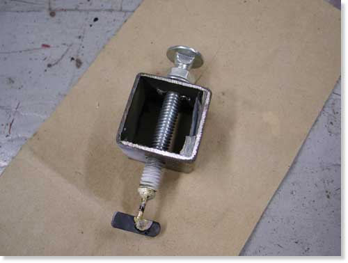
Here’s the completed tool. It looks better than it works.
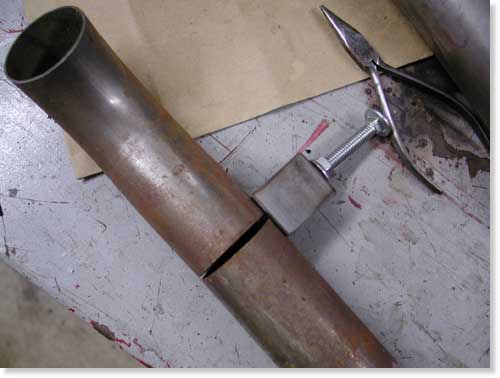
This shows the clamp in place. In order for it to work properly a notch needs to be ground in the pipe for the nail shaft, which is thicker than the feeler gauge.
The guys at Chica’s also told me about a wide stainless hose clamp with slots or holes that can be used to hold two tubes together during the tacking stage.
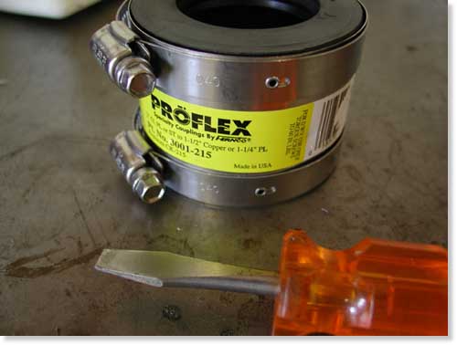
I found this puppy at Home Depot and thought I had hit gold.
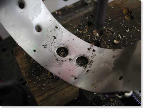
I drilled the stainless strap with a small drill then 1/2-inch for tacking room.
Then Fab Kevin clued me into Holley, the hot rod car part builder, who makes a sleeve that holds two pipes in alignment for tacking. I looked them up on the Internet.
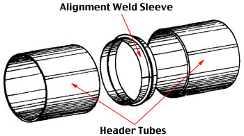
Our “Alignment Weld Sleeve” allows the fabricator to align, hold and weld two pieces of mild steel tube without help. Because no rod is needed, the welder has a free hand. The “Alignment Sleeve” assures a perfectly aligned joint with no weld slag inside to reduce the tube diameter and restrict air flow. Perfect alignment and just the right amount of welding material results in a very professional looking weld. Weld Sleeves are packaged 20 sleeves per bag.
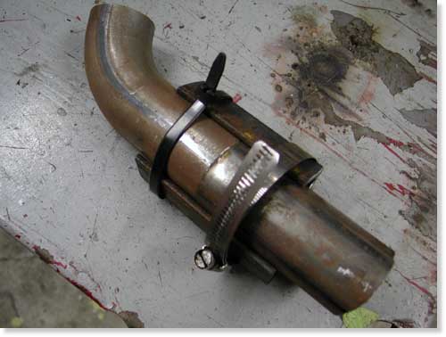
See, I couldn’t find a hose clamp to do the job. I need another hardware store run.
This is where the story runs astray. I followed each veteran’s suggestion and began to fabricated every exhaust pipe alignment device known to man. I cut, brazed, hit Home Depot, bought clamps, hoses, sliced my only .013-inch feeler gauge, dug through drawers and took photos along the way. No shit, I fucked up every tool design suggested.
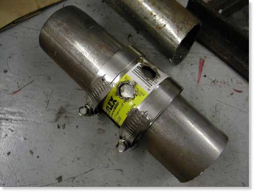
This is how it’s supposed to work. Unfortunately the clamp I bought was too large.
I didn’t have two hose clamps that would pull the angle iron hard against the tubing. The wide stainless clamp notion was golden, but I bought the wrong size at Home Depot. The feeler gauge routine was followed to the finish, but my tool doesn’t work without a notch snipped in the pipe. The C-clamp notion is too involved for my thinking so I decided to buy two clamps and modify them. Of course I didn’t have two spares to screw with. And finally the perfect solution from Holley was unavailable from my local auto parts store. I’m forced to buy their catalog.
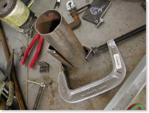
This is the C-clamp notion. I’ll build it after I hit Home Depot again.
If tonight you called and offered me a cool million to build an exhaust system, I still don’t have the tools. I need to hit Home Depot again. I almost fired myself last night, but you get the idea.
–Bandit

Amazing Shrunken FXR 11: Mid Controls
By Robin Technologies |

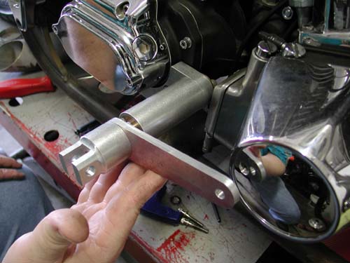
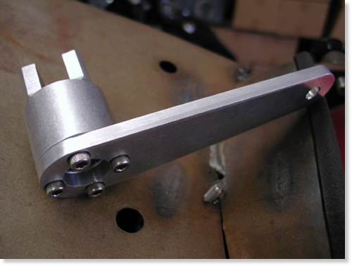
Shrunken FXR mid-controls by Giggie at Compu-Fire. Note: we need flat-headed Allens.
Giggie our master machinist from Compu-Fire rolled up to the Bikernet Headquarters last Saturday. We haven’t seen him for months due in part to his work on new starting systems for the custom market. They are dancing through the final development stages of a system configured to drive off the crank shaft of the motor with a 60- to-one ratio compared to stock 48-to-1. That will leave the area about the tranny available for custom applications or lower seat heights.
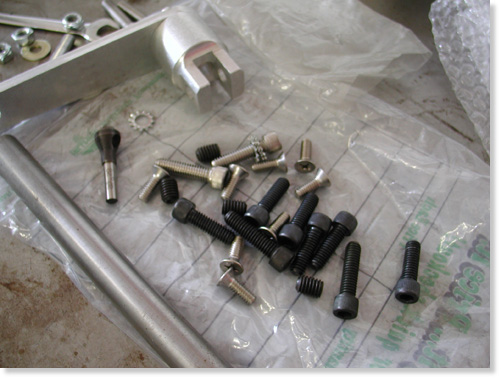
Giggie brought some wrong fasteners but lots of them and counter-sunk drilling tool.
Currently Compu-fire is soon to release a standard starting system, the Gen-2 HT, with 33 percent stronger magnets, 6-roller longer clutch (32 percent longer) with 30 percent more cranking while drawing the same amps from the battery.
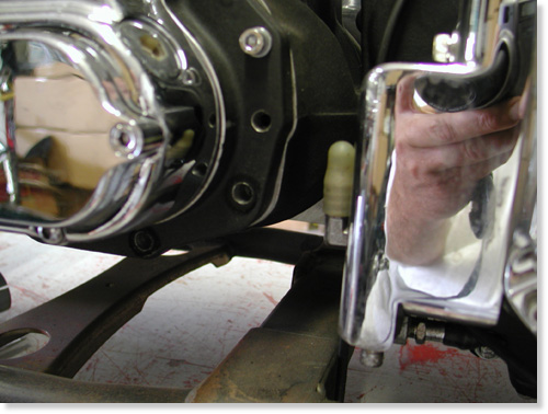
Here’s the tranny without the brake pedal components. There’s some tight tolerances going on.
I spoke to him about our cooling debate and here are some of his thoughts. “You want your oil to run at a minimum temp of 205 to eliminate water vapor or condensation that accumulates in oil,” Giggie said. “At 240 to 260 degrees petroleum based oils begin to break down, although synthetic lubricants could be good to 360 degrees. I have my doubts.”
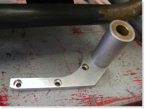
Base bracket to be bolted to the transmission.
Giggie developed an oil cooler for his FLH that kicks on at 220 degrees and off at 200. It has an in-line thermal switch continuously reading oil temp. He installed his cooler in a box with vents and two small electric fans wired to the thermal switch (to cool while idling).
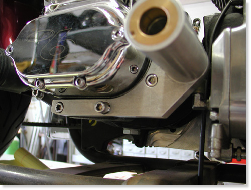
Giggie’s mounting bracket bolted in place.
Regarding our project Giggie dropped off hand machined mid-controls for shifting and rear brakes. Next, we must buy a H-D slave cylinder with remote reservoir with a built in brake switch. We will hide the reservoir behind the oil bag and design a bracket to hold the slave under the trans.
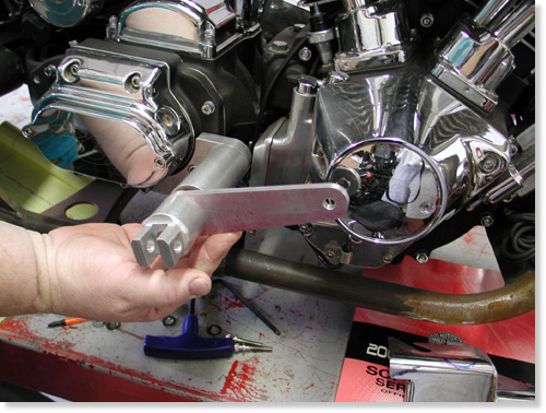
This shows the pedal and shaft in the mounting bracket.
Giggie will supply us with four more bushings to run behind the shift and brake levers, two 1/8-inch thick and two 1/2-inch thick, to allow us variable spacing away from the engine pulley or point cover on the cone.
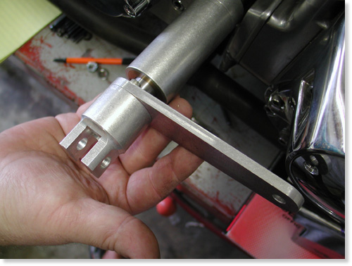
Giggie will supply two different bushing to be installed between the brake lever and the mounting sleeve. We’ll need the space to clear the point cover.
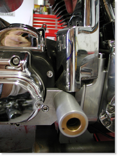
Unfortunately the sleeve hit the oil pump cover. We may be able to remove enough material or just polish the pump. The oil pump inlet fitting will also need to be turned down. It’s close.
With the bushings in hand we can develop our final linkage behind the BDL belt drive plate and Giggie’s tranny plate to connect with the slave piston.
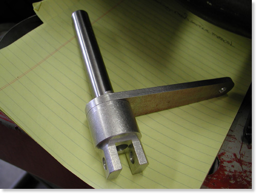
In both cases we need to cut and machine the other end of the shaft, depending on the linkage.
I’ve decided to remanufacture the exhaust system which is now a tight fit around the new brake linkage. Giggie also machined the foot peg mounts to accept any standard, pivoting foot pegs.
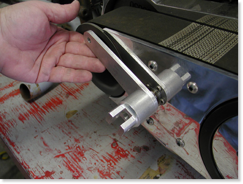
The slick new mid controls for shifting slid through bushings machined into the BDL outter and inner covers.
Next we need the bushings, slave cylinder and a day in the garage hammering and welding a new set of pipes.
–Bandit

Back To Part 10, Page 2
5-Ball Factory Racer Part 8: Baker 5-Speed Extreme Kicker Kit Install
By Robin Technologies |

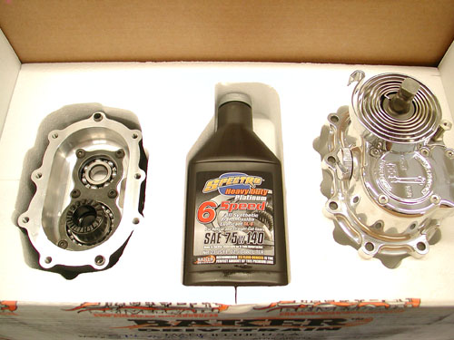
This is one of those shop quiet times installations. You want to make sure all the stars are aligned for this one. Stroll outside the shop with an icy Corona and look to the heavens for inspiration. Sturgis was looming and since this bike was all about vintage I needed a kicker system. I've installed the Muller system from Germany. I've wrestled with a custom chrome 5-Speed kicker transmission into my 1956 Shovel, a very rare motorcycle, so I'm not without some experience. But Baker took the kicker development to a new stronger level, which involved removal of the entire gear set, replacing the trap door and more. I never held an entire gear set in my nervous hands, like a man holding his newborn baby.
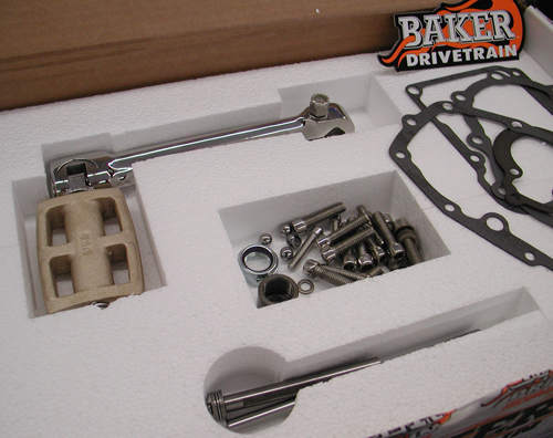
Having an inexperienced wrench write a tech tip has it's ups and downs. He could fuck up everything, but on the other hand he'll write about it, so you won't make the same bullshit mistakes. I know first hand that if you've performed the same task a dozen times, the details become second nature and usually are not documented properly. There's my Zen notion for the day, oh humble gods of Baker Drivetrains.
On top of Sturgis pressure, and the unknown Galaxy of emotions, my Epson Camera was acting up. It's been the best for shop techs, beyond Canon or Nikon, but that's another story. I'll scramble my thoughts between data from the Baker team of experts.
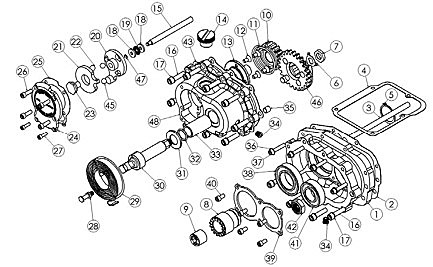
First, here's a list of the applications available for this modification:
• 1990-2006 Softails™, FLT/FLH™, and FXR™ models
• 1991-2005 Dyna™ Models
• BAKER DD5 complete and builder’s kits.
IMPOTANT NOTES TO BE CONSIDERED
• BAKER Factor 5 Kicker will not clear most stock exhaust systems due to the extended length of the transmission door and kicker. Most true duels usually fit FLT/FLH models. Rear pipes that route away from the right side of the transmission usually fit.
• The kicker arm will not clear the stock right side passenger floor board on FLT/FLH models. Installation of foot pegs or smaller footboards are required.
• Twin Cam models require installation of a cam-based ignition. See BAKER 2008-2009 Supplement for ignition alternatives or consult a BAKER sales tech.
• Fuel injected models require retrofit to carburetor.
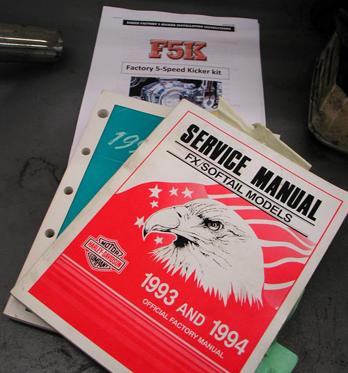
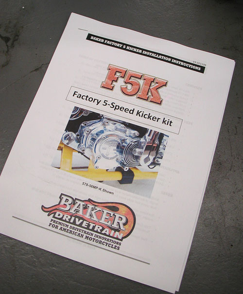
GETTING STARTED The BAKER Factory 5 Kicker kit is designed to be easily installed by any competent mechanic or dealership technician. Having your H-D factory service manual is required for this installation as it is referred to in many sections of the instructions. While this kit is made to be as easy as possible to install there is no substitution for experience. To install the F5K kit, disassembly of the transmission down to the gearset is required. We recommend reading through these instructions, to the end, before proceeding with installation process.
TOOLS, RESOURCES, REQUIRED PARTS
• Factory Service Manual For Your Motorcycle
• Factory Parts Manual For Your Motorcycle
• Common American sockets and open end wrenches
• ToolB-56, BAKER Inner Race Service Kit or H-D equivalent
• Hydraulic Press
• In-lbs Torque Wrench
• Brake Bleeder Pump (for hydraulic type)
NOTES: HYDRAULIC VERSION ONLY
To complete the Installation of the hydraulic F5K, the following parts will have to be procured to complete the job:
• Hydraulic Fluid, BAKER Recommends: H-D Dot 5 Brake Fluid, PN 99902-77
• Correct length AN -3 Brake Line
• 10mm Banjo Fitting & washers for both ends of brake line
• 3/8”-24 Banjo Bolt for the side cover end of the brake line
• 11/16” Diameter Bore Hydraulic Clutch Lever Assembly or H-D
GEARSET REMOVAL
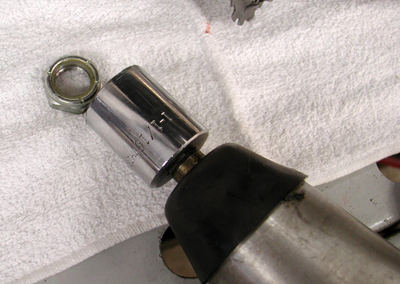
To remove your existing gearset, refer to your Factory Service Manual in section 7, Mainshaft/Countershaft removal. Follow the trap door/gearset removal procedure. Hint: with the stock side cover off, remove the nyloc jam nuts from the ends of the shafts BEFORE the trap door/gearset assembly is drawn out of the transmission case. A ½” impact gun works really keen for this task. Leave the main drive gear in the case.
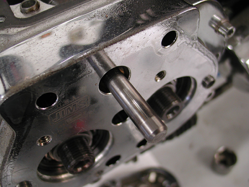
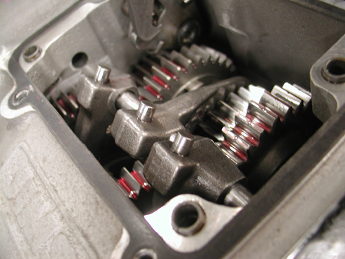

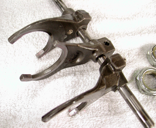
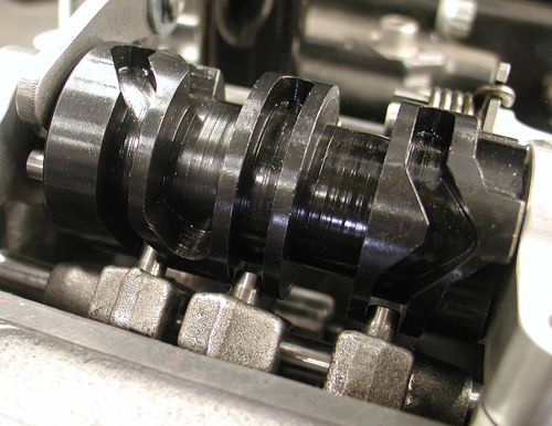
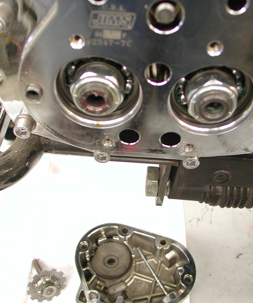
The top needed to be removed from the tranny, then the shifting drum (4 Allen bolts). With the front of the transmission removed some shifting fork shafts will slip out through the trap door in the front. Sometimes the sprocket or pulley can be removed and there's an Allen plug under the sprocket, in case the drap door doesn't have a hole in it.
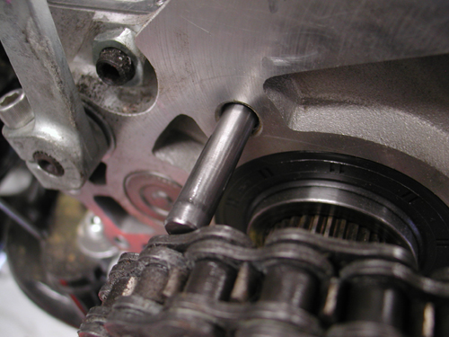
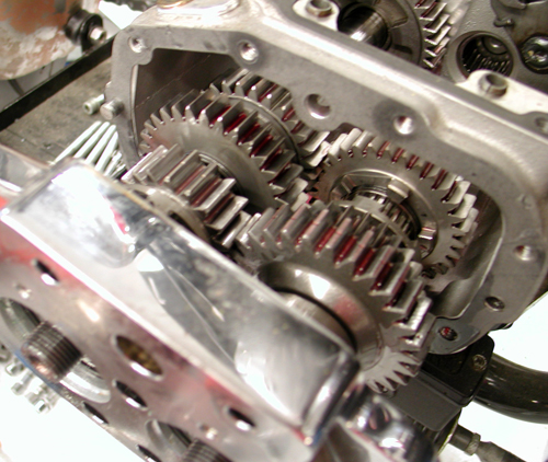

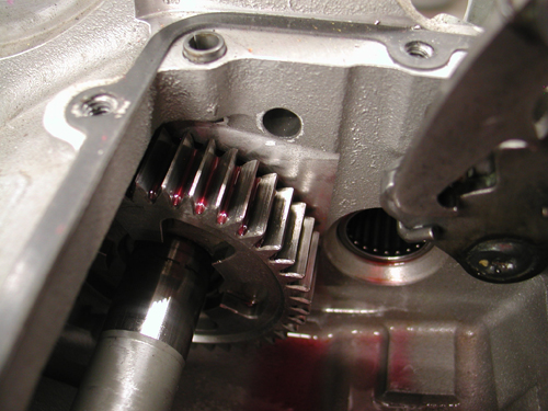
DISASSEMBLING GEARSET
Once the trap door/gearset assembly is out of the transmission case, put it on a soft towel on a clean bench. If that pesky right ‘C’ dowel is stuck in the door, remove it by tapping it through with a hammer and a punch or pulling it through with a pair of vise grips. This will allow the gasket side of the door to sit flat on the support beam of the hydraulic press.
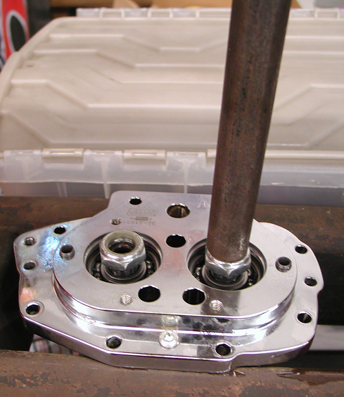
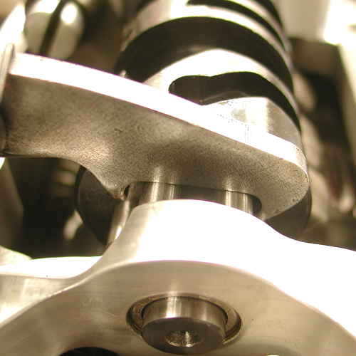
With the gearset facing down and the gasket side of the door of the support beam of the hydraulic press, press the end of the mainshaft down 1/8” and then do the same to the countershaft. Alternate pressing on the ends of both shafts (1/8” at a time) until the shafts fall out.
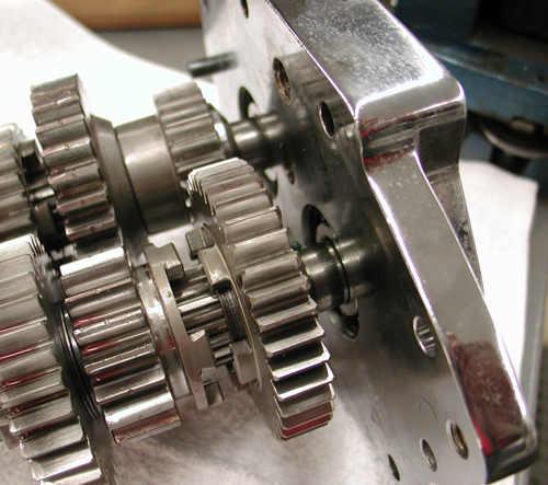
IT IS VERY HANDY TO HAVE A SECOND PERSON CATCHING THE SHAFTS AS THEY FALL OUT.
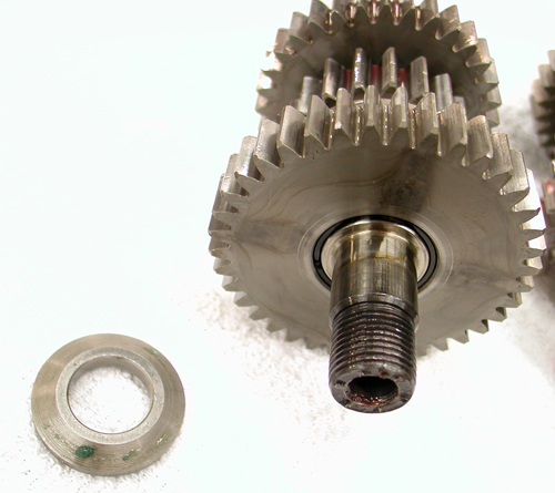
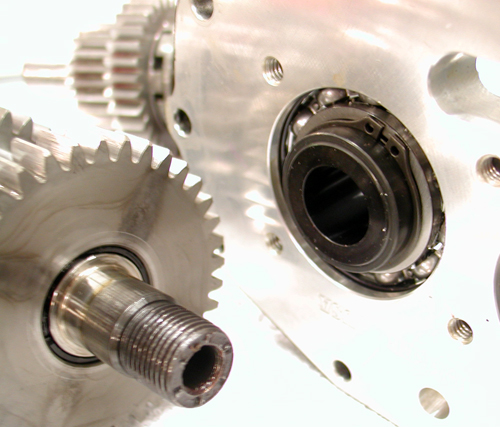
Do not allow the shafts to fall and hit the ground. Remove the conical thrust washer on the mainshaft as the ratchet hub (PN 308-5) will replace this part during the re-assembly process. Keep the stock conical thrust washer (the one without the step on the back side) on the counter shaft. Put the ‘prepared’ gear clusters on the soft towel on the bench.
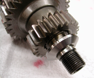


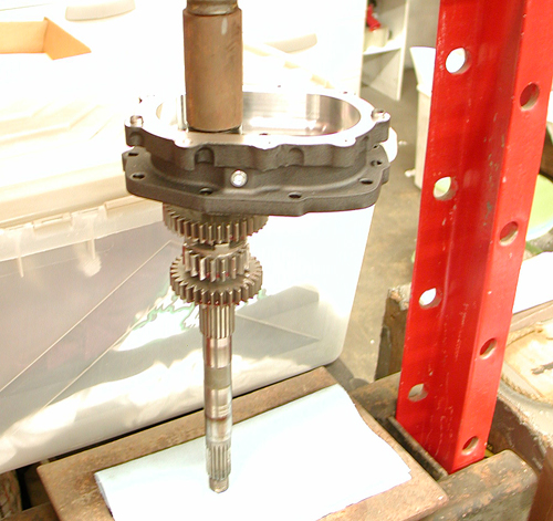
BEARING DOOR ASSEMBLY
1.) Remove the Factory 5 Kicker bearing door (PN 1-5SK(P,R,B)) assembly from the package. Clean your mainshaft and countershaft threads with lacquer thinner and dry them completely before pressing the shafts into the door.
Now take your mainshaft assembly and support it vertically in the press with the clutch end of the mainshaft at the facing down. Insure that the cage bearing is still on the cluster with first gear around it. Now take your Factory 5 Kicker bearing door (PN 1-5SK(P,R,B)) assembly and press the mainshaft into the ratchet hub (PN 308-5) while using the ratchet hub (PN 308-5) as your press point (figure 2).
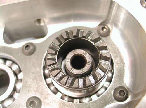
Make sure your mainshaft is perfectly vertical before pressing it in, damage to threads could incur if not vertical. Remove assembly from press. Apply thread ‘Red’ thread lock to the mainshaft retainer nut (PN RV-7050) and torque to 45-55 ft/lbs.
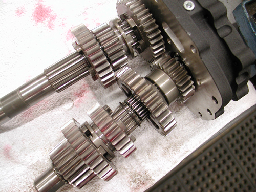
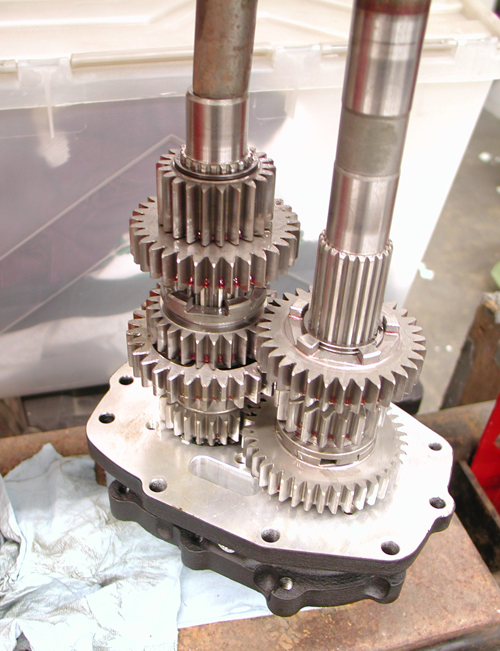
Once the mainshaft is parallel with the countershaft place the countershaft press tool on to the countershaft bearing in the assembly (see picture). Slowly press the countershaft into the bearing door making sure all the gears spin freely. Once the countershaft is seated, clean the threads with lacquer thinner and blow dry completely. Apply ‘Red’ thread lock to the countershaft retainer nut and torque to 45-55 ft/lbs. Your bearing door assembly is complete
GEARSET INSTALLATION
1.) Refer to your Factory Service Manual for proper gearset installation.
2.) You will need to use the supplied fork rod (PN 122-56K) for installation.
3.) Replace the bearing door assembly with the supplied gasket (PN 35652-79B).
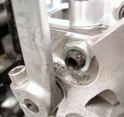
4.) Once the gearset is in the transmission case. Use the four supplied 5/16-18 x 1-1/4 SHCS (PN 73496) and 5/16 washers (PN 6100) in the lower four holes of the bearing door. Using ‘Blue’ thread lock, torque the bolts to 13-16 ft/lbs. Install the four supplied.
¼-20 x 1-1/4 SHCS (PN 73463) and ¼ washers (PN 609SS) in the upper four holes of the bearing door. Using ‘Blue’ thread lock, torque the bolts to 7-9 ft/lbs (84-108 in/lbs)
5.) Install your top cover per your Factory Service Manual using the supplied top cover gasket (PN 34904-86C)
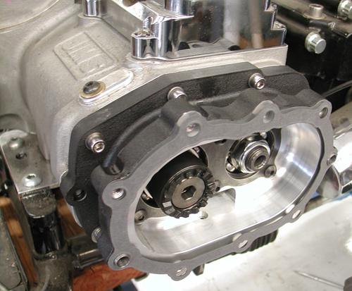
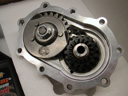
CABLE TYPE KICKER COVER INSTALLATION: PN 578-56M(P,B,R)-K Refer to your Factory Service Manual to remove your clutch cable from your side cover ball and ramp assembly.
1.) Place the side cover gasket on the two 10mm dowels (PN 16583-00) on the bearing door assembly.
2.) While making sure the ratchet gear (PN 310-56K) is still retained by the kicker crank gear (PN 33350-56), place the side cover on to the two 10mm dowels (PN 16583-00). While holding the cover in place take the nine supplied 5/16-18 x 1 ¼ SHCS (PN 73496) with 5/16washers (PN 6100) and apply ‘blue’ thread lock to the threads. Now torque the fasteners to 13-16 ft/lbs (156-192 in/lbs).
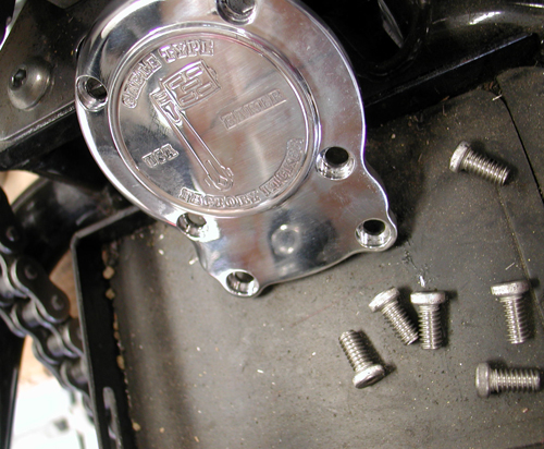
3.) Remove the six fasteners holding the ball and ramp cover on. Remove the ball and ramp cover and gasket at this time as well.
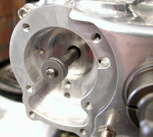
4.) Install the supplied clutch throw out rod (PN 125-5R) at this time through the pinion gear quill (PN 585-5)
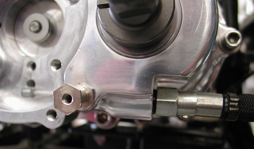
5.) Thread your clutch cable into the side cover. Loosen the clutch cable adjustment all the way so there is maximum cable exposed in the side cover.
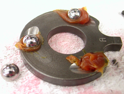
6.) With the cable fully extended in the side cover take the supplied ball and ramp assembly and slide it over the cable. Install the clutch cable ferrule
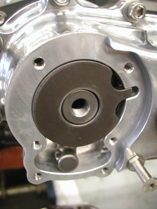
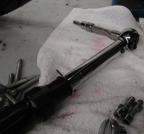
9.) Using ‘Blue’ thread lock, install the six bolts. Torque the four ¼-20 x ¾ (PN 25C50KLHS) to 7-9 ft/lbs (84-108 in/lbs). Torque the two #10-24 x 5/8 (PN 10C50KLHS) to 4-5 ft/lbs (54-60 in/lbs).
KICK ARM INSTALLATION
1) Install the kick arm on to the kicker crank gear shaft.
2) Tighten the pinch bolt on the kicker crank gear shaft so that there is no sloppy movement in the kicker arm assembly.
3) Either with your hand or leg, ‘kick’ the kick arm and run it through its motion to make sure everything is working properly.
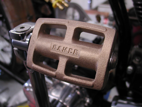
FINAL ASSEMBLY
1.) Install your primary and adjust your clutch per your Factory Service Manual at this time.
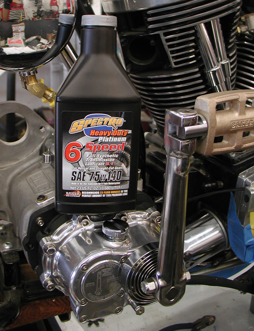
2.) With the bike vertical fill your transmission with the supplied 23oz. bottle of Spectro™ 75W140.
3.) Follow your Factory Service Manual to finish assembly on your motorcycle.
4.) Your BAKER Factory 5 Kicker installation is complete
For any installation or service questions, please contact our BAKER technical department toll free 1-877-640-2004.
Hang on for the next installment. Final assembly will begin with a BDL primary install, a Spyke alternator/regulator system, and we're getting ready to ride.
You'll see George's pinstriping, Tony's powder coating workmanship and my sloppy wiring.
–Bandit


Custom Chrome Goliath Kit
By Robin Technologies |

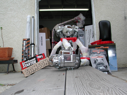
This shows just a fragment of all the parts involved.
Hang on. Here comes a complete build of a custom CCI Goliath Bike Kit. We built this 100-inch Rev Tech monster in nine days. The bike was assembled to promote the Annual Beach Ride, at the Queen Mary in Long Beach, through the efforts of Custom Chrome, George Hayward and Bikernet.com. We assembled the bike in the Bikernet Headquarters for the children’s charity ride. It was also featured in three issues of American Rider, but this is the extended, unedited version with charts. Before we get started, I want to add an editorial note. If you read this and want to add something, don’t hesitate. We can change the text whenever we goddamn want. If we missed something, you have a special tool, a correction or want to point out what a bunch of baboons we are, don’t stop, send a Your Shot. Let’s hit it.
“What the hell,” Nuttboy mumble, “what did you volunteer me for?” He scratched his butt, with a 9/16 open end wrench, as we loaded box after box of components into the garage. If CCI could somehow ship the components without the retail packaging, they would save a fortune. We had a truck load of plastic peanuts, plastic bags and cardboard.
The Goliath is a complete 100 inch, Rev Tech powered Softail kit. It comes with every nut and bolt. “And a few extras,” Nuttboy chimed in distractedly. Also included was a Softail manual and a Softail Parts book. We also referred to the Tim Remus book, “How To Build A Kit Bike”, from Wolfgang Publications.
“The Remus book was the most help, but there were big gaps in information,” Nuttboy grumbled. “We often had to scan the photos in the book in a fleeting effort to figure out a procedure that wasn’t described.” Maybe this series of articles will help.
The entire bike was built in a garage using normal hand tools. A professional shop came in handy on only two occasions: Pressing the clutch together, tire/wheel assembly and balancing.
The frame, wheel rims, and miscellaneous parts were powder coated by Custom Powder Coating in Dallas (214) 638-6416 to match the hue used by Santini Paint (714) 891-8895, for the sheet metal.
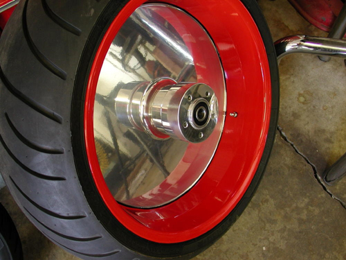
Here’s the massive rear wheel. It was powder coated red on the rim, then clear powdered. Finally George, the Wild Brush, finished the edge with a wide stripe.
“Violent Red I’d call it,” wise-cracked Nuttboy, “it looks hot enough to fry your bratwurst.”
We made sure the tank was pressure tested and sealed at the painter’s. We organized the parts as best we could and once the powder coating was returned Nuttboy shaved off the paint and tape where the motor mounts and tranny mounts were located. Dallas handles frames for American Iron Horse, so they know what to mask, which saved time. Nuttboy started checking the surface around the neck and beating the cups into place with a brass hammer and a massive punch. They must be pressed in completely.

We tried to organize the parts. This was the electrical stack.
We cleaned the area around the cup area on the neck to make absolutely sure the cups would seat entirely. That’s critical. If the cup seats more while vibrating down the road the front end will loosen and add to crucial elements that could lead to a high speed wobble.
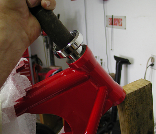
We used a 20-year-old Bikernet punch to drive the cups home. Make sure they’re aligned properly.
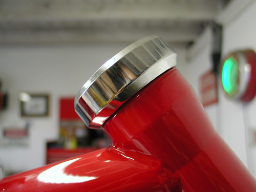
You can tell by the changing tapping sound that the cup is fully in place.
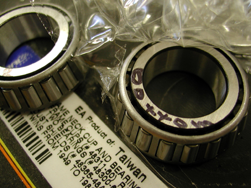
Note the markings to keep matched bearings and races together.
We separated the cups from the bearings but made sure to note which matched bearing fit in which cup, for the most precise fit. Nuttboy pounded the cups in place with a dab of grease to prevent jamming inside the neck.
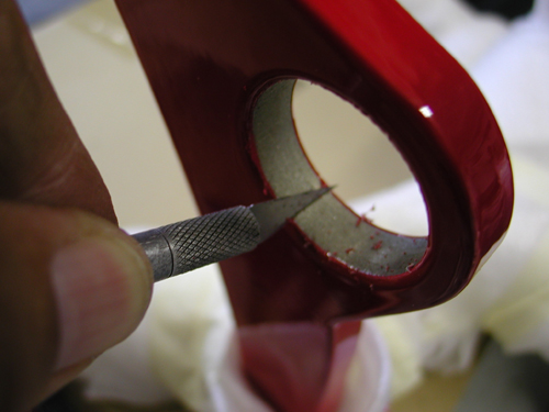
Custom Powder Coating did a fine job of taping off the bearing and motormount areas, but each one needed the edges cleaned.
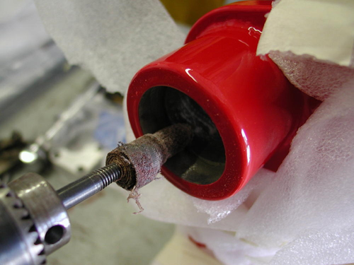
This emery bid worked wonders to clear away paint or soften the edges.
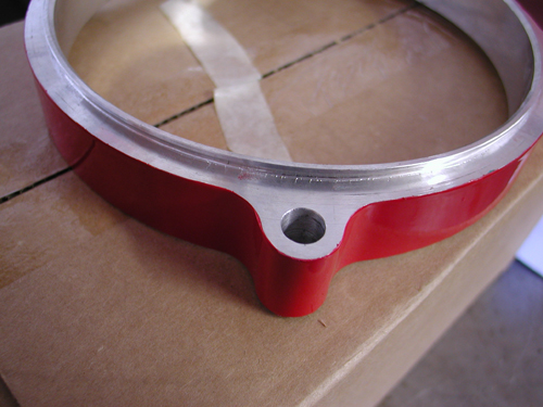
We used a bench polisher to clean the powdered edges on this inner-primary spacer.

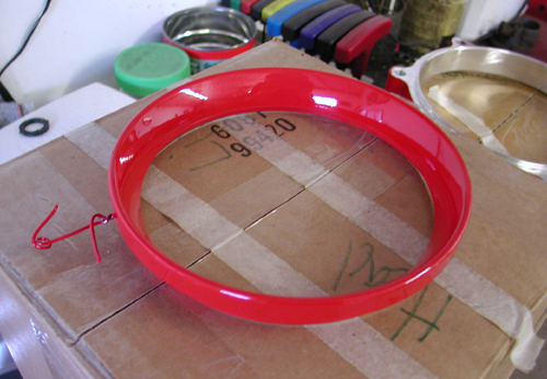
Here’s the red billet headlight ring.
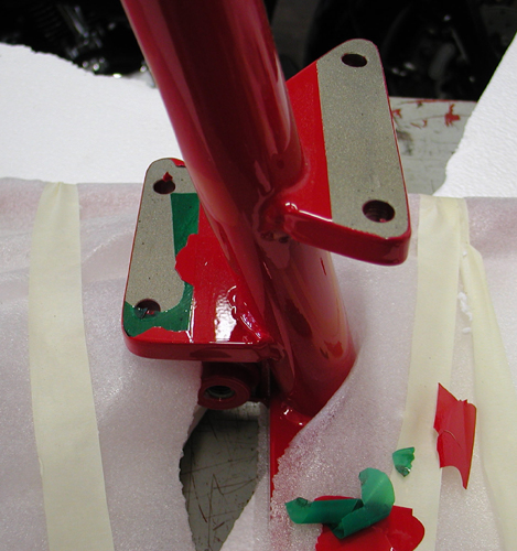
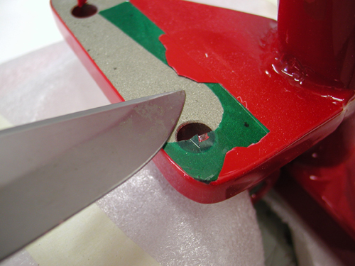
Scraping the tape free of the tranny mount for a solid bond.
Some of the frame threads needed chasing which eased assembly. Then Nuttboy bolted in the offset Tranny plate.
“The swingarm spacing was a turkey,” Nuttboy coughed trying to fit the axle. The swingarm axle came with several spacers, none fit perfectly, and we were forced to make spacers and set the swingarm up several times. He gave up on the swingarm and installed the shocks first then the tranny to make allowances for the studs. One had to be shaved due to the offset tranny plate.
Here’s some improved-shock instructions:
Place the motorcycle securely on a stand so no pressure is on the shocks.
Install the new shocks–the hardware was supplied
You’ll need a preload wrench from a dealership to adjust (94455-89).
The preload comes adjusted to the lightest setting. To increase the preload for heavier riders/loads/passengers, loosen the 11/16 locknut and back it off several turns. Use the 11/16 Harley adjustment wrench to turn the adjustment nut counterclockwise to the desired preload setting. Then tighten the 1-inch locknut. Both shocks must be adjusted to the same equal setting.
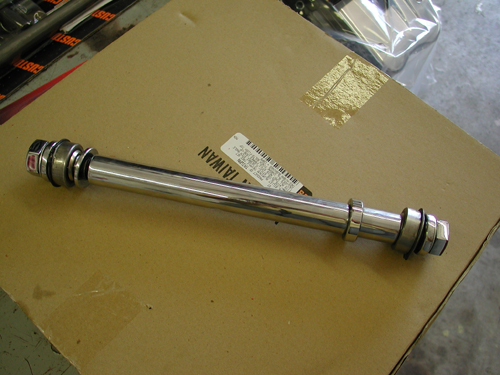
The swingarm axle came with a variety of spacers, but no guidance. The widened frame was almost two inches wider, maybe more. We would have loved a diagram.
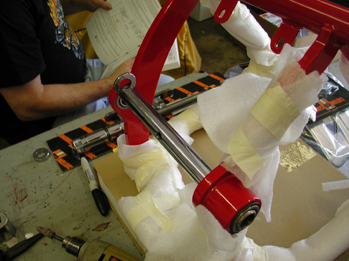
We grappled with it for a couple of hours, then took a research break. Part of the dilemma was the thick red powder coating on the inside of the frame and swingarm parts.
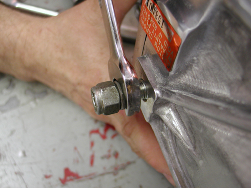
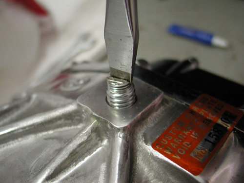
“The fifth stud was removed,” Nuttboy said, “there’s always a stud too many in the Bikernet garage,” Nuttboy commented. Another stud was shortened for clearance. He tightened the tranny plate down but not the tranny until the inner primary is aligned. Directions indicated an Allen plug to replace the 5th stud. We couldn’t find it, so shifted to plan B.
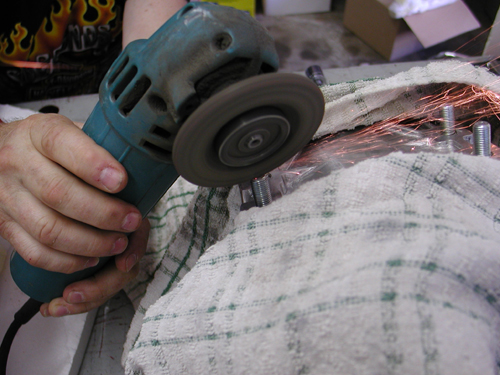
The rear right stud also was ground to clear the shocks due to the offset.
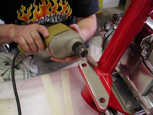
We slipped the engine in from the right. It fit perfectly although Nuttboy had to grind the left rear fin slot, to afford the clearance, for the mounting bolt to fit.
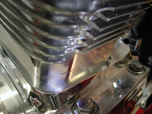
The massive barrels with additional cooling fin area had a slot pre-ground into the rear of the rear cylinder for the motormount bolt, but it wouldn’t fit unless we shaved the bolt or ground one more fin. We ground the fin.
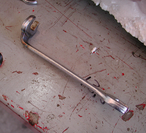
Here’s a 9/16 open end wrench that I bent, with torch heat, years ago to reach that bastard motormount nut behind the inner primary.
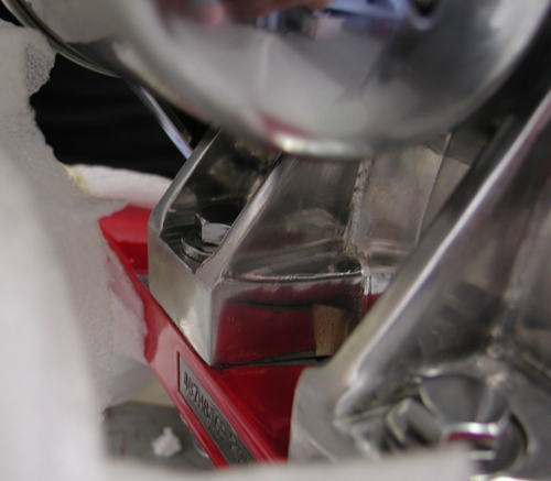
We mounted the front motormount bolts in loose at first. With the tranny and engine loose, we used the primary to align the driveline. This move is critical for alignment.
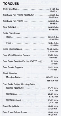
We slid on the inner primary, snugged it down and made sure the engine and the tranny aligned before tightening the motor and tranny mounts down. It’s best to tighten a few bolts, then remove the inner primary, and tighten the final bolts. Nuttboy referred to the stock Softail manual for torque specs (see torque chart at end of article). He made sure to install the rear belt before the swingarm and inner primary. “We still didn’t have the swingarm dialed in,” Nuttboy muttered turning wrenches. “The powder coating was thick and rubbery. This created an issue of tolerance and alignment. We often came to a ‘raise the bridge or lower the river’ type of decision. The swing arm installation gave us a clue, as to the need, to adapt. The instructions were either non-existent or cryptic. So we went with our mechanic’s intuition and marijuana paranoia.”
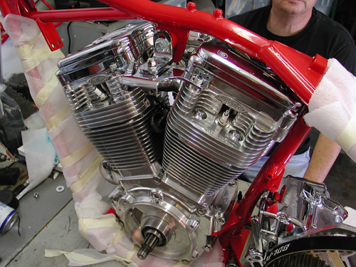
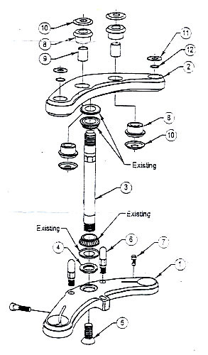
We also installed the front end on the first day. It was a breeze, except… Nuttboy followed the Remus book and kept in mind that the brake tabs run to the rear of the left leg. He dug through tin drawers to find rubber bumpers to slip over the fork stops and prevent the stops from dinging the frame. We decided to switch the bars for Custom Cycle Engineering, 8-inch, old school, dog bone risers and powder coated bars TT bars. “That will come later,” Nuttboy snapped tightening the lower tree pinch bolts.
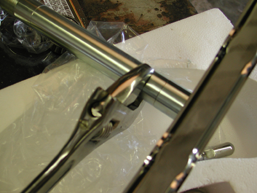
The stem was tightened to the lower triple-tree with a counter-sunk Allen on the bottom. We used the supplied red Loctite on anything that was assembled permanently.
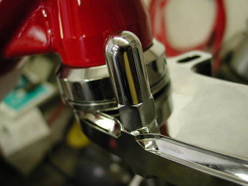
Here’s a fork stop in place. Easy livin’. We covered it with a rubber cap to minimize damage to the frame paint.
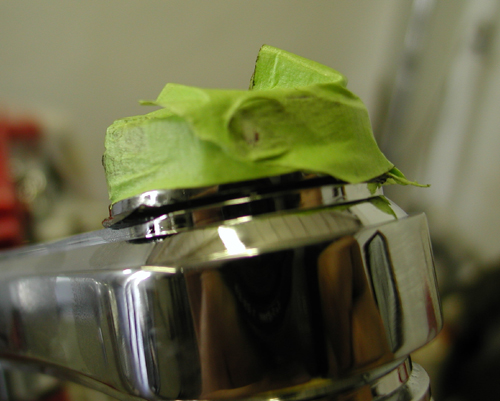
We used green masking tape around chromed fasteners to prevent peeling the plating. A rubber garden hose like washer goes in the top triple tree then a washer. For some reason these gaskets/oil seals loved to peel out or reacted to the fork tube fluid. We installed the caps loose initially, removed them and poured in 12.5 ounces of fork tube lube. Then we discovered that the assembled lower legs came with loose fasteners on the botton and loose drain plugs, so the fork fluid began to leak.
We replaced both fasteners with Tephlon tape for a secure seal.
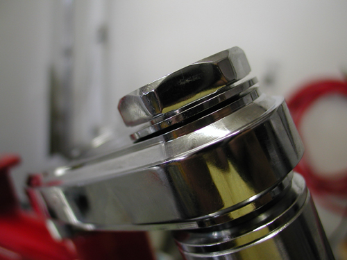
Nuttboy torqued the rotors to specs, 18-20 pounds for the front and 25 pounds for the rear and installed the clean billet caliper. The manual called 12.5 ounces of fork lube. That covered our first 6-hour day. The next day, the oil seeped out of one of the legs and was dripping out of the other. Nuttboy was pissed, “We had to re-seal the drain plugs with Teflon tape and tighten the Allens in the bottom of the legs after removing the front wheel.”

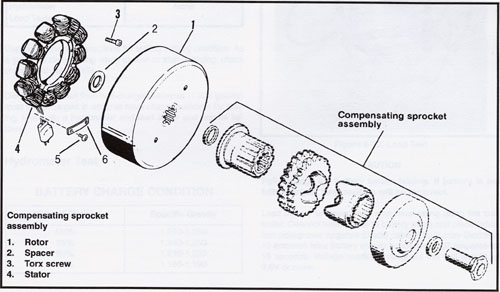
Day two began installing the primary drive. We slipped the stator in place with some light grease on the plug. Nuttboy was careful to face the stator so the plug wires ran comfortably inside the case. We greased the plug lightly so it would slide through the case easily. “Make sure to back out the Allen set screw or you’ll be screwed,” Nuttboy barked. “When replacing the screw, take it easy. It can bore right through the plug and cause a short.” He checked to make certain the regulator plug would connect properly before driving the set screw home.
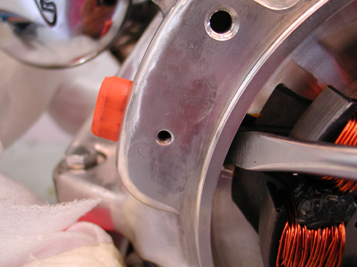
This is a delicate operation. If anything jams, stop and check it. Don’t force the plug, just guide it.
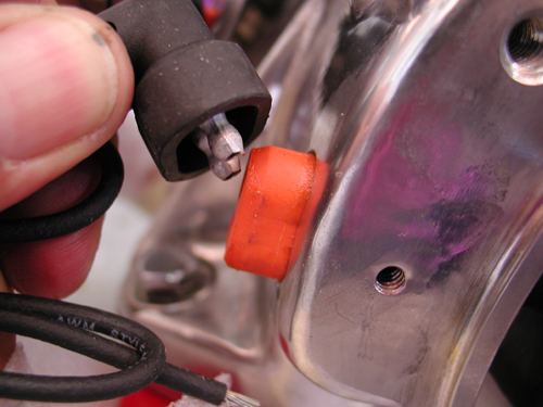
Once the plug protrudes, make sure it gives the regulator plug enough space to make a solid connection.
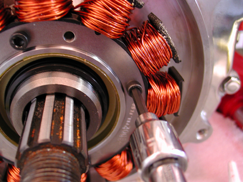
These little Torx fasteners come pre-Loctite coated. Tighten evenly to 30-40 inch pounds.
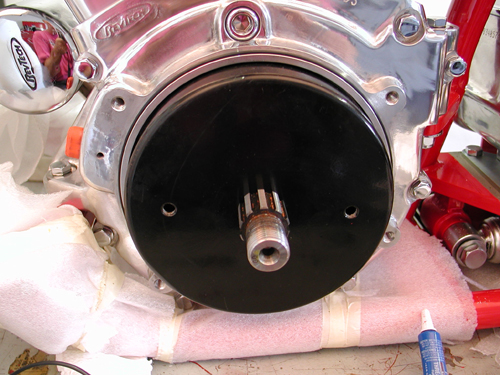
One spacer slips over the sprocket shaft before the rotor slides down the splines. It’s key to figure out which spacer is appropriate for the year you’re working with.
I compared several diagrams that run down the installation of rotor to make sure the proper washers were installed. The rotor slipped into place without a problem. “The kit came with a variety of shims to space the compensating sprocket properly with the clutch hub sprocket,” Nuttboy said.
“The Custom Chrome Goliath comes with virtually everything including fluids for the primary, forks, tranny and engine,” Nuttboy gagged, digging through reams of packing material. Once in awhile there was a quirk and the Tim Remus book helped. The chain adjuster parts included fasteners and extra parts, which was occasionally confusing.
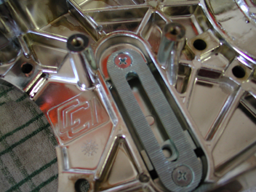
The chain adjuster came with several parts including a U-shaped bracket that would generally run on the back of the base plate. We installed the plate with red Loctite on the screws. Later we discovered that the plate had to be removed, because we should have found the proper chart and seen that it used a carriage bolt instead of the U-bracket. Our mistake.
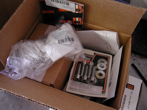
The Bikernet X-Files of fasteners.
“We had an ‘X-Files’ cardboard box for extra fasteners, unnecessary parts, and parts too damned weird to be from this planet,” Nuttboy pointed out clamoring through the box for a solution. “As we assembled the bike, the cardboard shipping boxes flew out the garage door, and the X-Files box overflowed.”
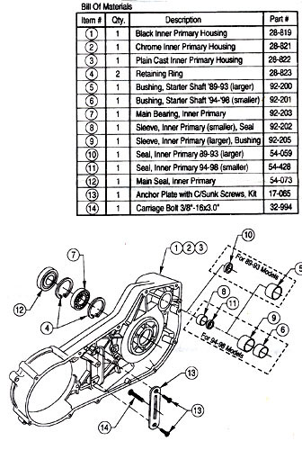
This diagram shows all the elements of the inner primary.
This brings up a key point in building a bike. Read everything first. If we had read Tim’s book from cover to cover, the manual and all the instructions, we would have saved some time. Keep in mind that we built this bike in nine days–part time. We were flying. That’s my goddamn excuse, and I’m sticking to it.
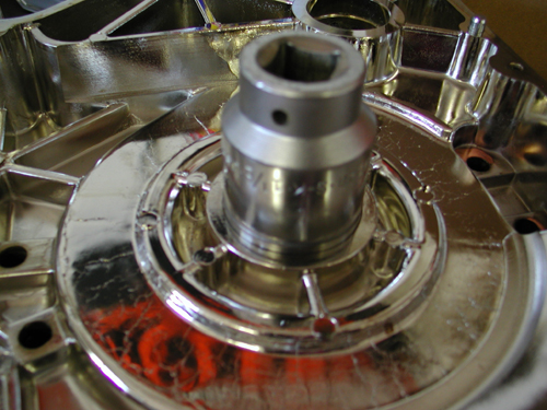
We handled the inner-primary bearing and seal at home with a brass hammer and just the right massive socket.
“This was an area where a pro shop came in handy,” Nuttboy commented trying to force the clutch together. Our garage was not equipped with a press. “Installing seals and bushings must be handled with care,” Nuttboy muttered after reading a comment in Tim’s book. Using a brass hammer and a large socket works, but is not recommended. “A good shop,” Nuttboy said loading the clutch parts in the truck, “like Larry Settle’s in Harbor City, California, can handle this aspect in five minutes.” With the bearing and seal in place, in the inner primary, and the proper bushing selected for the starter coupler, we were ready to install the inner primary and torqued the bolts to 20 pounds.
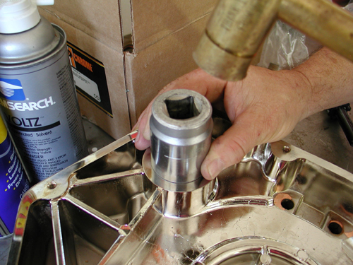
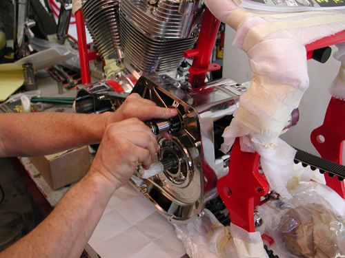
This bushing was also handled in the Bikernet Headquarters.
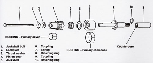
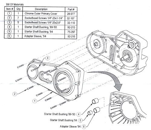
These are a bunch of tricky parts. Follow the diagram carefully.
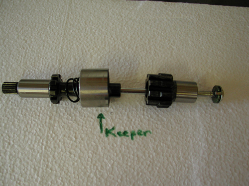
Here’s another shot of the starter shaft components. It’s easy, but make sure you have them in the correct order.

Should slip right in with some help between the inner primary and the tranny.
Picking the proper bushing was a key element. Since we didn’t have trememdous experience with various models we used the starter shaft parts as a guide.
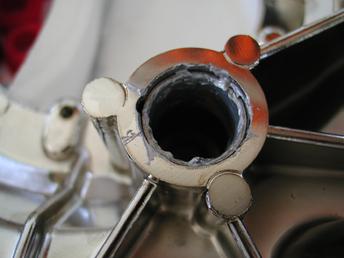
Here’s the outter primary bushing gooped with Never Cease.
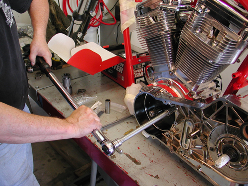
The inner primary was torqued into place. Don’t force it and make sure all the O-rings are in place around the engine spacer.

Here’s that goddamn chain adjuster in place.

Subscribe to American Rider, I did.
“Hold it,” Nuttboy barked from under the lift. “We inspected the edges of the powder coated wide drive spacer, first,” Nuttboy grumbled. “We greased the O-rings for a solid seal. The guys who worked with Tim on his book recommended Never-Cease instead of grease for primary related slippery parts.” The starter gears were a trick and we used the manual for guidance. Nuttboy installed the regulator after cleaning the installation area for a solid ground. He also installed the starter. That blew through another day, 8 hours.
Nuttboy ground off the regulator mount paint with the emery bit for a solid ground.
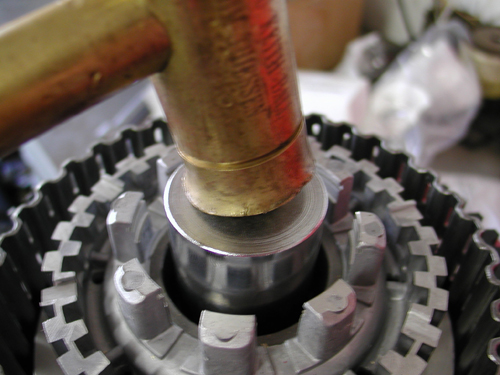
This was a bad and unsuccessful move. Larry Settles pressed the clutch together in five minutes at his shop. We need a press in the Headquarters.
We started the third day with the clutch hub and shell pressed together at Larry Settles’ and the fiber plates soaked in primary fluid over night. Nuttboy installed the clutch and compensating sprockets with the wide drive shaft extensions and shims. We tightened the Clutch hub nut to 70-80 foot pounds of torque and the compensating sprocket nut to 150-165 foot-pounds of torque. Then he checked the alignment of the primary chain and adjusted the shims behind the shaft extension to give us a .004 to .014 tolerance. After Nuttboy adjusted the clutch pushrod, it was time to bolt up the outer primary with a new gasket.
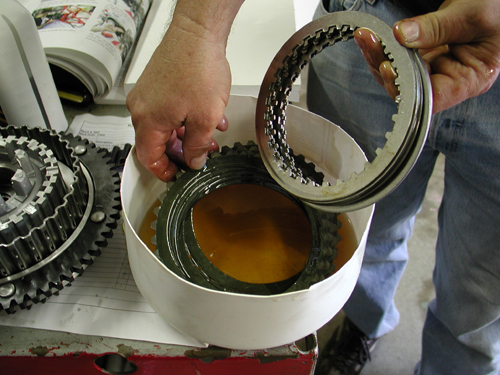
The fiber clutch plates were soaked for 24 hours in primary lube.
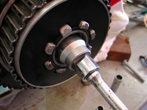
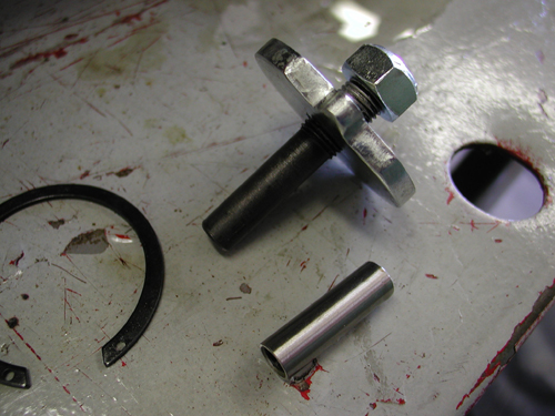
Here’s the pieces used with the clutch pushrod to adjust the clutch. Final pieces to be installed with clip ring pliers after the clutch is torqued into place.
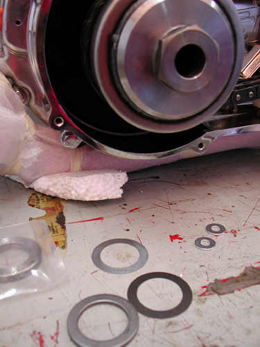
Here’s the compensating sprocket shims. After the clutch is installed and the sprocket with the chain we measured from the chain to edge of the inner primary with feeler gauges to make sure that the distance from the front of the chain to the clutch was no more than .014 inch. If not we needed to adjust the shims.
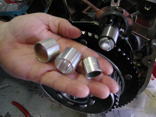
Here’s the various bushings out of focus.
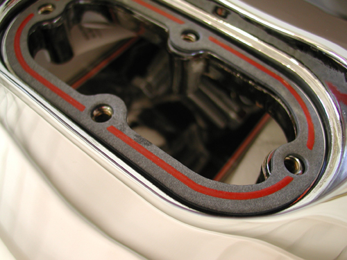
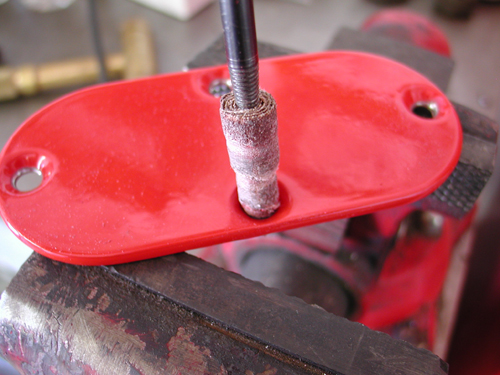
We cleaned up the countersunk holes for a tight fit.
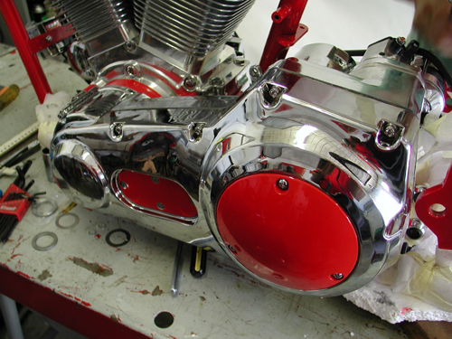
Ah, the primary locked-up. Don’t forget the fluid.
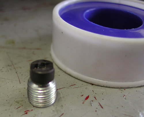
This is the primary drain plug with magnet attached and Tephlon tape in the background.
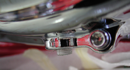
Primary plug in place. Later we were suspicious and pulled it, shaved off half of the magnet and replaced it. It may have been hitting the clutch.
“Ah, but first,” Nuttboy corrected, “we determined the correct bushing to press into the outer primary for the starter pinion gear. With primary installed Nuttboy bolted in the drain plug with Teflon tape and filled the inner primary to 1/4 inch above the clutch shell lip (with the bike upright) and attached the derby cover with an O-ring.
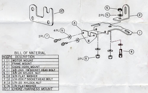
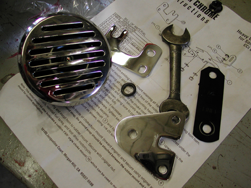
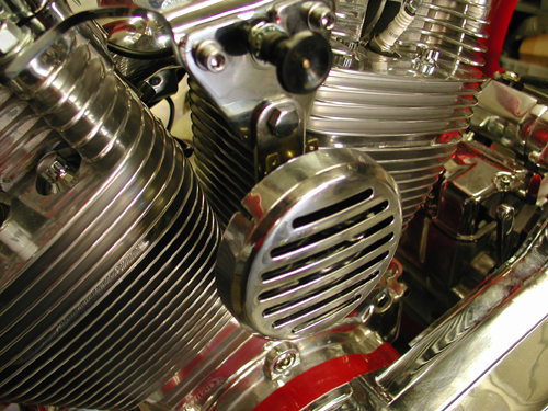
Here are the components involved with the top motormount. Keep in mind that the horn bracket is part of the mixture, unless you’re like me and would toss it in the trash.
Next we installed the top motor mount, horn and choke bracket. Watch this little puzzle closely. I ended up dropping the horn down some to make for more clearance.
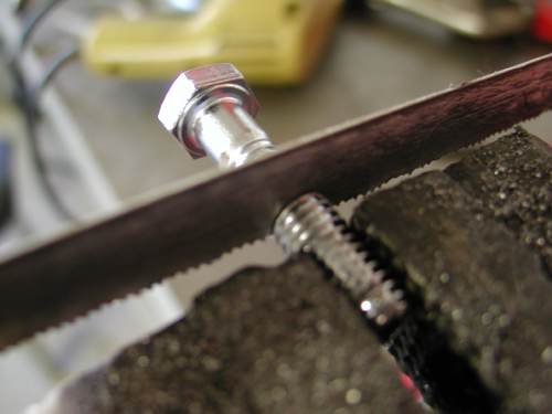
We trimmed a fastener to fit.
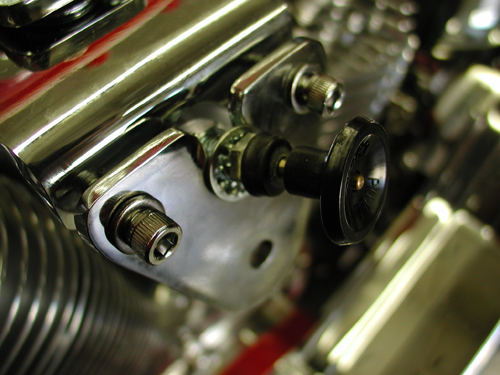
Ultimately we discovered that the gas tank touched the motormount bracket and had to move some spacers around.
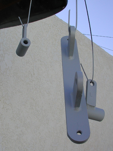
We found the oil tank brackets (unchromed) packaged with the rear axle. We primered them and painted them black.
Nuttboy then installed the battery cables. Tim’s book was helpful determining which cable went where. “It’s good to install them before you attempt the oil can assembly,” Nuttboy pointed out. The oil can brackets were vacuum packed with the rear axle and un-chromed. It was a hunt to find them.” Nuttboy spat. “Who would expect to find oil tank brackets packed with the rear axle?”
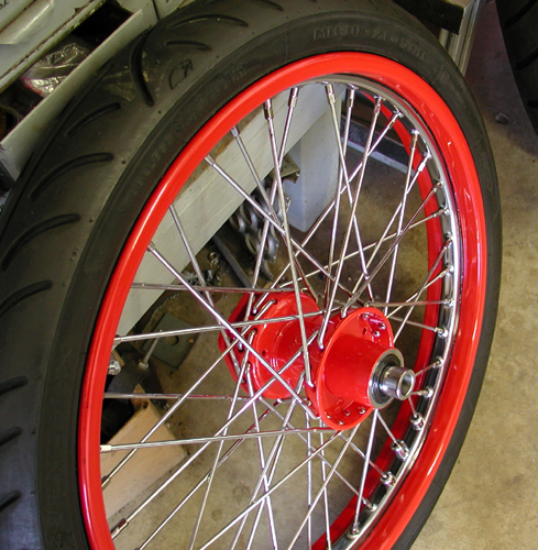
We moved onto the front wheel which had been powder coated and cleared by Custom Powder Coating, then George, The Wild Brush (310) 488-5488 pinstriped both wheels to conceal the powdered edge. The front wheel was a breeze using the one long spacer on the right and two short spacers for the left portion of the axle.
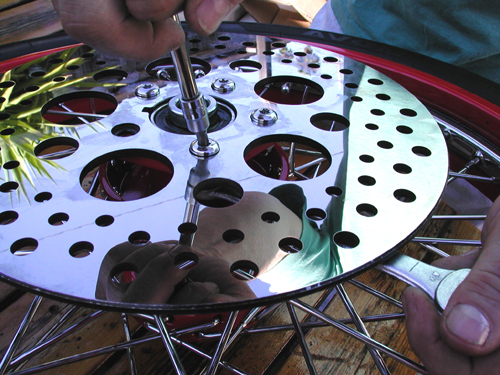
Make sure the wheel is centered and tightened down. Then with the supplied shims, center the caliper over the rotor.
“One had a small lip that fits in the seal and prevents it from falling out,” Nuttboy pointed out, his bike building, education expanding. Then we installed the caliper.
One of the most time-consuming aspects of building a bike is hunting and or making shims and spacers. Lotsa tools helps out.
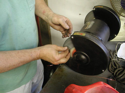
Nuttboy shaving a washer for a perfect fit.
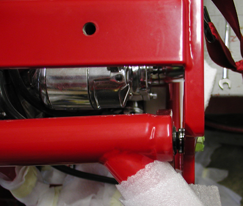
We sought to center the swingarm in the frame by manipulating spacers and shims.
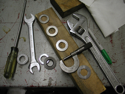
Here’s some of the tools involved in spacer/fitment wars.
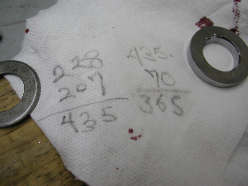
It took some precision calculations to fabricate the perfect fit.
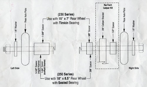
Finally we shifted back to the swingarm and spacing madness. Nuttboy worked the spacers until it was centered in the frame. “Where the shaft was a delicate problem,” Nuttboy grumbled, “the rear wheel was no problem.” He followed the supplied diagram to the tee, although one spacer had to be altered, perhaps due to the thickness of the protective powder coating.
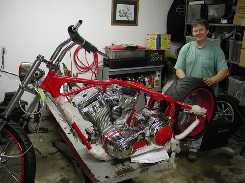
Sure we stumbled from time to time. We don’t build Softails daily, but the Beach Ride Bike was flying together. That summed up day three. Stay tuned as we stumble back into the teetering garage.
BRAND NEW CUSTOM CHROME CATALOG RELEASED–
Custom Chrome’s new offering for 2004. The California based distributor brings you the most comprehensive product offering in the Harley-Davidson aftermarket! At over 1,200 pages and over 22,000 part numbers, their 2004 Catalog features the new RevTech 110 Motor, Hard Core II, Ares bikekits and noumious frames and forks–everything from nuts & bolts to performance products. It’s the Custom Bike Bible for the year.
ONLY $9.95 + 6.95 Shipping**

Grab a beer, here’s part five of the Goliath Bike Build for the Exceptional Children’s Foundation Beach Ride. This promotional project wouldn’t be possible without the contribution and support of George Hayward, who funded it. The crew of Bikernet.com built the bike with additional hands belonging to a novice American Rider, Nuttboy. His past is too sordid to mention.

The frame, wheel rims, and miscellaneous parts were powder coated by Custom Powder Coating in Dallas (214) 638-6416 to match the hue used by Santini Paint (714) 891-8895, for the sheet metal.

As we wrapped up the third day of construction last issue we had installed the entire driveline front-end and both wheels. We were rocking with the assistance of the Tim Remus book, How To Build A Kit Bike. The book is available in the Bikernet Gulch. Let’s get to work.
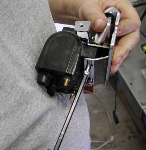
Nuttboy kicked off day four by installing the coil, which would seem a no-brainer. The bracket bolted to the frame stress tube behind the engine. The coil installed effortlessly, then the powder coated cover slipped into place. Unfortunately the cover fasteners didn’t line up.
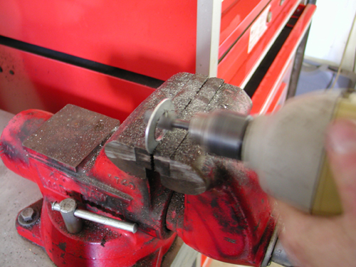
“Small buzzing tools and a careful hand corrected the problem,” Nuttboy muttered setting the dremel tool on the lift.
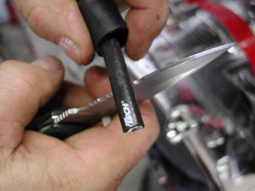
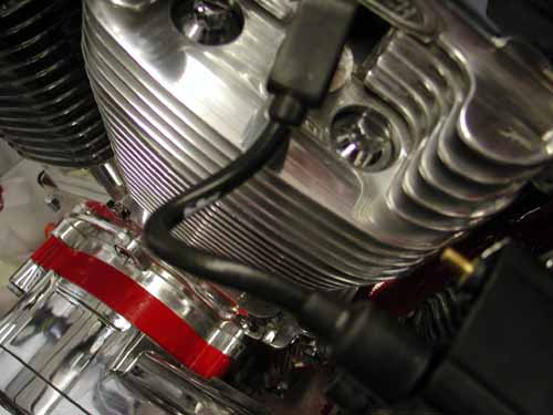
Setting up sparkplug wires isn’t rocket science. Measure them correctly, leaving plenty of slack for trimming. Make sure to pull the rubber boots on first so you don’t have to drag them over the brass fittings.
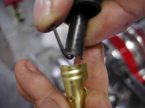
Also, trim plenty of insulation away from the carbon wire to make considerable contact when you bend the center over the end and press it between the insulation and the brass fitting. You don’t want it to vibrate loose and pop free to lose connection.
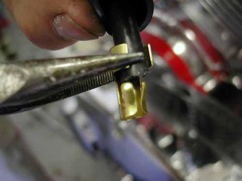
This takes finesse. Pinch them in from the sides then down in the center with needle nose pliers.
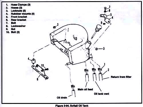
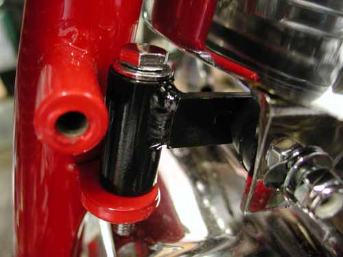
Nuttboy shifted to oil tank installation. The first aspect launched us into an interesting stumbling block. We couldn’t find the brackets for the oil tank? They weren’t with the oil tank at all. We dug through box after box. Here’s the key. If we ordered a complete Santee frame, it would be shipped with the oil tank and rear axle. Since we ordered the entire kit, the rear axle was vacuum wrapped separately from the frame and oil tank.
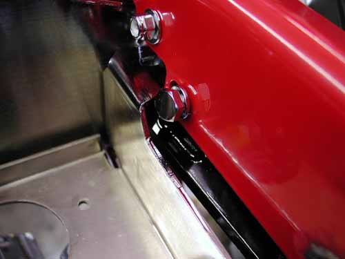
Guess what was plastic sealed with the rear axle? Yep, the two brackets for the front of the tank and the one long rear bracket. The oil tank is mounted front and rear with rubbermounted studs. Take it slow to figure out what goes where. Install everything loose first.
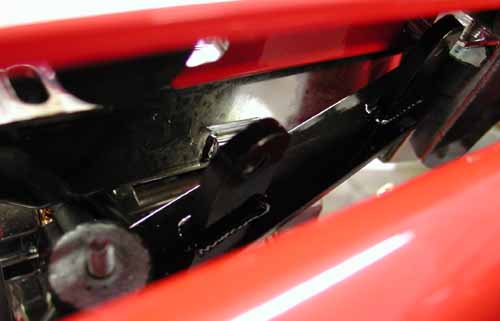
Since the mild steel brackets were missing in action we didn’t have them chromed or powder coated. That left the two-stage black rattle-can finish. We cleaned and primered them, then after 24 hours, hit them with a couple of coats of gloss black.
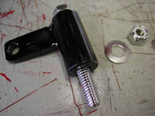
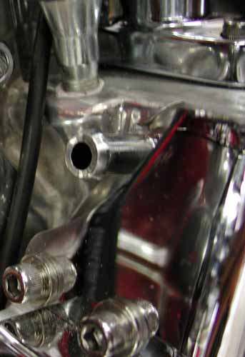
Here’s the case vent that runs directly to the inside front oil tank fitting.
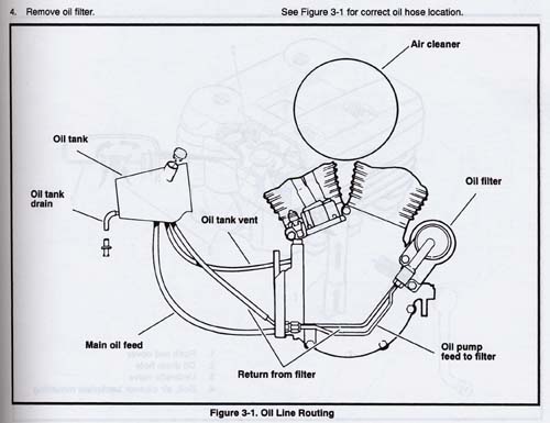
Nuttboy took care to run the vent line first, then the oil pump to filter hose following the diagram that comes with the RevTech 100-inch engine. He made absolutely sure to run lines carefully clear of sharp edges or hot parts. Next he installed the oil line from the filter to the tank.
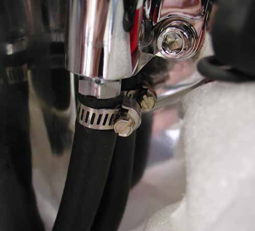
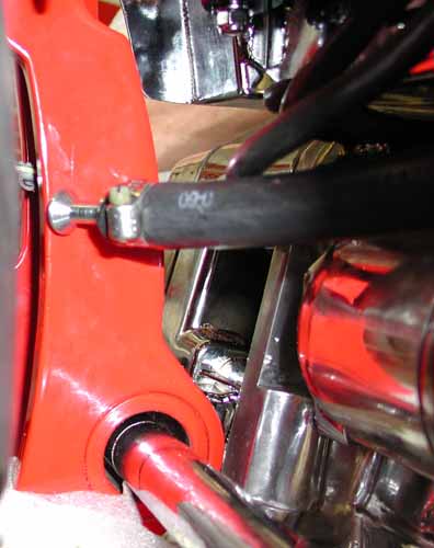
This line runs comfortable under the oil tank to allow draining clear to a funnel. You don’t want it to show, but make it as long as possible.
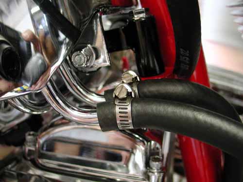
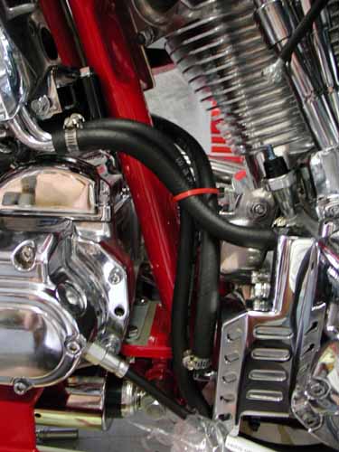
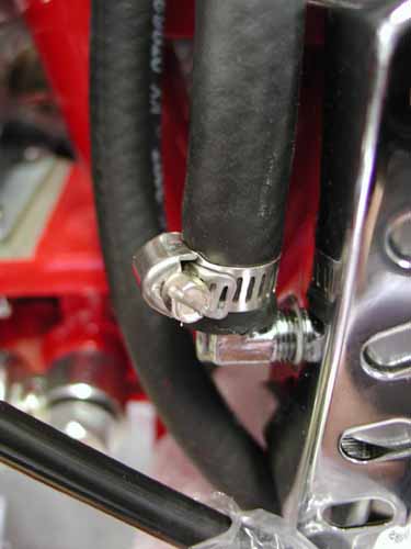
This one was a bastard to run.
Finally the feed line ran from the tank to the pump, “I don’t know why the it ran around the frame tube,” Nuttboy cussed, “It was a bitch to reach.” He noted that often it’s best to slip the hose clamps over the rubber tubes prior to sliding them over nipples. “Watch for the positioning of the clamp fasteners,” Nuttboy added, “It will save time and frustration.”
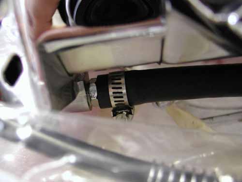
Here’s the return line from the oil pump to the oil filter.
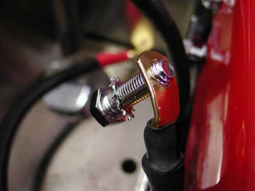
After the oil tank was installed Nuttboy decided to bolt up the ground strap. Here’s one of those reasons for never tightening something before you know it’s in the right spot. He installed a ground strap backward and we were forced to drill out the lug.
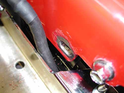
Next we picked a spot at the rear of the frame behind the oil tank to use as the ground. We cleaned away the heavy powder coating and sanded it to a bare frame before installing the cable. The cable runs from behind the starter to the frame and from behind the starter to the negative battery terminal for the best possible ground.

Next he dug through the parts box to find the forward foot controls. The right side connected easily to the frame with blue Loctite. The Left shift lever bracket and kickstand took a 1-inch spacer to make up for the offset primary, then we ran into a problem mounting the kickstand.
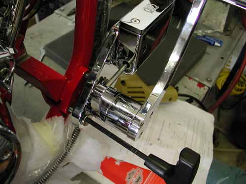
The right side bolted right up with Blue Loctite.
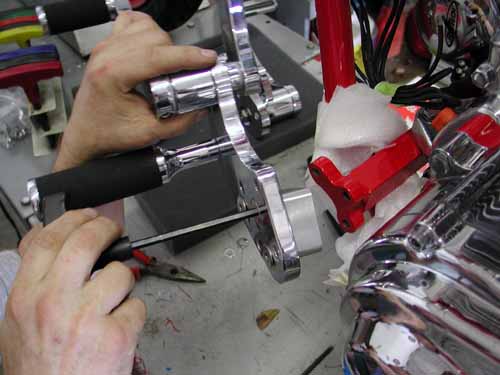
You can see the billet aluminum offset spacer to push the controls out an inch. We also needed longer bolts.
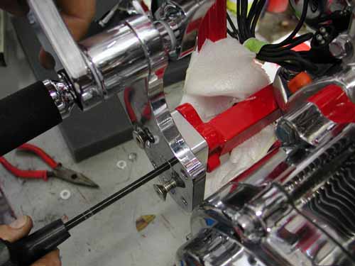
We used additional washers to solve a spacing hassle and moved ahead. All the fluids came with the kit, so Nuttboy quickly filled the oil tank. Another half day had slipped away.
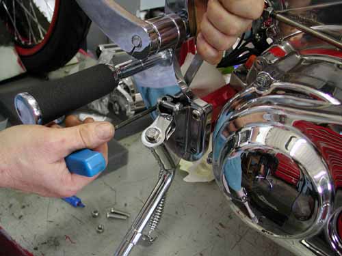
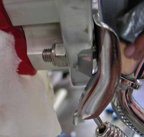
You can see where the kickstand bracket hit the backing plate for the shifter. Rather than grinding the plate we searched for some spacing washers to handle the job.

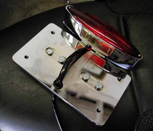
The Goliath kit comes with a massive Rick Doss, side mount, license plate and taillight bracket. We decided to use some aspects of it and tighten the look of the bike some. We drilled the bracket, dug around through drawers for the proper spacer and hardware and redesign the right footpeg mount to incorporate the license and taillight. It worked out tight and right.
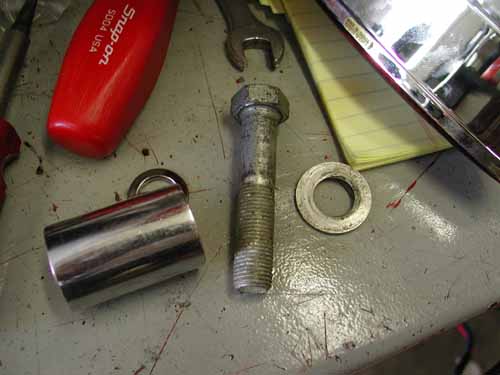
Here’s the spacer we found and the bolt.
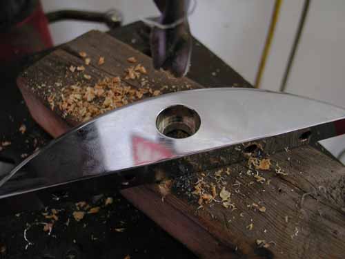
We drilled the bracket to 1/2-inch for the footpeg stud, ran the license vertical and were good to go.
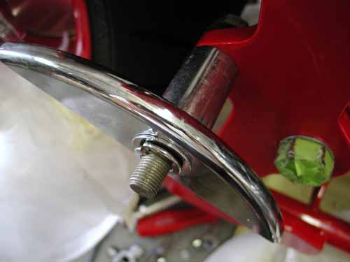
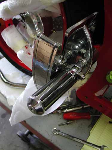
That’s it for this week. Stay tuned. We’ll try to drop in a Goliath tech every-other week until this puppy roars to life. If you’re interested in a bike build, order a Custom Chrome catalog first. It will give you tremendous info.
Stay Tuned.
–Bandit

BRAND NEW CUSTOM CHROME CATALOG RELEASED–
Custom Chrome’s new offering for 2004. The California based distributor brings you the most comprehensive product offering in the Harley-Davidson aftermarket! At over 1,200 pages and over 22,000 part numbers, their 2004 Catalog features the new RevTech 110 Motor, Hard Core II, Ares bikekits and countless frames and forks–everything from nuts & bolts to performance products. It’s the Custom Bike Bible for the year.
ONLY $9.95 + 6.95 Shipping**

Day five kicked off with a guessing-game tribute. It took us nine days to build this sonuvabitch and nine months to post the articles. No excuses, we’re getting there. We had to figure out which hydraulic lines and fittings went where. Nuttboy set up all the lines loose to test various configurations.
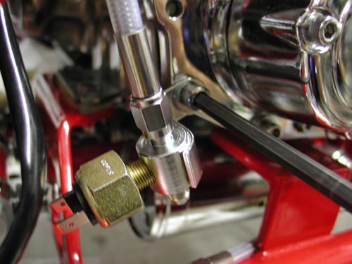
“Take some time,” Nuttboy muttered wondering if he had it right, “there’s no set rule.” There was just enough flexibility with the brake switch mounting to keep us guessing. Three puzzling lines were involved: Front brake, rear caliper to brake switch and brake switch to master cylinder.
Before locking down any lines we decided to adjust the shocks. They can only be properly calibrated with the bike jacked up to relieve any pressure. Then the eyes were released from the swingarm and spun. They don’t adjust from the center.
We set the bike low for looks, and for fender installation clearance. If we had set the bike high, mounted the fender then lowered it, we might have encountered fender rubbing problems. Ultimately we experienced the swingarm smacking the frame rails. I did some research and discovered other experienced builders with similar maladies. We spaced the rubber stoppers out to prevent further problems.
The hydraulic lines were notoriously long, but better long than short. With some creative ability we altered the position of the brake switch to make up for extra line length. Nuttboy Teflon coated fittings without copper or soft O-ring gaskets and tightened them appropriately.
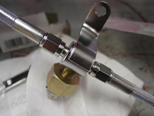
The front brake line was a breeze due to the assortment of fittings and one accurately measured line. The simple Rick Doss bracket with directions installed effortlessly under the bottom triple-tree for a custom touch.
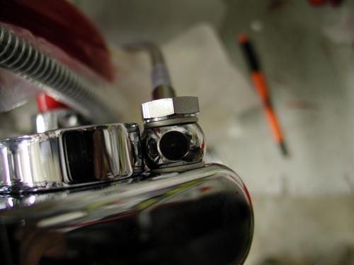
Next Nuttboy installed the speedo sensor in the trans. We searched for a 1/4-inch longer 1/4-20 Allen for the cap and 6-speed spacer. Since one didn’t come with the kit, we used a stainless Allen bolt that we polished for a chromed look.
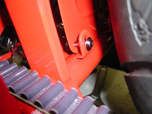
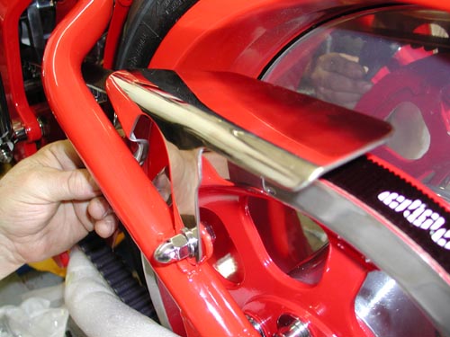
Nuttboy installed the powder coated rear splashguard with CCI supplied chromed fasteners. Since it wasn’t chromed we went with powder-red for a matched look. “Keep in mind,” Nuttboy spoke up after his second beer, “the splashguard goes on inside of the swingarm tabs, not the side closest to the tire.” We burned through another four hours and ducked out of the Bikernet headquarters.

BRAND NEW CUSTOM CHROME CATALOG RELEASED–
Custom Chrome’s new offering for 2004. The California based distributor brings you the most comprehensive product offering in the Harley-Davidson aftermarket! At over 1,200 pages and over 22,000 part numbers, their 2004 Catalog features the new RevTech 110 Motor, Hard Core II, Ares bikekits and noumious frames and forks–everything from nuts & bolts to performance products. It’s the Custom Bike Bible for the year.
ONLY $9.95 + 6.95 Shipping**

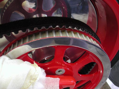
Day six, we checked our seven-day deadline. We had one day remaining. The powder coated pulley arrived from Texas with the edge polished and cleared. It was a nasty touch to the overall look of the bike. The Goliath came with a solid narrow pulley to match the massive rear wheel, but we decided on a change from H-D to add some detail. Not bad.

“I got in trouble,” Nuttboy muttered shuffling his boots on the deck, “I installed the pulley bolts in haste and dinged the swingarm paint above the axle with the ratchet extension.” By moving the wheel back, with the axle adjusters, clearance was enhanced. Nuttboy tightened the red Loctite touched fasteners to 55-65 foot pounds. The brake rotor was fastened with blue Loctite to 25-30 foot pounds of torque.
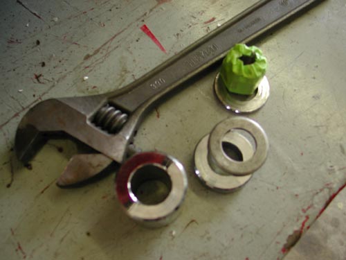
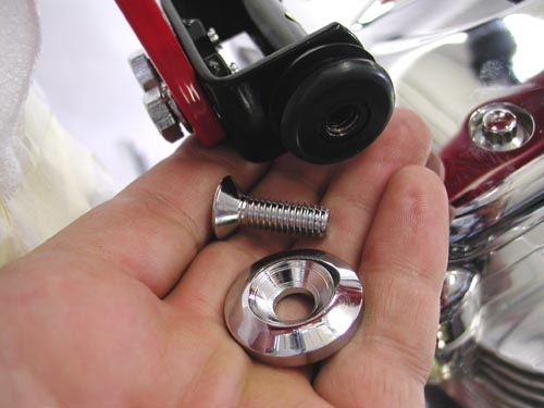
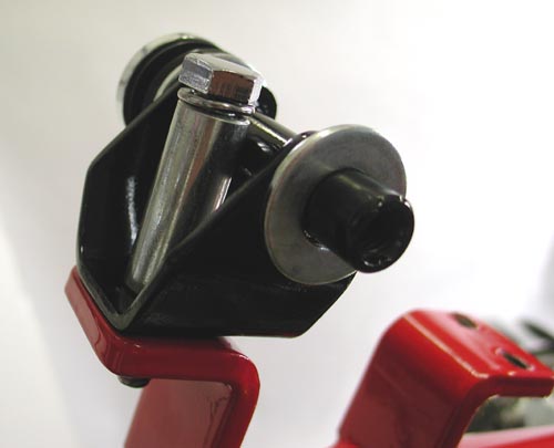
George delivered the sharp sheet metal from Santini Paint, and we quickly jumped the custom tank and suddenly noted that the top engine motor-mount position had to be adjusted for clearance. First off, we pried rubber grommets into the tank tabs using a wooden wedge to prevent damage to the paint or grommets.

Nuttboy installed the tank bracket and one side of the tank then chased the powder coated threads on the frame backbone. He installed the petcock considering the angle and position of the nipple and how the hose would route to the carb. Next he installed the gas line, the fuel filter, and the gas caps.
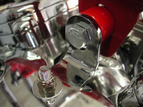
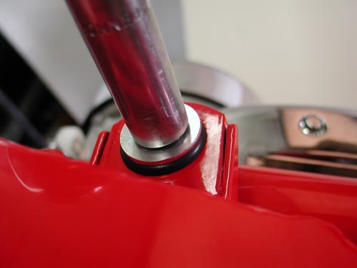
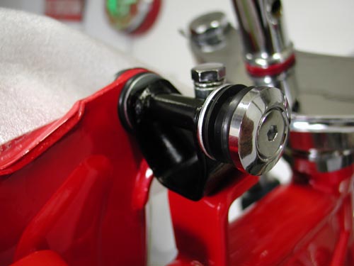
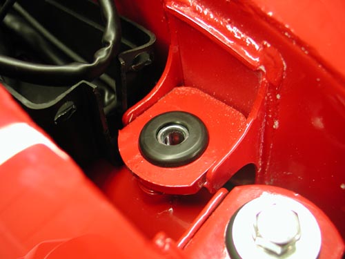
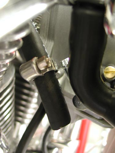
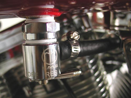
“Note,” Nuttboy interjected, “that the left gas cap has left-handed threads.” The bottom of the petcock was also left handed. “Don’t tighten them to the base,” Nuttboy added. “We centered the fittings in the threads. Then with Teflon coating the threads I screwed it into the tank bottom.” If the petcock wasn’t aimed properly we loosened the tank collar, aimed it and tightened it down. Another day slipped away.


Day Seven
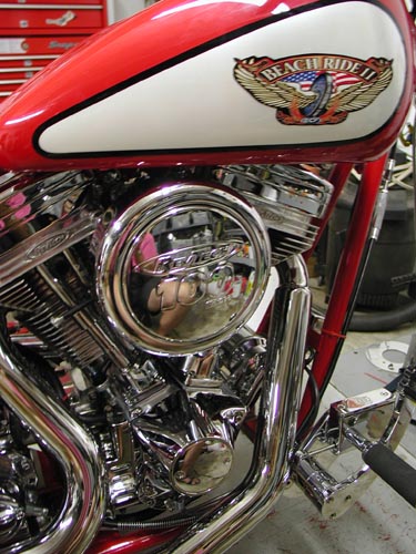
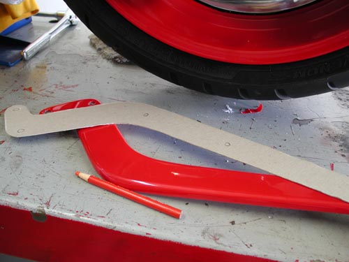
Day seven started with templates, our lovely female assistant, made of the fender rails and marked mounting holes. We installed the rails loose and masked them to prevent damage to the sheet metal. We created 1 1/4-inch spacers, taped them to the tire, made sure the wheel was aligned and removed the jack. We also adjusted the belt, so that the wheel was in running position. We chose 1 1/4 inches for the following reasons. The bike was lowered to the point that it had less than an inch of travel, maybe 3/4-inch. If it bottomed it still wouldn’t hit the fender by 1/2 inch. Keep in mind that there’s a seat bracket stud under the fender. Clearance was needed.
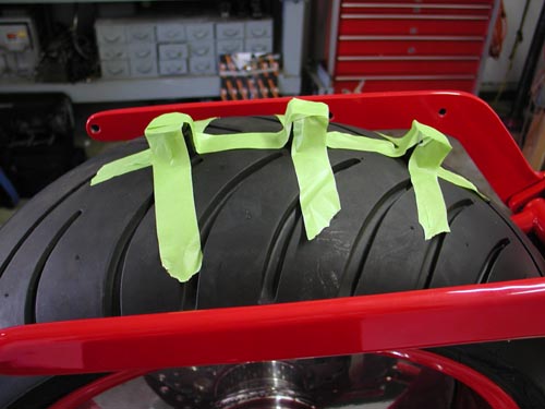
“This was a tough one,” Nuttboy said, “There wasn’t any specific fender mounting guidelines. We used the seat, styling looks and fender to tire spacers to indicate fender position.” I’m still not sure we did it correctly. Note the fender rail position, although it fit the seat perfectly.
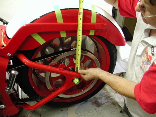
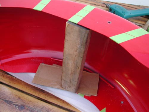
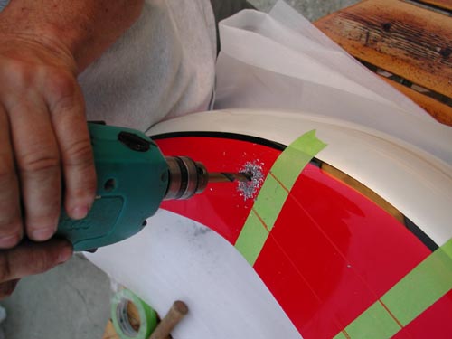
Using a grease pencil we marked the position of the fender rails on the fender, then the templates were used to note the position of the mounting holes. “First,” Nuttboy added with a bark, “drilling the mounting holes should take place before painting to prevent goof ball damage to the paint job.” He was right. Position the fender first, drill the holes and then paint the sucker. We had a screaming deadline an all the components rolled to powdercoating and paint before we could fuck with them. Ah, but George took the rails out to a machinist and had them radiused for a more refined look.
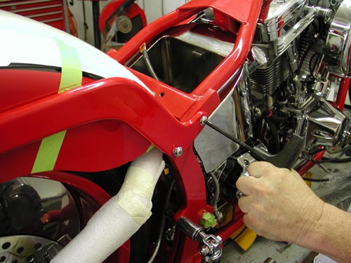
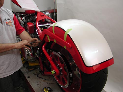
It’s helpful to drill the cardboard template and make sure that it is marked as exactly as possible. Then center-punch the fender and drill the first hole with a small bit. “Pray that the holes line up,” Nuttboy added. They didn’t and some monkey-business was necessary. That ended day seven.

BRAND NEW CUSTOM CHROME CATALOG RELEASED–
Custom Chrome’s new offering for 2004. The California based distributor brings you the most comprehensive product offering in the Harley-Davidson aftermarket! At over 1,200 pages and over 22,000 part numbers, their 2004 Catalog features the new RevTech 110 Motor, Hard Core II, Ares bikekits and noumious frames and forks–everything from nuts & bolts to performance products. It’s the Custom Bike Bible for the year.
ONLY $9.95 + 6.95 Shipping**
Day Eight

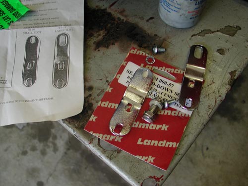
Day eight started at 11:30 a.m. when Nuttboy drilled the seat bracket hole, being careful not to drill through the tire. “Care must be taken mounting the seat grommet,” Nuttboy added. “There was a good 3/16-inch of bondo on the top of the fender.”
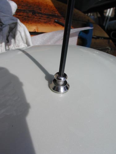
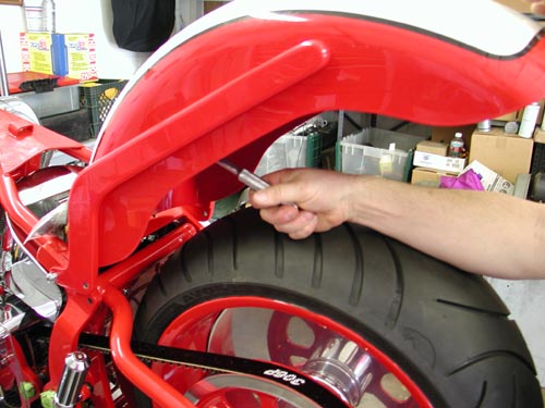
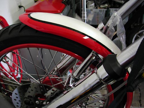
We were rockin’. We cleaned the fender holes, installed the bolts to the rails, loose and installed the fender on the frame with the rails attached, checked the fender location, tightened the rear fender bolts then rocked the fender, attached to the fender rails, forward and tightened the remaining bolts. Finally Nuttboy tightened the Allens holding the rails against the frame.
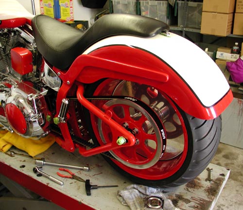
We moved right onto the powder coated handlebars and discovered that the throttle wouldn’t slip over the coating.
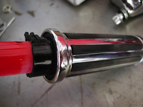
“Sanding was required,” Nuttboy explained. We didn’t use the pullback bars that came with the kit and replaced them with TT-bars and 8-inch Custom Cycle Engineering traditional dogbone risers.
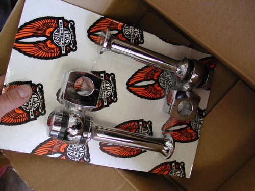
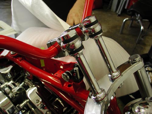
The bars, controls, switches, clutch and throttle cables are a bear. “Take your time,” Nuttboy muttered remembering the process. “I could have used four midget hands easily.” The right side is more complex because it encased throttle cables and throttle tension adjustment fasteners.
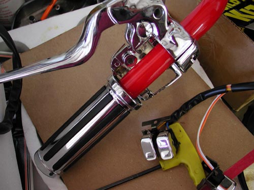
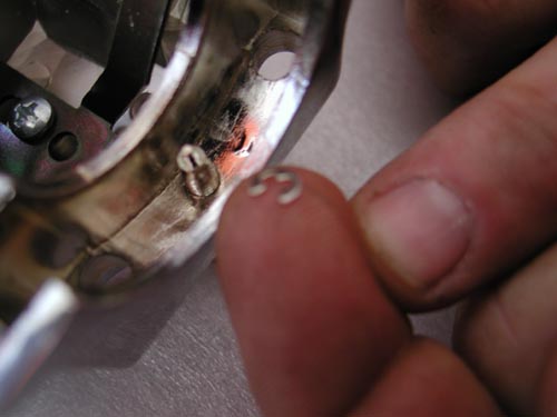
The tension screw was slipped into the base then Nuttboy struggled to fit a very tiny C-clip onto the shaft, so the adjuster could never vibrate out.
“Lube the cables before installation with a thin oil or silicone lubricant,” Nuttboy muttered. The throttle cables have two different diameter housings so you can’t go wrong. The cable with the spring on the end is the return cable. Make sure the throttle cables are routed cleanly, no binding.
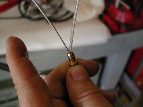
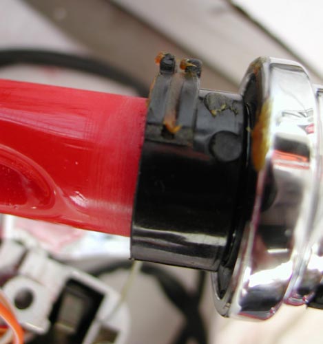
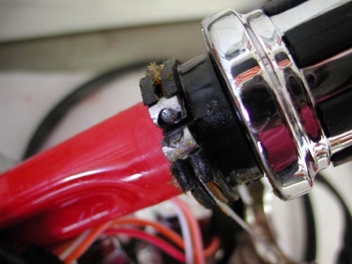
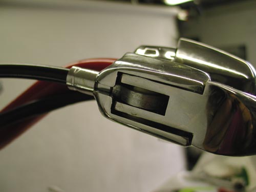
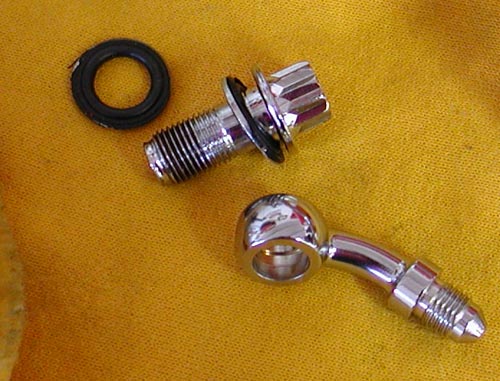
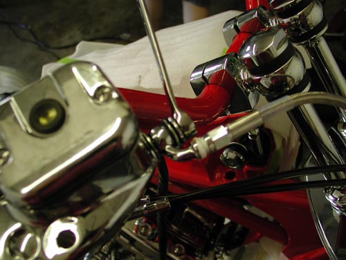
We were into our eighth day when we used the gravity method of bleeding the front brakes. We filled the master cylinder, pumped carefully and allowed the air bubbles to escape through the reservoir.
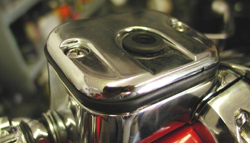
While it did its thing, we turned to the wiring. We’ll get to final aspects of the Goliath masterpiece in the next couple of weeks. Hold us to it. If you don’t see the wiring tech posted send me an e-mail. We need to wrap it up and go for a ride.
That’s is for this week. See you next time.
–Bandit


Okay, we’re late launching this, like by several months. I apologize and I’ve wired another bike between this bastard and now, so my memory fades. This predominately, took place on the ninth day of the build. Hell, we built the bike faster than we wrote or launched the articles–go figure. I prefer to wire bikes with few bullshit, little switches and gadgets that could leave me alongside the road. This called for nearly stock Softail wiring, although we did ditch the turn signals. The absolute keys to wiring are care, patience and a sketched out plan.
Draw a pencil sketch of the bike and where the components are positioned. The Thunder Heart wiring system came with three schematics. We had to figure out which one was appropriate for this scoot. Once we had it (Typical EHC Softail Wiring), nailed down wiring moved along .
“Yeah right,” Nuttboy spouted, “the headlight wires were not marked high or low beam, neither were the taillight wires or coil wires.” Some testing was required. The directions called for viewing the main circuit plugs from the mating end. “That wasn’t the case and we lost time, damaged the connectors, plus disassembling at the connector plugs is a bear,” he said and gulped his Corona. Fortunately we soldered each connection for a secure, lasting working fit.
The Thunder Heart consists of five major components. There are four harnesses: one for each side of the handlebars, one front harness, and one rear harness. There is also one central harness controller.
“They also pack in all the shrink-wrap, tie-wraps and connectors we needed,” Nuttboy added.
Each harness plugs into the central control unit. “We attached each wire to the terminal plugs,” Nuttboy said cringing. Individual wires are pushed through the backside of the plug. Then the connectors must be crimped into place and finally pushed into the plug base.
“We could go on about the wiring all night,” Nuttboy sniveled.

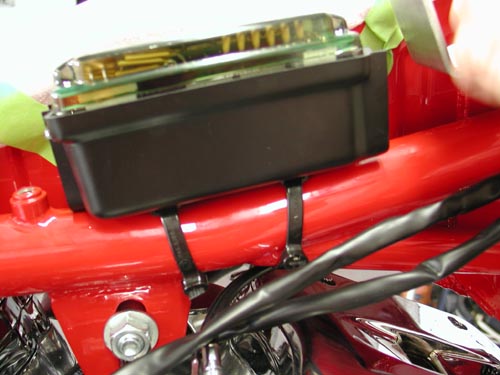
It’s true, but if you follow the code above and read the instruction, then take your time, you’ll be pleased with the outcome. The instructions call for mounting the Split Tank EHC control unit on the top frame tube between the gas tanks. The black plastic mounting base is molded to fit the tube radius and slotted to accept zip tie fasteners. The EHC latches onto the mounting base via the three mounting tabs so that the diagnostic instructions are visible with the dash removed.
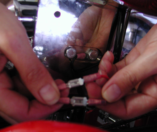
With the EHC mounted, attach the rear harness connector to the EHC mating connector. Notice that each wire is labeled according to its function. Route each wire to its destination, but do not cut to length just yet. Keep wires bundled together until they need to break off to their destination. Try to minimize the number of branches from the main harness by combining wires that branch off closely in one larger branch as they will make the heat shrink easier to apply later.
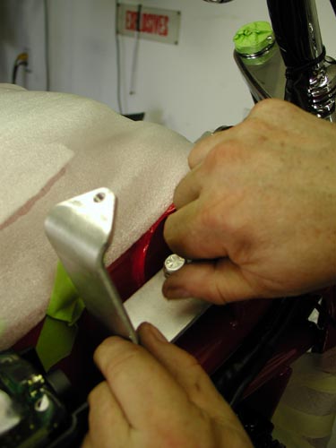
Use electrical tape to construct branch points and to temporarily attach harnesses while fitting is done. Remember to allow extra length for suspension movement or strain relief when locating attachment points. Take care to route harness away from sharp edges, surfaces that may pinch wires or hot pipes. Wires not used should be terminated at the connector to prevent short circuits. Repeat this procedure for the front harness and the right/left control harnesses. When all wires are routed and the harnesses are temporarily attached at their mounting points, cut the excess length from the ends of the wires leaving them approximately 3 inches too long for the final fitment.
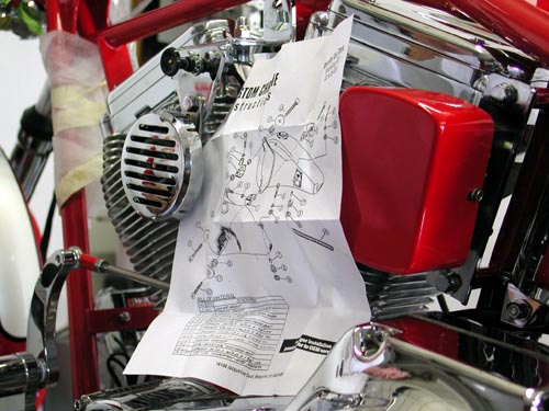
Note: the horn and aux power circuits are found on both front and rear harness connectors to allow for different mounting locations. Use the most convenient one for the horn, both aux power circuits may be used, or not, as needed.
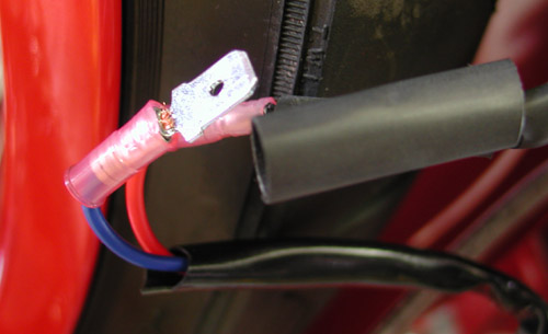
Once the harness has been trial fitted to the bike, remove it for the next step, which is to apply the heat shrinkable tubing. Starting from the main connector, cut a piece long enough so that it extends 1-inch past the first branch intersection. This extra length will allow the tubing for the branches to slide into the main tubing. This creates a smooth transition to the other legs of the harness. When a tubing section ends at a termination point (connector/terminal) slide a long piece into the main tubing and then cut at the end of the wire (taking off the last 1/4-inch or so of wire as well).

With the heat shrink tubing installed, use a heat gun to shrink the tubing starting at the main connector and working to the other end. Now refit the harness to the bike attaching the main connector to the EHC first, then attaching the harness to the frame where necessary. Finally, cut the ends of the harness to length allowing room for motion and strip the ends. Attach the terminals to the wire ends and use the heat gun to shrink the strain reliefs (if no shrink tube is attached to the terminal use the 1-inch pieces supplied in the kit.)
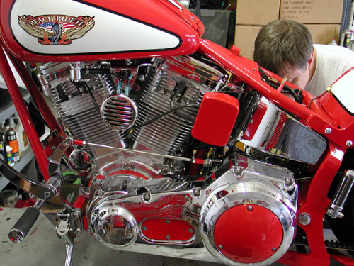
The EHC is designed to control LED type dash indicators. LEDs are brighter, vibration resistant, more power efficient, usually need no replacement and are generally easier to mount on a custom bike. When a Thunder Heart LED indicator panel is used, simply find a suitable mounting location and plug the supplied cable into the EHC.
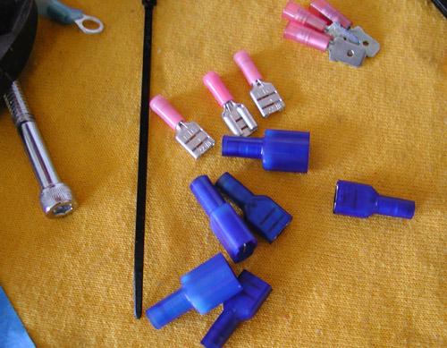
Day nine started with Bloody Marys at noon. We wired the speedo to the tranny using separate connectors from what the kit offered. We ground the instrument dash to the frame.
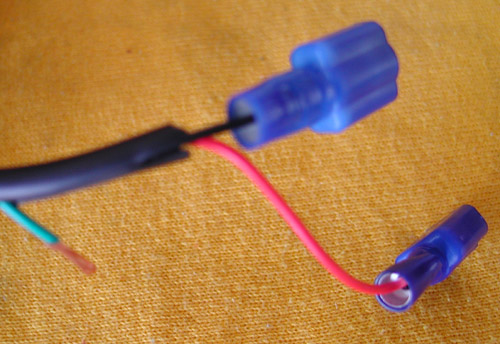
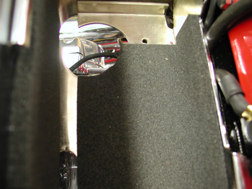
“This is all a trick of taking the time to route and combine the wires carefully,” Nuttboy added wringing his hands.

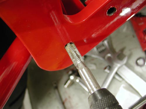
The dash was tricky to align for mounting and we fought it for a half hour. “We carefully drilled and taped the 1/4-20 hole in the frame,” Nuttboy pointed out, “to mount the rear of the dash.” We took a break to chase women then returned to the fray.
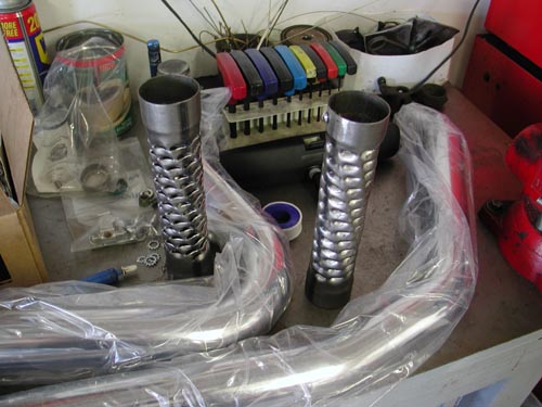
Next we cut the supplied Samson baffles in half to prevent over restricting the big straight pipes, then cut the pipes slightly to even the length and attached down-turned muffler tips.
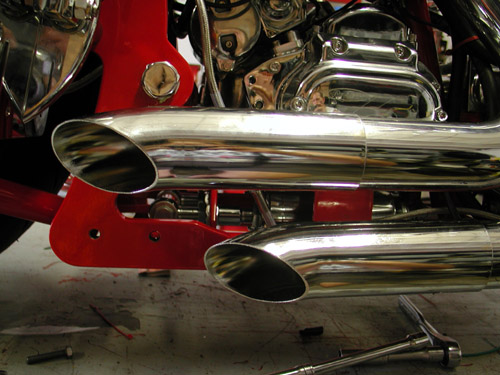
Actually San Pedro Muffler helped us with the modified exhaust, which we mounted to the right side transmission bracket for a clean, secure and light assembly.
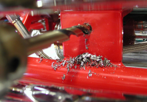
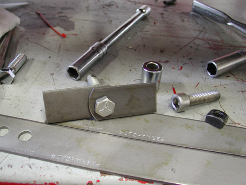

We couldn’t leave the pipes alone. They were 2-inch and bone straight. We added some baffle for performance back pressure downward tips for style and a respectable exhaust tone.
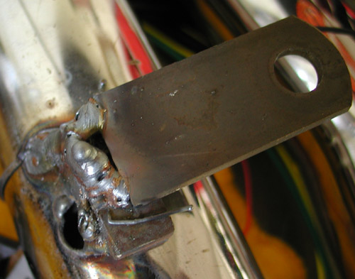
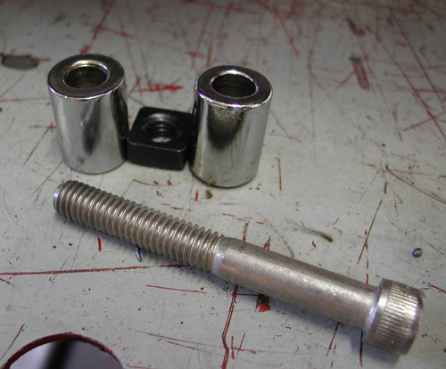
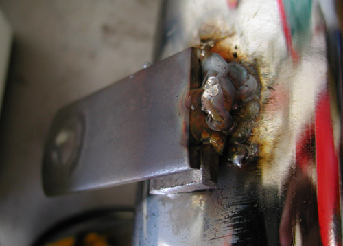
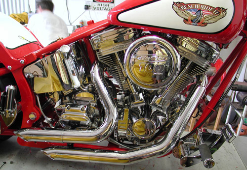
We also modified the Doss taillight (that is designed to run on the right side unlike most side-mounted lamps) and passenger peg for a tighter look. The tinkering and break-in period was upon us.
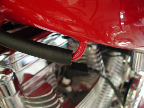
“Damn,” Nuttboy shouted from the garage. “We forgot the cross-over vent tube between the gas tanks. “
Watch out, when we reveal the finished product, the co-workers and the cheer-leading team of San Pedro alley punks. Don’t miss it. I swear, in the next couple of days.

BRAND NEW CUSTOM CHROME CATALOG RELEASED–
Want the Custom Chrome’s new offering for 2005. The California based distributor brings you the most comprehensive product offering in the Harley-Davidson aftermarket! At over 1,500 pages and over 25,000 part numbers, their 2005 Catalog features the new RevTech 110 Motor, Hard Core II, bikekits, frames and forks–everything from nuts & bolts to performance products. It’s the Custom Bike Bible for the year. No, this is not the latest book, just click on it to find the real deal.
ONLY $9.95 + 6.95 Shipping**
** Price may have changed.
Bandit 2006 Sturgis Shovel
By Robin Technologies |

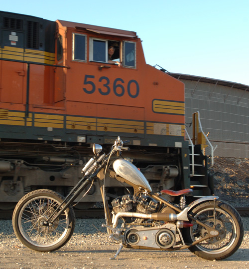
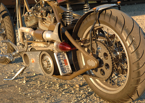
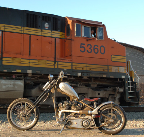
Editor's Note: You've seen the “American Iron” feature. Chris Maida, the editor, asked us to reshoot it, but we kept the original shots near the Wilmington, Califa, Port of Los Angeles rail road tracks. Just happened that a train rolled past in the middle of the shoot. Enjoy.–Bandit
I just did the Old School bit and rode this bike to Sturgis on our Bikernet.com 2005 run from the West Coast.
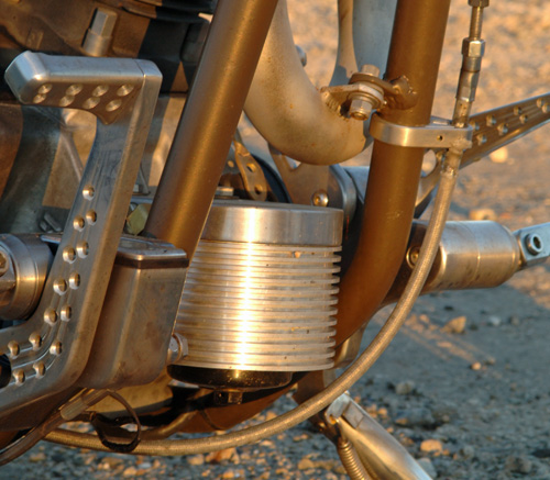
I cottoned to the pure machine marquee. I didn’t plan to paint it at all, unless absolutely necessary. I wanted to leave most components unblemished metals and incorporate as many iron types (for color) into the mix as possible. I wanted this mess to contain brass, copper, aluminum, steel, and stainless. Of course the steel corrosion dilemma dictated that we use some powder coating for a protective seal. The front end came in black to avoid chrome, so I supplemented the bike with a few additional black pieces, but the frame and some others were powdered to mimic a copper patina. Some aluminum parts were clear coated to prevent complete dulling and afford an acceptable pin striping surface. Some brushwork was applied.

It started with a Shovel engine that a brother gave me with a title. I loaned him a bike when he was down. Due to family illness he was forced to sell everything. There’s nothing better than an engine with a title. I took it from there and ordered a Paughco classic frame to fit me and handle like a midnight dream. Too many choppers today look good but don’t handle worth a damn. I wanted a bike to fit, handle well on freeways, yet be light in city traffic and parking lots. I spoke to Ron Paugh at Paughco and they built me a 4-inch up, 3-inch out, 35-degree raked rigid, wide enough to handle a 180 tire.
I don’t care for wide tire, fat-assed, beachball monsters. I decided to set my limit at 180 and run an O-ring chain for the traditional look. I stuck with a Paughco front end to top off the chassis. It’s one of their new tapered leg springers, 9-inches over with three degrees of rake in the trees. It worked out to be almost 5 inches of trail and handled as light as a dirt bike.
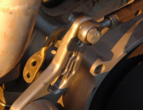
The engine had early stock heads, House of Horsepower cases and was a 105-inch stroker, too much for a rigid chassis. I wanted this bike to last, be a beater, but not be a dog. I contacted friends at S&S and they suggested 93 inches of street power for a balanced, reliable drive train. The stroke was reduced to 4.5 inch with 3 5/8 inch bore. The bike is fast but not a vibrating monster. I also spoke to Lee Chaffin at Mikuni and he suggested a 42mm, flat slide, Mikuni carb. “It will give you sharp throttle response,” he said. If I planned to run the Shovel on the salt flats he would have suggested a 45 mm venturi.
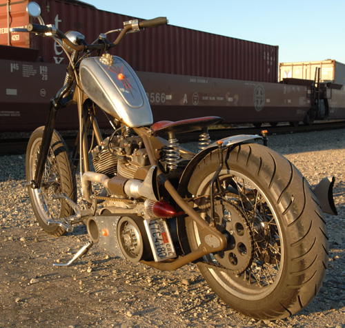
I have a couple of codes when it comes to building choppers. I like to keep them as simple as possible. On the other hand I like an oil cooler and filter to keep the drive train alive. I came across a system that bolted to the front motormount and doubled as a cooler while holding a spin-on filter (Rohm billet oil cooler mount). It was perfect. Other chopper codes include having enough taillight to prevent being run-over and enough gas to take you 100 miles before you hit reserve, or you’re looking for gas stations constantly. In this case I nearly broke the code a couple of times.
The Sportster gas tank originated on the verge of being beneath the acceptable fuel capacity, 1.75 gallons. It was an old Aluminum XR 750 race tank that we heavily modified. Get this: Some aluminum tanks are against the code, they’re too weak, notorious leakers. I broke the unwritten rule because it was a factory tank—cool right? Not so. “They broke during flat track races,” Berry Wardlaw, the Boss of Accurate Engineering, said at dinner in Deadwood, South Dakota, after I welded it twice on the way to Sturgis. “They ain’t worth the powder to blow ‘em to hell.”
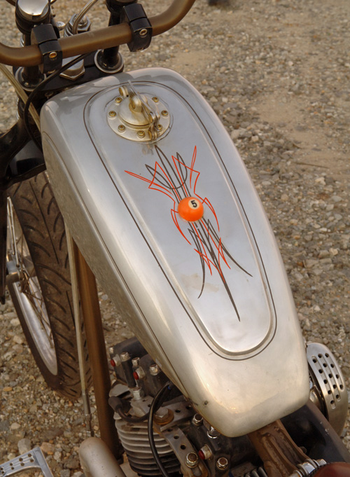
I put more work into that tank than the Martin Brothers pour into a set of one-off artistic sheet metal. First I added additional rubber mounted bungs to the base of the tank for added support, since I didn’t on the last Sturgis rigid. It broke twice. Because the tank would reside on a severe angle we moved the petcock to the rear, also for more fuel capacity. We drilled the tunnel and welded in a plate to allow the entire center section to augment petrol storage. Then I installed a Crime Scene speedster cap for an old school hot rod appearance.

Kent from lucky Devil Metal Works in Houston supported the aluminum theme by hand fabricating an aluminum fender to match the tank, front and rear. We scrapped the front job.
Back to the code. Remember the taillights, so a semi will at least recognize that it’s a motorcycle under his rip-roaring wheels. This is a tough one for me. I like the minimalist approach, but endeavor for some level of survival. The crew at Eye Candy Custom Cycles (.com) developed this hot looking, side-mount ’59 Cadillac taillight. I thought it was the cat’s paw and that I could mount it to glow through to both sides. I installed it to the BDL inner primary, so close and tight to the frame that no one could see it. I broke the code.
I also grappled with some elements of the wiring, but it worked out fine—that’s another story. I’ve been tinkering with bikes for 30 years, yet learned a tremendous amount with this build.
The bike continued to roll together like a dream with the Kraft Tech oil bag, hard copper oil lines, the Lucky Devil sprung seat and 5-speed Rev Tech Transmission. The wheels were Custom Chrome aluminum rims, stainless spokes and chromed steel hubs. This was the first time I ever used Brembo brakes, no problem and I’ve worked with Joker Machine controls for the last five years.
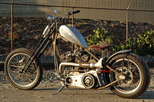
Let’s focus on mistakes I made, so you won’t make them in the future. The hard lines were cool, but I could have installed rubber hose and been finished in a half hour. Plus, since the Kraft Tech, round oil bag, was rubber mounted and the hard lines solid, the street vibration fucked with them and they cracked. I needed vibration resistant furrels. Let’s stick with the oil bag. It’s cool, solid and bolted right up, but battery choice is critical. There was very little space between the battery terminals and the frame. Ultimately, a Bikernet babe was called to the front, to stitch a rubber protective cushion to prevent shorts. That’s too close for everyday comfort.
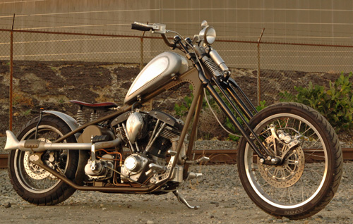
I broke in the bike using the Eddie Trotta formula for success, but missed one element, high-speed interstate travel. If I had put a few miles on the bike at 80 mph, which is against the break-in code, of 55 or less, I would have noticed the severe gearing. That’s where I went wrong. I started with a JIMS 6-speed and stock gearing. Then I discovered that the new Starter system from Compufire, that runs off the engine, wouldn’t be available for Sturgis, so I had to punt. I mounted the Dyna coils under the oil tank, which prevented a standard Compu-fire starter from being installed quick. A kicker was the answer. It fit with my hand made exhaust system using modified Samson mufflers, but I was forced to shift back to a Rev Tech 5-Speed transmission, because I needed the kicker. I should have considered a gear change at that point, but didn’t.

So what happened on the 1500-mile trek to the Badlands? The bike ran like a raped ape, strong and true. The handling was superb, everything remained in place except for the bullshit running lights I attempted to use for more visibility. They vibrated, spun, popped the bulbs and tore at the wires running through the fender rails. The ragged glitch in the road was the gearing. I ultimately replaced the running lights with these no-count reflectors and a H-D teardrop turnsignal under the right muffler.

The bike clocked 300 miles before I left town. Another 200 miles down the road toward Arizona, it had the mileage numbers to afford me enough break-in miles to drop the hammer and let her fly. At 90 mph I peeled past big rigs on Interstate10 heading out of the vast Los Angeles plague of concrete and stucco homes reaching dangerously close to the Arizona border. Crossing the state line, into the helmet-free state, I felt relieved to experience 100 degrees in the open desert flying toward Phoenix, another blight of concrete and southwestern architecture. I sensed the buzz in the frame and handlebar grips through Custom Cycle Engineering rubber mounted risers. The Shovel was over-revving and I needed that 6th gear release from extensive vibration, but I kept pushing for the love of speed, a light 520-pound, 93-inch chopper can deliver. She sliced the open road like a high-speed rotary knife through French bread.


I was beginning to buzz my feet off the Joker Machine pegs and adjusted them at the next stop. Rubber inserts on rigid pegs are mandatory, but I flaunted that rule with impunity. Just 60 miles out of Phoenix with the temps cresting 104 degrees and our group, of a half dozen, barreling along at over 90, the Sturgis Shovel quit, pure dead in the fast lane. I reached for the plug wires, then the ignition key that hovered less than a ½-inch from the whirling BDL belt drive. Better not go there, I thought as I signaled to lean right into the slow lane then onto the rough texture of the emergency lane where my baby came to a stop. That’s when I noticed the terrible, over-flowing gas leak at the back of the tank, all over the rear head.
As if the devil knew, one more mile and I would burst into flames in the middle of the searing desert. He flipped my ignition off. I never found an electrical problem or mechanical woe. She turned herself off because the vibration had taken its toll on the aluminum tank.

The next morning I was back on the road after Nick and Charlie at Custom Performance, (Turbo builders for Harleys, in Phoenix), had my tank rewelded and Nick recommended larger, softer rubber mounts. We were back on the road, where I took care of the beast for the rest of the run to Sturgis (kept my speed down), or until I could change the gearing. As it turned out, as I pulled into Deadwood, gas dripped onto that rear plug again. Bad news. There are codes and builders who know which ones can be broken—none. You can check the entire Sturgis Shovel Project build in our Bikernet Tech Department. The tank was repaired in Rapid City, but just two weeks ago I was forced to have it welded for the third time in Los Angeles. When will I learn?
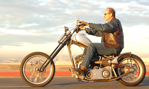
Ride Forever,
–Bandit
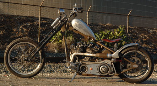
Owner: K. Randall “Bandit” Ball
Home: Wilmington, California
Builder: Bikernet.com
Year/model: 1956 Sturgis Shovel
Time to Build: 9 months
Color: Shit brown
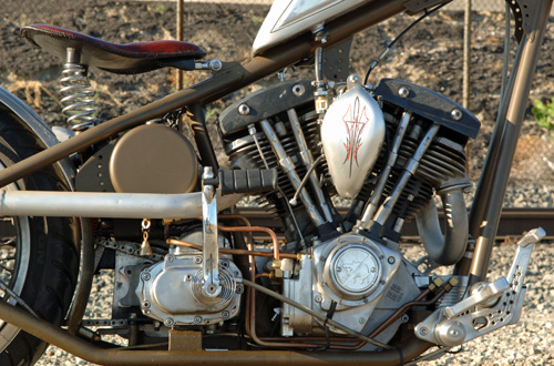
Engine/Transmission
Year/Model: 2005 S&S
Builder: Richard Kransler, Phil’s Speed Shop, and S&S
Displacement: 93 inches
Cases: House of Horsepower
Flywheels: S&S side-winder
Balancing: S&S, 1300 Bob weight
Connecting rods: S&S
Cylinders: S&S with longer skirts
Pistons: S&S forged, 8.2:1 compression
Heads: 1966 Shovelhead by Phil’s Speed
Cam: S&S
Valves: Black Diamond
Rockers: S&S rollers
Lifters: Custom Chrome
Pushrods: Custom Chrome
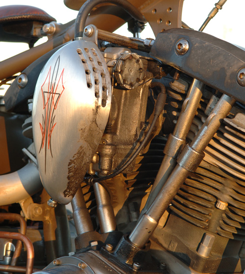
Carb: 42 mm Mikuni
Air Cleaner: Fantasy in Iron
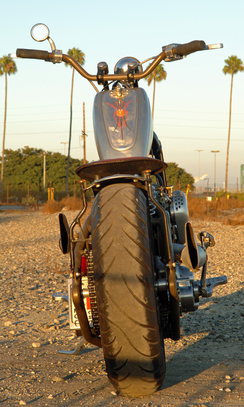
Exhaust: Bandit and Samson
Ignition: Compu-fire, single fire
Charging: Compu-fire
Oil Pump: S&S
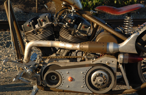
Transmission
Year/model: 2005 Rev Tech, 5-speed with kicker
Case: Rev Tech
Gears: Rev Tech
Clutch: BDL
Primary Drive: BDL open belt
Kick Starter: Rev Tech
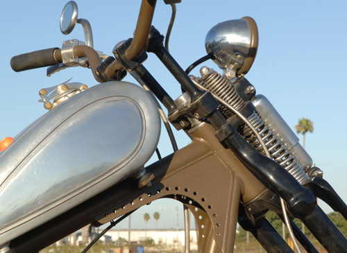
Chassis
Frame: Paughco Chopper
Rake: 35 degrees
Stretch: 3-out, 4-up
Front Forks: Paughco tapered-leg springer
Swingarm: none
Rear shocks: nope
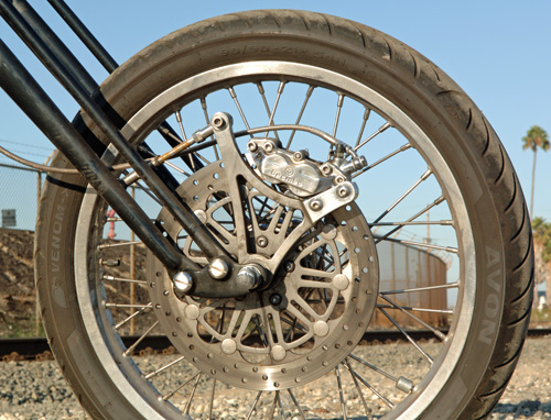
Front Wheel: 21-inch Custom Chrome
Rear Wheel: 18-inch Custom Chrome
Front Brake: Brembo Caliper and Springer Bracket
Rear Brake: Brembo Caliper and Softail Bracket
Front Tire: 21 Avon
Rear Tire: 18/180 Avon Venom
Rear Fender: Kent Weeks
Fender struts: Bandit
Headlight: Custom Chrome
Taillight: Eye Candy Custom Cycles
Fuel Tank: Aluminum 750 XR
Oil Tank: Kraft Tech
Handlebars: Custom Chrome narrowed
Risers: Custom Cycle Engineering dog bones
Seat: Lucky Devil Metal Works
License Bracket: Eye Candy Custom Cycles
Handlebar controls: Joker Machine
Foot Controls: Joker Machine


Witness Slips Needed Today
By Wayfarer |
|
|
Part 7 of VLXAFL5: Final Assembly Begins
By Wayfarer |
by Bandit with photos by Weed
The Paint Returned from TNT
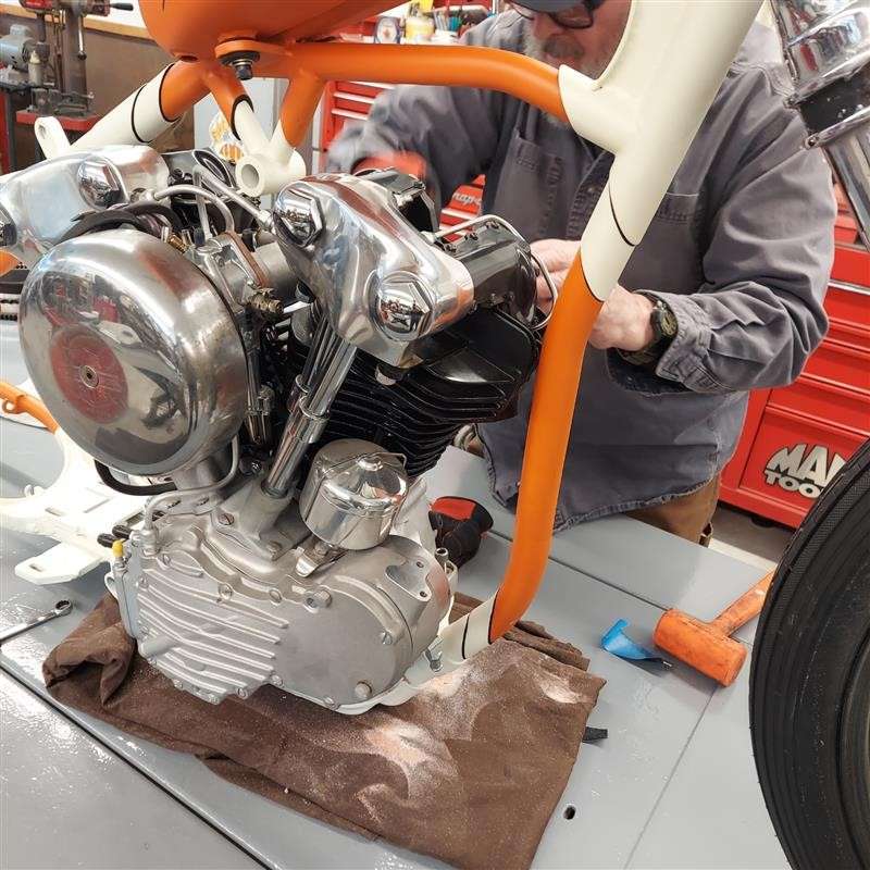
It’s been awhile, but I haven’t dawdled. I’ve been working hard on various projects. That guy in Deadwood, who was once 45 John bought a 1960 Panhead roller/basket case and I’ve been helping with the reconstruction. I rebuilt or built and trans from a case and a sketchy box of parts. With Fab Kevin we built a front disc brake. John rebuilt the rear star hub and I helped with fitment and the rear brake.
We slid in the engine after I stumbled. I used the rear axle and a flat lift jack to jack up the bike, so I could block it, remove the jack and start to install the 5-speed trans in a 4-speed S&S case. The trans didn’t want to go so I filed and ground all the paint out of the 4-speed slots and the slot I made and welded for the 5th stud on the right. I even had to grind the rear tab on the trans case more for additional clearance.
I couldn’t run an old school 4-speed trans for a couple of reasons. It’s an alternator S&S engine and I wanted it to be electric start.
Click here for the accelerating Tech adventure with detailed photos and tips.
* * * *
Don’t stop there, we have a whole department on Motorcycle Tech since 1996. Click and build now!
https://www.bikernet.com/pages/Techs_Bike_Builds.aspx
Harley-Davidson’s 2024 Factory King of the Baggers Team
By Wayfarer |

HARLEY-DAVIDSON FACTORY RACE TEAM LAUNCHES FOR 2024 MOTOAMERICA MISSON KING OF THE BAGGERS RACING SERIES
18-Race Schedule Includes Round at Red Bull Grand Prix of The Americas
MILWAUKEE (February 16, 2024) – The Harley-Davidson® Factory Race Team today launches its 2024 season with an exciting video featuring team riders Kyle Wyman and James Rispoli aboard new race-prepared 2024 Harley-Davidson® Road Glide® motorcycles based on the all-new touring platform for the MotoAmerica Mission King Of The Baggers road racing series. The video, with exclusive behind-the-scenes footage of the team, dials up the fun and irreverence of the King of the Baggers series, and will debut today on the Harley-Davidson YouTube Channel and other social channels.
An exciting special round was recently added to the 2024 Mission King Of The Baggers Championship by appearing during the third round of the FIM MotoGP World Championship at Circuit of The Americas in Austin, Texas, April 12-13. This two-race appearance during the Red Bull Grand Prix of The Americas weekend will mark the first time an international audience will see the thundering King Of The Baggers bikes in competition. In addition to the two points-paying races on Saturday, April 13, there will be a three-lap Mission Challenge on Friday afternoon with the six fastest qualifiers battling for a $5000 winner-take-all purse. This special round expands the 2024 Mission King Of The Baggers schedule to 18 total races.
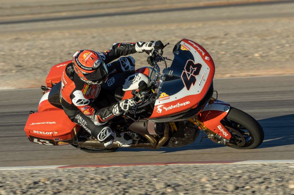
Wyman and Rispoli will compete aboard race-prepared 2024 Harley-Davidson Road Glide® motorcycles powered by modified Screamin’ Eagle® Milwaukee-Eight® 131 Performance Crate Engines. These motorcycles are based on the all-new 2024 Road Glide model, including the sleek new next-generation sharknose fairing design. Many of the race motorcycle body panels are formed with the same lightweight forged carbon fiber material featured on the 2024 CVO™ Road Glide® ST model. The team bikes also feature upgraded suspension components, including Screamin’ Eagle/Öhlins Remote Reservoir Rear Shocks, and competition Screamin’ Eagle exhaust, along with upgraded Brembo® Racing braking systems, Marchesini® wheels, and premium Harley-Davidson racing components produced by Protolabs®. The team motorcycles will appear in all-new livery featuring the classic Legendary Racing Orange color long associated with Harley-Davidson Factory Team racing bikes.
Wyman returns for a fourth season with the Harley-Davidson Factory Race Team. He won seven races during the 2023 King of the Baggers season and finished third in the season championship. Wyman is the most winning racer in MotoAmerica King of the Baggers history, with 12 total race wins in the 24 events since the start of the series in the 2021 season, plus the 2021 season championship to his credit. Wyman won the Daytona 200 in 2019.
Rispoli joins the team for the 2024 season after placing second in King of the Baggers series points in 2023 riding for the Vance & Hines Harley-Davidson team. In 2023, Rispoli won two races, and scored five second place finishes and three third place finishes. Rispoli began racing Harley-Davidson motorcycles as a teenager and earned the nickname “Hogspoli” after winning the 2020 American Flat Track Production Twins championship aboard a Latus Motors Racing Harley-Davidson XG750R. He also won back-to-back AMA Pro Racing Supersport championships in 2011-2012.
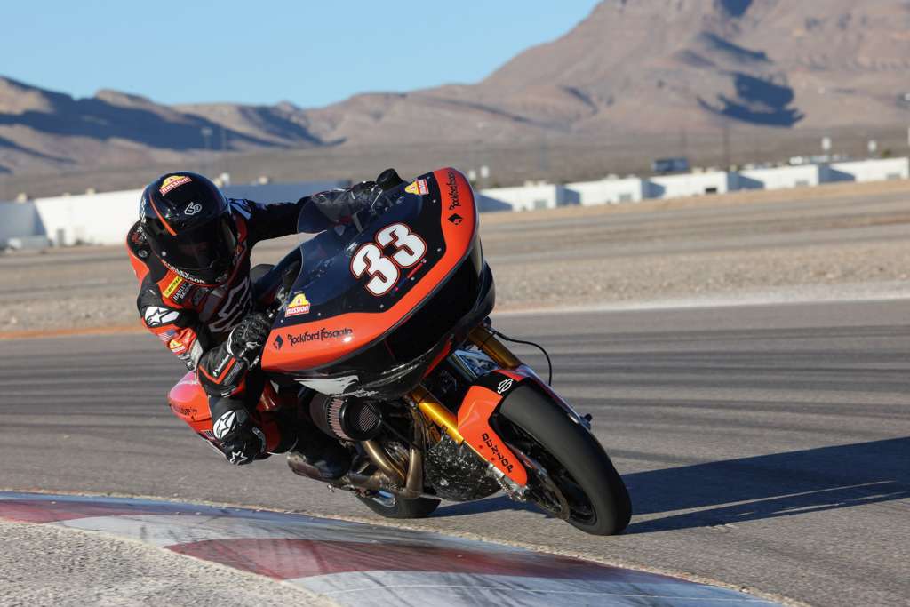
For the 2024 season, the Harley-Davidson® Factory Race Team is sponsored by Mission® Foods, Rockford Fosgate®, Brembo®, Öhlins®, Protolabs®, SYN3® lubricants, and Screamin’ Eagle® Performance Parts and Accessories.
The MotoAmerica King Of The Baggers series offers exciting competition between American V-Twin touring motorcycles prepared for competition and equipped with a fairing/windscreen and saddlebags. The 2024 series has expanded to 18 races over nine double-header weekends held in conjunction with the MotoAmerica Superbike Series. The series opens on the high banks of Daytona International Speedway in Daytona Beach, Florida, March 7-9. To experience all the King Of The Baggers action in 2024, check out the Harley-Davidson Factory Race Fan Ticket Packages.
2024 MotoAmerica Mission King Of The Baggers Season Schedule
(Two races each weekend)
March 7-9: Daytona International Raceway – Daytona Beach, Fla.
April 12-13: Circuit of The Americas – Austin, Texas (Red Bull Grand Prix of The Americas)
April 19-21: Michelin Raceway Road Atlanta – Braselton, Ga.
May 31-June 2: Road America – Elkhart Lake, Wis.
June 14-16: Brainerd International Raceway – Brainerd, Minn.
July 12-14: WeatherTech Raceway Laguna Seca – Monterey, Calif.
August 16-18: Mid-Ohio Sports Car Course – Lexington, Ohio
September 13-15: Circuit of the Americas – Austin, Texas
September 27-29: New Jersey Motorsports Park – Millville, N.J.
* * * *
FINAL DAY 30% PRES DAY SALE – ENDS TONIGHT
By Wayfarer |
President’s Day Weekend Sale. 30% Off Sitewide.
Starts today through 19-February 12 PM
CODE: PRES30NMC
www.nashmotorcycle.com
* * * *
House Motorcycle Caucus Leadership
By Wayfarer |
New Leadership For House Motorcycle Caucus
This week, the House Motorcycle Caucus announced changes to its leadership team. Congressman Michael Burgess of Texas, who will retire at the end of the year, has stepped down as co-chair of the caucus. Congressman Burgess helped found the caucus in 2009 and has been a tireless champion for bikers. He was the 2018 MRF Legislative Champion of the Year and we wish him well on his retirement!
The current co-chair, Congressman Tim Walberg of Michigan, revealed that Congressman Troy Balderson of Ohio and Congressman Donald Norcross of New Jersey will join him as the new co-chairs. Mr. Balderson and Mr. Norcross are longtime members of the House Motorcycle Caucus and strong supporters of biker priorities. The House Motorcycle Caucus has always been a bipartisan group, so we are pleased to see Representative Norcross, a Democrat, join two Republicans as a co-chair.
Additionally, the caucus named Freshman Congressman Derrick Van Orden of Wisconsin as vice chair. Mr. Van Orden is an avid motorcyclist who made a point to ride his motorcycle to the Capitol for his first day in office!
Thank you to all those who will lead and are members of the House Motorcycle Caucus. Remember, this organization and its sister group, the Senate Motorcycle Caucus, exist to educate, legislate and publicize the priorities of bikers on Capitol Hill.
Below is a current list of House Motorcycle Caucus members as of Thursday, February 15th, 2024.
Don Bacon (R-NE)
Troy Balderson (R-OH)
Jim Banks (R-IN)
Mike Bost (R-IL)
Angie Craig (D-MN)
Rick Crawford (R-AR)
John Curtis (R-UT)
Tom Emmer (R-MN)
Paul Gosar (R-AZ)
Glenn Grothman (R-WI)
Andy Harris (R-MD)
Dusty Johnson (R-SD)
Anne Kuster (D-NH)
Doug Lamborn (R-CO)
Tracy Mann (R-KS)
Mariannette Miller-Meeks (R-IA)
Donald Norcross (D-NJ)
Scott Perry (R-PA)
Bill Posey (R-FL)
Adam Smith (D-WA)
Pete Stauber (R-MN)
Bryan Steil (R-WI)
Chris Stewart (R-UT)
Glenn “GT” Thompson (R-PA)
Dina Titus (D-NV)
Derrick Van Orden (R-WI)
Michael Waltz (R-FL)
Joe Wilson (R-SC)
Ride With The Leaders ™ by joining the MRF at https://mrf.org/ or call (202) 546-0983
* * * *

