
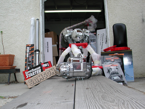
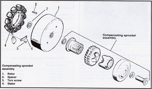
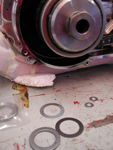
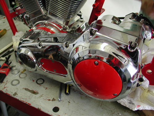
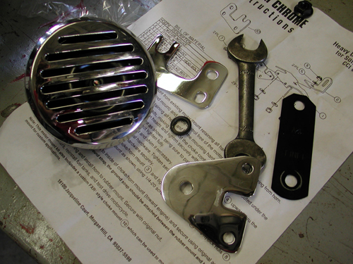
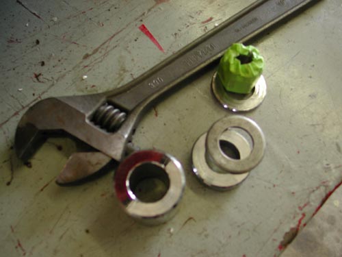
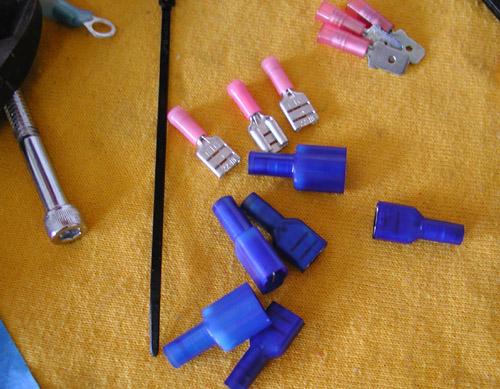
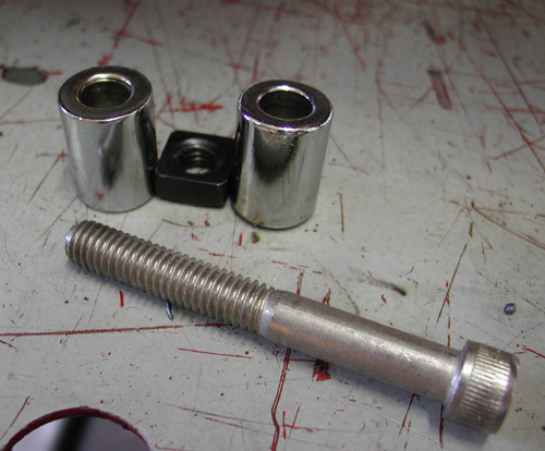
This shows just a fragment of all the parts involved.
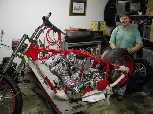
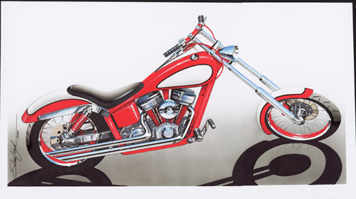
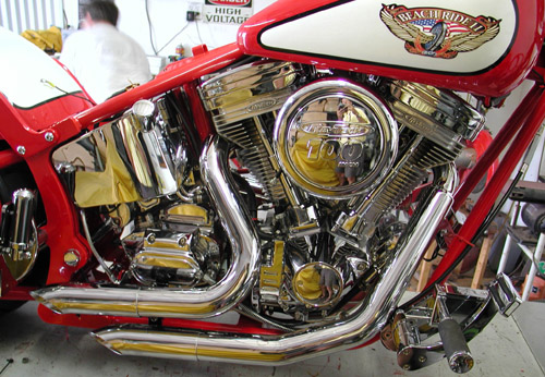
Hang on. Here comes a complete build of a custom CCI Goliath Bike Kit. We built this 100-inch Rev Tech monster in nine days. The bike was assembled to promote the Annual Beach Ride, at the Queen Mary in Long Beach, through the efforts of Custom Chrome, George Hayward and Bikernet.com. We assembled the bike in the Bikernet Headquarters for the children’s charity ride. It was also featured in three issues of American Rider, but this is the extended, unedited version with charts. Before we get started, I want to add an editorial note. If you read this and want to add something, don’t hesitate. We can change the text whenever we goddamn want. If we missed something, you have a special tool, a correction or want to point out what a bunch of baboons we are, don’t stop, send a Your Shot. Let’s hit it.
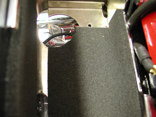
“What the hell,” Nuttboy mumble, “what did you volunteer me for?” He scratched his butt, with a 9/16 open end wrench, as we loaded box after box of components into the garage. If CCI could somehow ship the components without the retail packaging, they would save a fortune. We had a truck load of plastic peanuts, plastic bags and cardboard.
The Goliath is a complete 100 inch, Rev Tech powered Softail kit. It comes with every nut and bolt. “And a few extras,” Nuttboy chimed in distractedly. Also included was a Softail manual and a Softail Parts book. We also referred to the Tim Remus book, “How To Build A Kit Bike”, from Wolfgang Publications.
“The Remus book was the most help, but there were big gaps in information,” Nuttboy grumbled. “We often had to scan the photos in the book in a fleeting effort to figure out a procedure that wasn’t described.” Maybe this series of articles will help.
The entire bike was built in a garage using normal hand tools. A professional shop came in handy on only two occasions: Pressing the clutch together, tire/wheel assembly and balancing.
The frame, wheel rims, and miscellaneous parts were powder coated by Custom Powder Coating in Dallas (214) 638-6416 to match the hue used by Santini Paint (714) 891-8895, for the sheet metal.
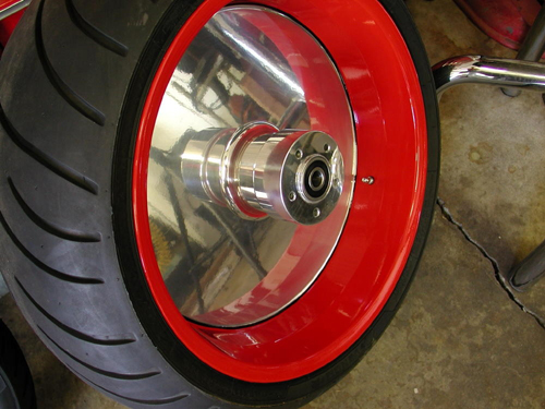
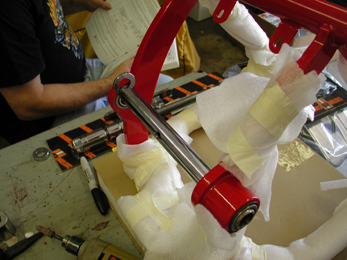
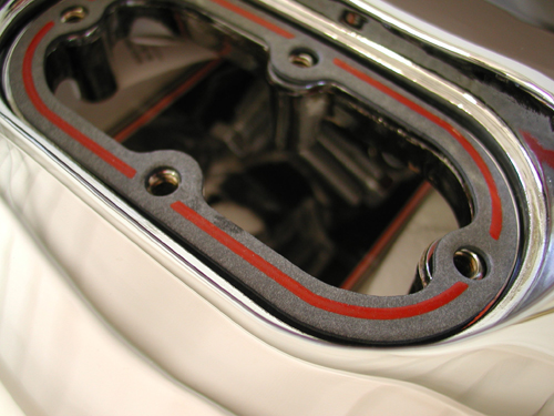
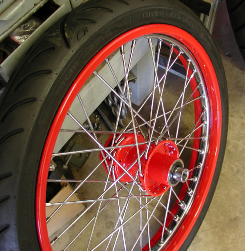
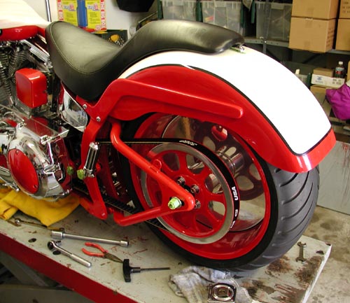
Here’s the massive rear wheel. It was powder coated red on the rim, then clear powdered. Finally George, the Wild Brush, finished the edge with a wide stripe.
“Violent Red I’d call it,” wise-cracked Nuttboy, “it looks hot enough to fry your bratwurst.”
We made sure the tank was pressure tested and sealed at the painter’s. We organized the parts as best we could and once the powder coating was returned Nuttboy shaved off the paint and tape where the motor mounts and tranny mounts were located. Dallas handles frames for American Iron Horse, so they know what to mask, which saved time. Nuttboy started checking the surface around the neck and beating the cups into place with a brass hammer and a massive punch. They must be pressed in completely.

We tried to organize the parts. This was the electrical stack.
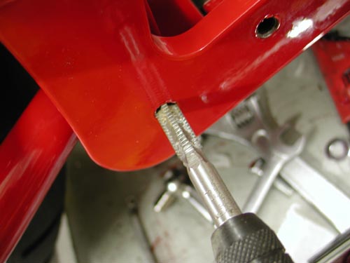
We cleaned the area around the cup area on the neck to make absolutely sure the cups would seat entirely. That’s critical. If the cup seats more while vibrating down the road the front end will loosen and add to crucial elements that could lead to a high speed wobble.
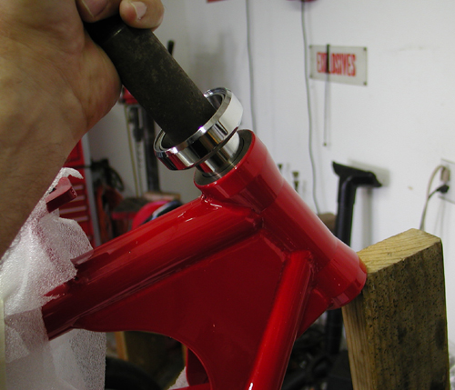
We used a 20-year-old Bikernet punch to drive the cups home. Make sure they’re aligned properly.
You can tell by the changing tapping sound that the cup is fully in place.
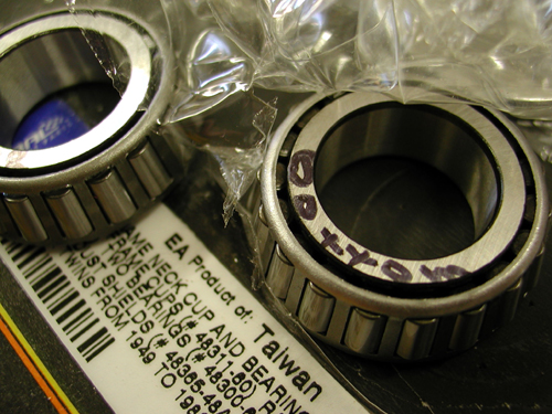
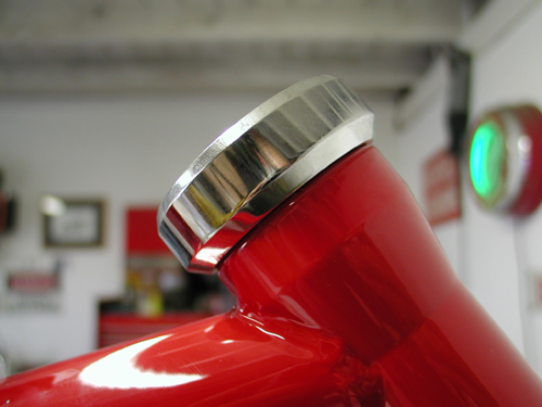
Note the markings to keep matched bearings and races together.
We separated the cups from the bearings but made sure to note which matched bearing fit in which cup, for the most precise fit. Nuttboy pounded the cups in place with a dab of grease to prevent jamming inside the neck.
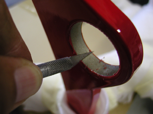
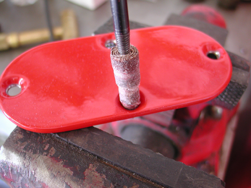
Custom Powder Coating did a fine job of taping off the bearing and motormount areas, but each one needed the edges cleaned.
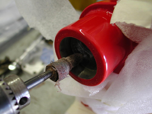
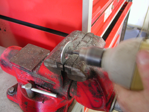
This emery bid worked wonders to clear away paint or soften the edges.
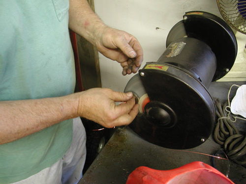
We used a bench polisher to clean the powdered edges on this inner-primary spacer.

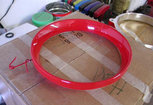
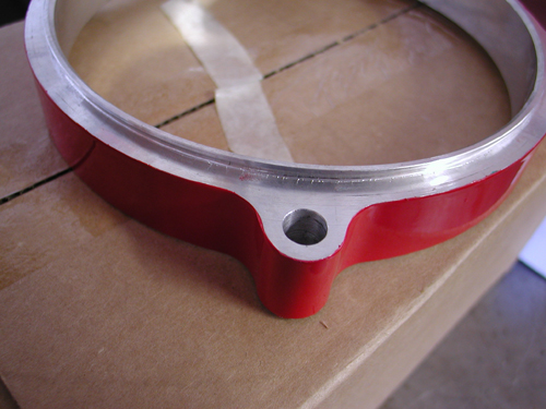
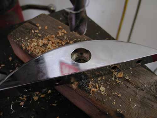
Here’s the red billet headlight ring.
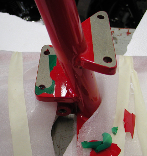
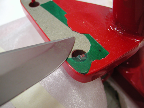
Scraping the tape free of the tranny mount for a solid bond.
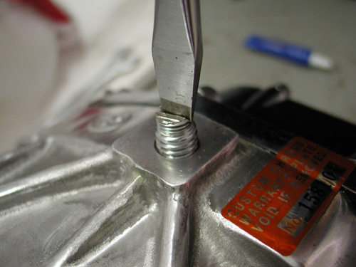
Some of the frame threads needed chasing which eased assembly. Then Nuttboy bolted in the offset Tranny plate.
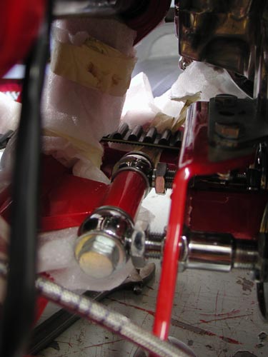
“The swingarm spacing was a turkey,” Nuttboy coughed trying to fit the axle. The swingarm axle came with several spacers, none fit perfectly, and we were forced to make spacers and set the swingarm up several times. He gave up on the swingarm and installed the shocks first then the tranny to make allowances for the studs. One had to be shaved due to the offset tranny plate.
Here’s some improved-shock instructions:
Place the motorcycle securely on a stand so no pressure is on the shocks.
Install the new shocks–the hardware was supplied
You’ll need a preload wrench from a dealership to adjust (94455-89).
The preload comes adjusted to the lightest setting. To increase the preload for heavier riders/loads/passengers, loosen the 11/16 locknut and back it off several turns. Use the 11/16 Harley adjustment wrench to turn the adjustment nut counterclockwise to the desired preload setting. Then tighten the 1-inch locknut. Both shocks must be adjusted to the same equal setting.
The swingarm axle came with a variety of spacers, but no guidance. The widened frame was almost two inches wider, maybe more. We would have loved a diagram.
We grappled with it for a couple of hours, then took a research break. Part of the dilemma was the thick red powder coating on the inside of the frame and swingarm parts.
“The fifth stud was removed,” Nuttboy said, “there’s always a stud too many in the Bikernet garage,” Nuttboy commented. Another stud was shortened for clearance. He tightened the tranny plate down but not the tranny until the inner primary is aligned. Directions indicated an Allen plug to replace the 5th stud. We couldn’t find it, so shifted to plan B.
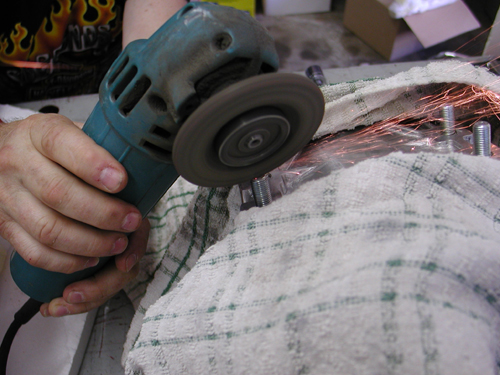
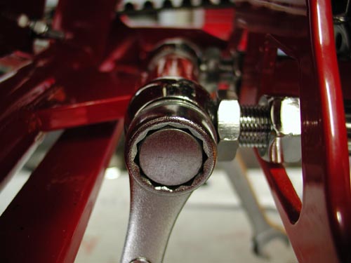
The rear right stud also was ground to clear the shocks due to the offset.
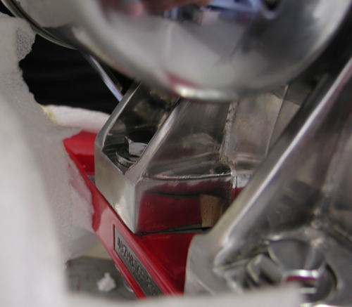
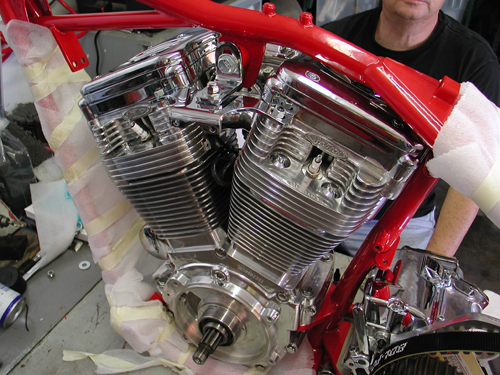
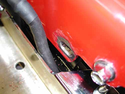
We slipped the engine in from the right. It fit perfectly although Nuttboy had to grind the left rear fin slot, to afford the clearance, for the mounting bolt to fit.
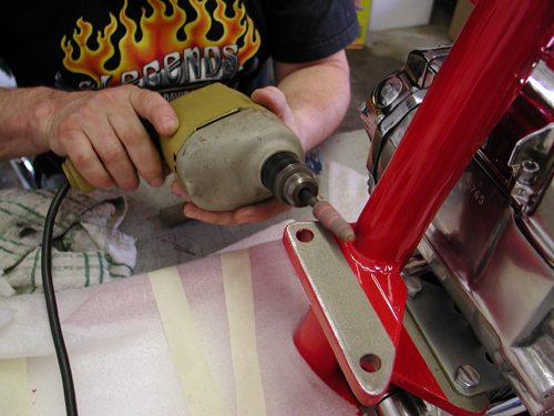
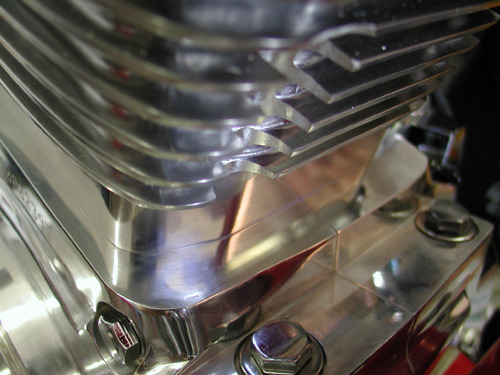
The massive barrels with additional cooling fin area had a slot pre-ground into the rear of the rear cylinder for the motormount bolt, but it wouldn’t fit unless we shaved the bolt or ground one more fin. We ground the fin.
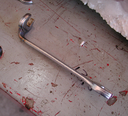
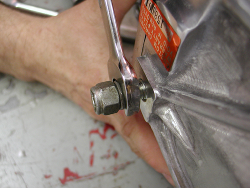
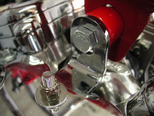
Here’s a 9/16 open end wrench that I bent, with torch heat, years ago to reach that bastard motormount nut behind the inner primary.
We mounted the front motormount bolts in loose at first. With the tranny and engine loose, we used the primary to align the driveline. This move is critical for alignment.
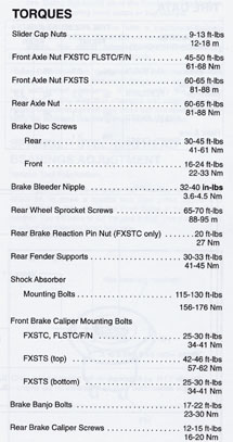
We slid on the inner primary, snugged it down and made sure the engine and the tranny aligned before tightening the motor and tranny mounts down. It’s best to tighten a few bolts, then remove the inner primary, and tighten the final bolts. Nuttboy referred to the stock Softail manual for torque specs (see torque chart at end of article). He made sure to install the rear belt before the swingarm and inner primary. “We still didn’t have the swingarm dialed in,” Nuttboy muttered turning wrenches. “The powder coating was thick and rubbery. This created an issue of tolerance and alignment. We often came to a ‘raise the bridge or lower the river’ type of decision. The swing arm installation gave us a clue, as to the need, to adapt. The instructions were either non-existent or cryptic. So we went with our mechanic’s intuition and marijuana paranoia.”
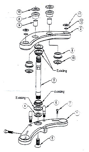
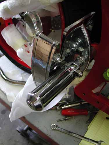
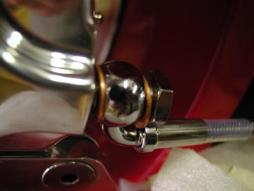
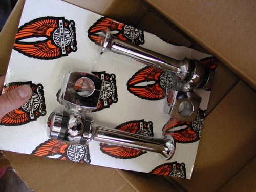
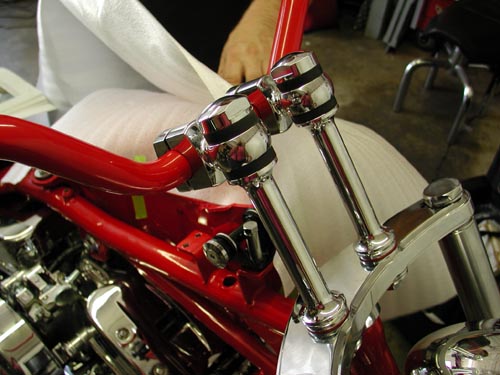
We also installed the front end on the first day. It was a breeze, except… Nuttboy followed the Remus book and kept in mind that the brake tabs run to the rear of the left leg. He dug through tin drawers to find rubber bumpers to slip over the fork stops and prevent the stops from dinging the frame. We decided to switch the bars for Custom Cycle Engineering, 8-inch, old school, dog bone risers and powder coated bars TT bars. “That will come later,” Nuttboy snapped tightening the lower tree pinch bolts.
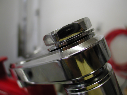
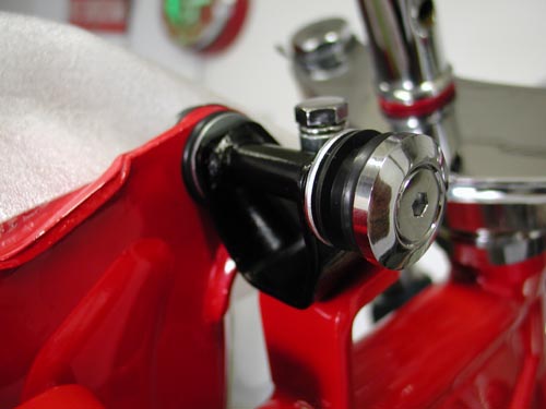
The stem was tightened to the lower triple-tree with a counter-sunk Allen on the bottom. We used the supplied red Loctite on anything that was assembled permanently.
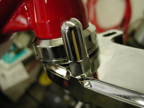
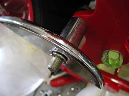
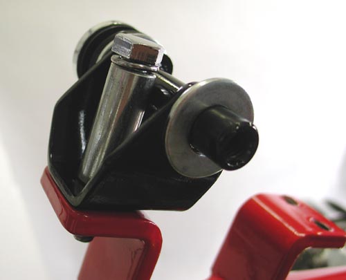
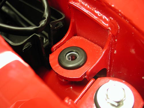
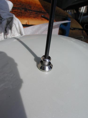
Here’s a fork stop in place. Easy livin’. We covered it with a rubber cap to minimize damage to the frame paint.
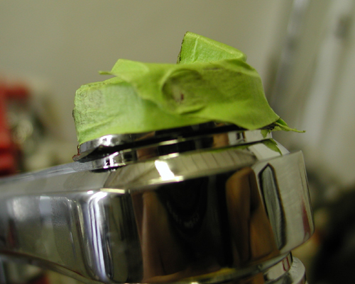
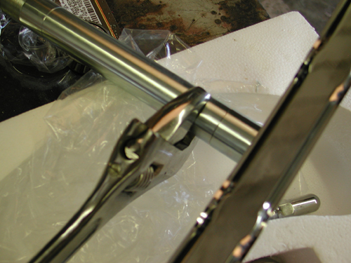
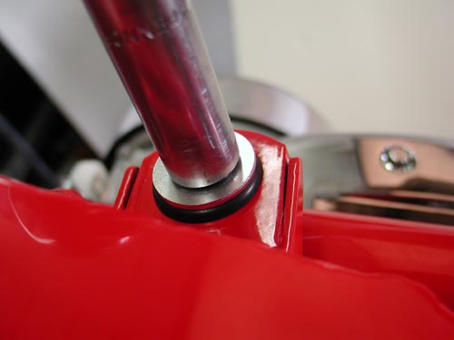
We used green masking tape around chromed fasteners to prevent peeling the plating. A rubber garden hose like washer goes in the top triple tree then a washer. For some reason these gaskets/oil seals loved to peel out or reacted to the fork tube fluid. We installed the caps loose initially, removed them and poured in 12.5 ounces of fork tube lube. Then we discovered that the assembled lower legs came with loose fasteners on the botton and loose drain plugs, so the fork fluid began to leak.
We replaced both fasteners with Tephlon tape for a secure seal.
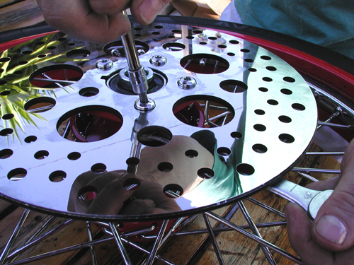
Nuttboy torqued the rotors to specs, 18-20 pounds for the front and 25 pounds for the rear and installed the clean billet caliper. The manual called 12.5 ounces of fork lube. That covered our first 6-hour day. The next day, the oil seeped out of one of the legs and was dripping out of the other. Nuttboy was pissed, “We had to re-seal the drain plugs with Teflon tape and tighten the Allens in the bottom of the legs after removing the front wheel.”
Day two began installing the primary drive. We slipped the stator in place with some light grease on the plug. Nuttboy was careful to face the stator so the plug wires ran comfortably inside the case. We greased the plug lightly so it would slide through the case easily. “Make sure to back out the Allen set screw or you’ll be screwed,” Nuttboy barked. “When replacing the screw, take it easy. It can bore right through the plug and cause a short.” He checked to make certain the regulator plug would connect properly before driving the set screw home.
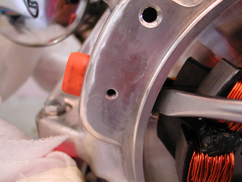
This is a delicate operation. If anything jams, stop and check it. Don’t force the plug, just guide it.
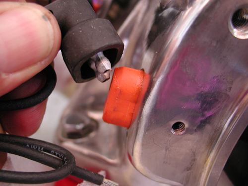
Once the plug protrudes, make sure it gives the regulator plug enough space to make a solid connection.
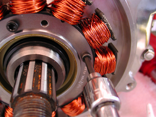
These little Torx fasteners come pre-Loctite coated. Tighten evenly to 30-40 inch pounds.
One spacer slips over the sprocket shaft before the rotor slides down the splines. It’s key to figure out which spacer is appropriate for the year you’re working with.
I compared several diagrams that run down the installation of rotor to make sure the proper washers were installed. The rotor slipped into place without a problem. “The kit came with a variety of shims to space the compensating sprocket properly with the clutch hub sprocket,” Nuttboy said.
“The Custom Chrome Goliath comes with virtually everything including fluids for the primary, forks, tranny and engine,” Nuttboy gagged, digging through reams of packing material. Once in awhile there was a quirk and the Tim Remus book helped. The chain adjuster parts included fasteners and extra parts, which was occasionally confusing.
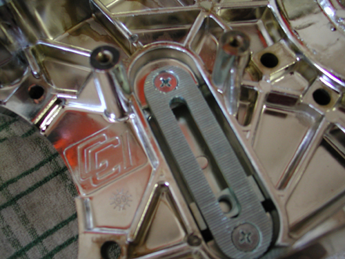
The chain adjuster came with several parts including a U-shaped bracket that would generally run on the back of the base plate. We installed the plate with red Loctite on the screws. Later we discovered that the plate had to be removed, because we should have found the proper chart and seen that it used a carriage bolt instead of the U-bracket. Our mistake.
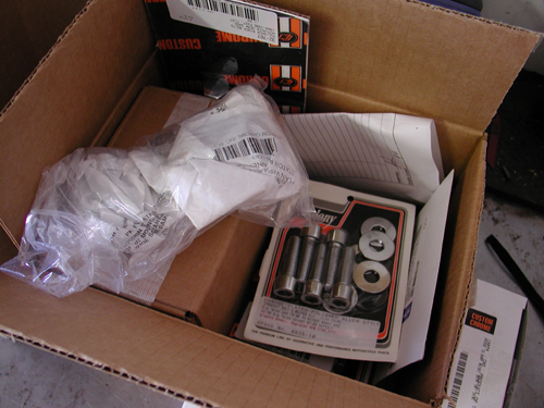
The Bikernet X-Files of fasteners.
“We had an ‘X-Files’ cardboard box for extra fasteners, unnecessary parts, and parts too damned weird to be from this planet,” Nuttboy pointed out clamoring through the box for a solution. “As we assembled the bike, the cardboard shipping boxes flew out the garage door, and the X-Files box overflowed.”
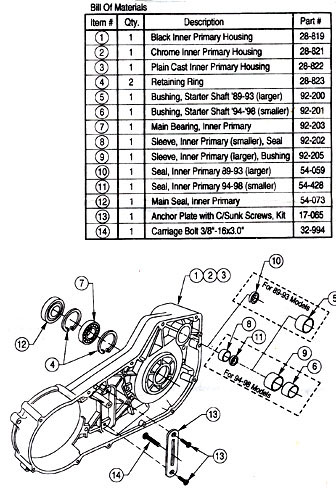
This diagram shows all the elements of the inner primary.
This brings up a key point in building a bike. Read everything first. If we had read Tim’s book from cover to cover, the manual and all the instructions, we would have saved some time. Keep in mind that we built this bike in nine days–part time. We were flying. That’s my goddamn excuse, and I’m sticking to it.
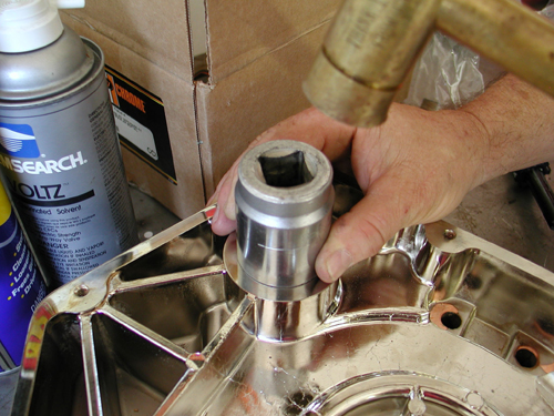
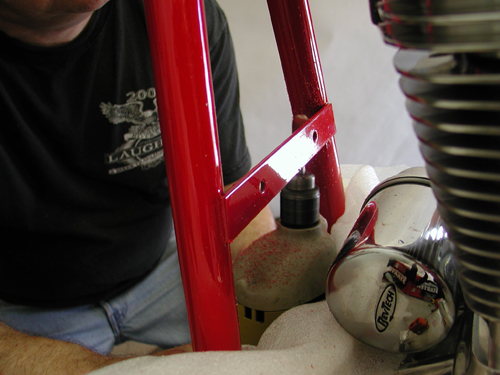
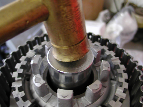
We handled the inner-primary bearing and seal at home with a brass hammer and just the right massive socket.
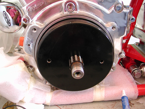
“This was an area where a pro shop came in handy,” Nuttboy commented trying to force the clutch together. Our garage was not equipped with a press. “Installing seals and bushings must be handled with care,” Nuttboy muttered after reading a comment in Tim’s book. Using a brass hammer and a large socket works, but is not recommended. “A good shop,” Nuttboy said loading the clutch parts in the truck, “like Larry Settle’s in Harbor City, California, can handle this aspect in five minutes.” With the bearing and seal in place, in the inner primary, and the proper bushing selected for the starter coupler, we were ready to install the inner primary and torqued the bolts to 20 pounds.
This bushing was also handled in the Bikernet Headquarters.
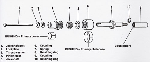
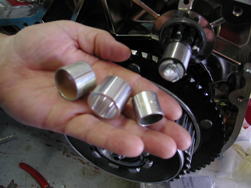
These are a bunch of tricky parts. Follow the diagram carefully.
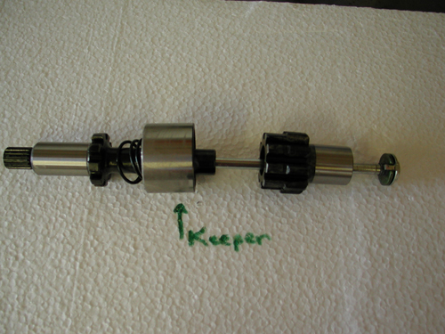
Here’s another shot of the starter shaft components. It’s easy, but make sure you have them in the correct order.

Should slip right in with some help between the inner primary and the tranny.
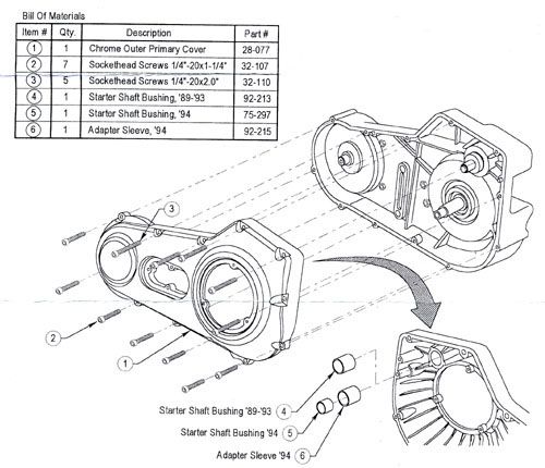
Picking the proper bushing was a key element. Since we didn’t have trememdous experience with various models we used the starter shaft parts as a guide.
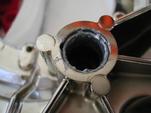
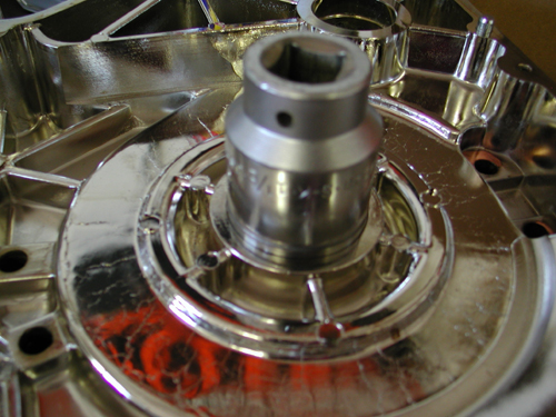
Here’s the outter primary bushing gooped with Never Cease.
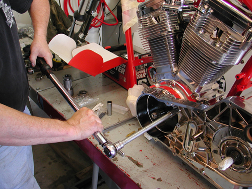
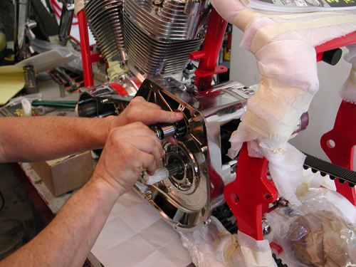
The inner primary was torqued into place. Don’t force it and make sure all the O-rings are in place around the engine spacer.

Here’s that goddamn chain adjuster in place.

Subscribe to American Rider, I did.
“Hold it,” Nuttboy barked from under the lift. “We inspected the edges of the powder coated wide drive spacer, first,” Nuttboy grumbled. “We greased the O-rings for a solid seal. The guys who worked with Tim on his book recommended Never-Cease instead of grease for primary related slippery parts.” The starter gears were a trick and we used the manual for guidance. Nuttboy installed the regulator after cleaning the installation area for a solid ground. He also installed the starter. That blew through another day, 8 hours.
Nuttboy ground off the regulator mount paint with the emery bit for a solid ground.
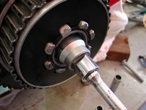
This was a bad and unsuccessful move. Larry Settles pressed the clutch together in five minutes at his shop. We need a press in the Headquarters.
We started the third day with the clutch hub and shell pressed together at Larry Settles’ and the fiber plates soaked in primary fluid over night. Nuttboy installed the clutch and compensating sprockets with the wide drive shaft extensions and shims. We tightened the Clutch hub nut to 70-80 foot pounds of torque and the compensating sprocket nut to 150-165 foot-pounds of torque. Then he checked the alignment of the primary chain and adjusted the shims behind the shaft extension to give us a .004 to .014 tolerance. After Nuttboy adjusted the clutch pushrod, it was time to bolt up the outer primary with a new gasket.
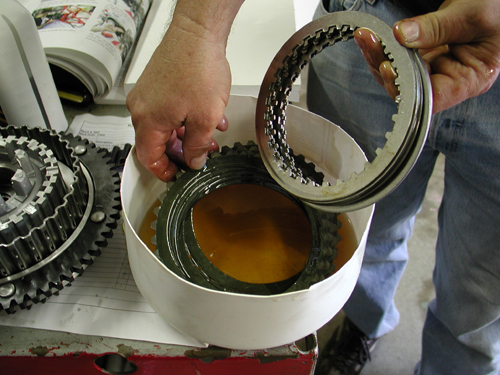
The fiber clutch plates were soaked for 24 hours in primary lube.
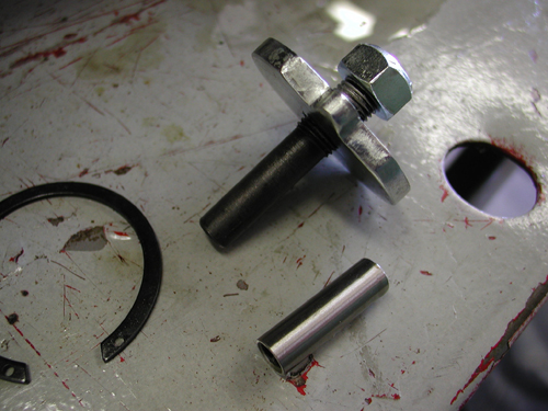
Here’s the pieces used with the clutch pushrod to adjust the clutch. Final pieces to be installed with clip ring pliers after the clutch is torqued into place.
Here’s the compensating sprocket shims. After the clutch is installed and the sprocket with the chain we measured from the chain to edge of the inner primary with feeler gauges to make sure that the distance from the front of the chain to the clutch was no more than .014 inch. If not we needed to adjust the shims.
Here’s the various bushings out of focus.
We cleaned up the countersunk holes for a tight fit.
Ah, the primary locked-up. Don’t forget the fluid.
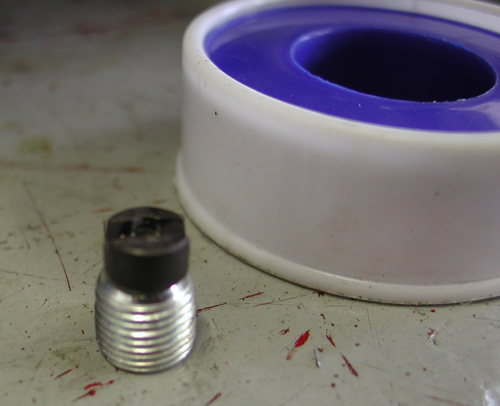
This is the primary drain plug with magnet attached and Tephlon tape in the background.
Primary plug in place. Later we were suspicious and pulled it, shaved off half of the magnet and replaced it. It may have been hitting the clutch.
“Ah, but first,” Nuttboy corrected, “we determined the correct bushing to press into the outer primary for the starter pinion gear. With primary installed Nuttboy bolted in the drain plug with Teflon tape and filled the inner primary to 1/4 inch above the clutch shell lip (with the bike upright) and attached the derby cover with an O-ring.
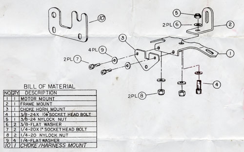
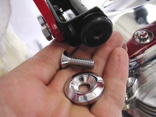
Here are the components involved with the top motormount. Keep in mind that the horn bracket is part of the mixture, unless you’re like me and would toss it in the trash.
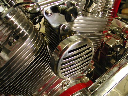
Next we installed the top motor mount, horn and choke bracket. Watch this little puzzle closely. I ended up dropping the horn down some to make for more clearance.
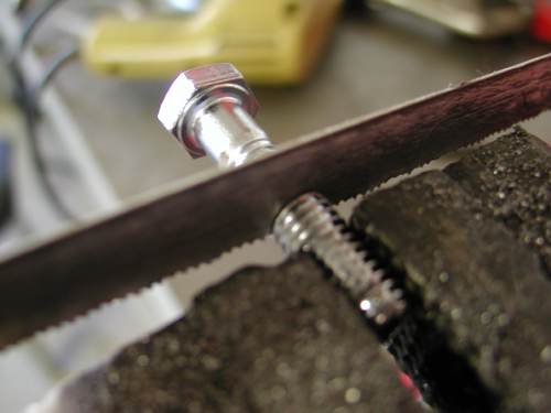
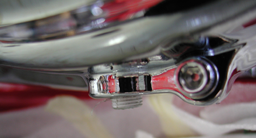
We trimmed a fastener to fit.
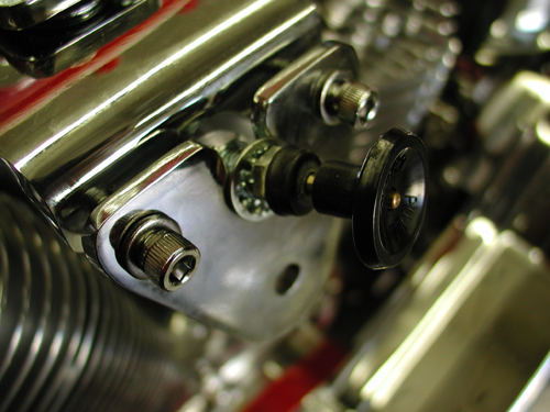
Ultimately we discovered that the gas tank touched the motormount bracket and had to move some spacers around.
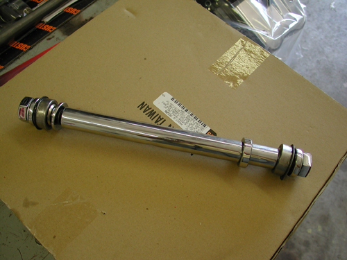
We found the oil tank brackets (unchromed) packaged with the rear axle. We primered them and painted them black.
Nuttboy then installed the battery cables. Tim’s book was helpful determining which cable went where. “It’s good to install them before you attempt the oil can assembly,” Nuttboy pointed out. The oil can brackets were vacuum packed with the rear axle and un-chromed. It was a hunt to find them.” Nuttboy spat. “Who would expect to find oil tank brackets packed with the rear axle?”
We moved onto the front wheel which had been powder coated and cleared by Custom Powder Coating, then George, The Wild Brush (310) 488-5488 pinstriped both wheels to conceal the powdered edge. The front wheel was a breeze using the one long spacer on the right and two short spacers for the left portion of the axle.
Make sure the wheel is centered and tightened down. Then with the supplied shims, center the caliper over the rotor.
“One had a small lip that fits in the seal and prevents it from falling out,” Nuttboy pointed out, his bike building, education expanding. Then we installed the caliper.
One of the most time-consuming aspects of building a bike is hunting and or making shims and spacers. Lotsa tools helps out.
Nuttboy shaving a washer for a perfect fit.
We sought to center the swingarm in the frame by manipulating spacers and shims.
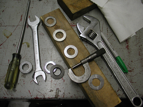
Here’s some of the tools involved in spacer/fitment wars.
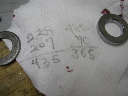
It took some precision calculations to fabricate the perfect fit.
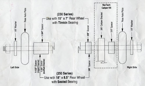
Finally we shifted back to the swingarm and spacing madness. Nuttboy worked the spacers until it was centered in the frame. “Where the shaft was a delicate problem,” Nuttboy grumbled, “the rear wheel was no problem.” He followed the supplied diagram to the tee, although one spacer had to be altered, perhaps due to the thickness of the protective powder coating.
Sure we stumbled from time to time. We don’t build Softails daily, but the Beach Ride Bike was flying together. That summed up day three. Stay tuned as we stumble back into the teetering garage.
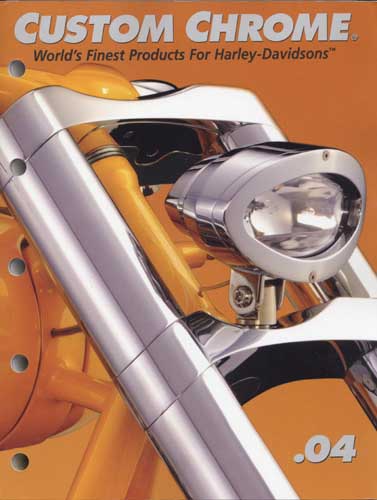
BRAND NEW CUSTOM CHROME CATALOG RELEASED–
Custom Chrome’s new offering for 2004. The California based distributor brings you the most comprehensive product offering in the Harley-Davidson aftermarket! At over 1,200 pages and over 22,000 part numbers, their 2004 Catalog features the new RevTech 110 Motor, Hard Core II, Ares bikekits and noumious frames and forks–everything from nuts & bolts to performance products. It’s the Custom Bike Bible for the year.
ONLY $9.95 + 6.95 Shipping**
Grab a beer, here’s part five of the Goliath Bike Build for the Exceptional Children’s Foundation Beach Ride. This promotional project wouldn’t be possible without the contribution and support of George Hayward, who funded it. The crew of Bikernet.com built the bike with additional hands belonging to a novice American Rider, Nuttboy. His past is too sordid to mention.
The frame, wheel rims, and miscellaneous parts were powder coated by Custom Powder Coating in Dallas (214) 638-6416 to match the hue used by Santini Paint (714) 891-8895, for the sheet metal.

As we wrapped up the third day of construction last issue we had installed the entire driveline front-end and both wheels. We were rocking with the assistance of the Tim Remus book, How To Build A Kit Bike. The book is available in the Bikernet Gulch. Let’s get to work.
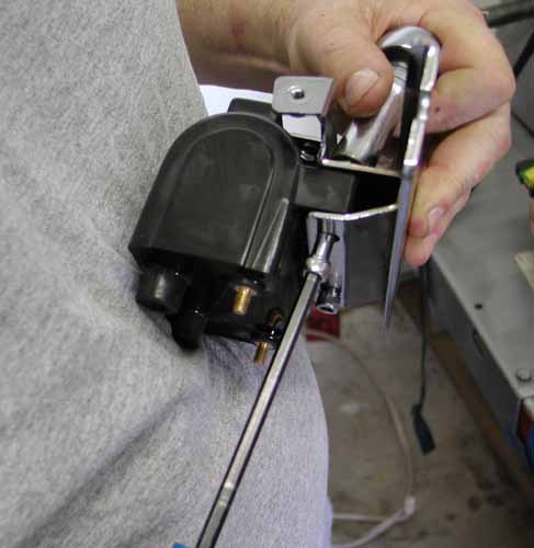
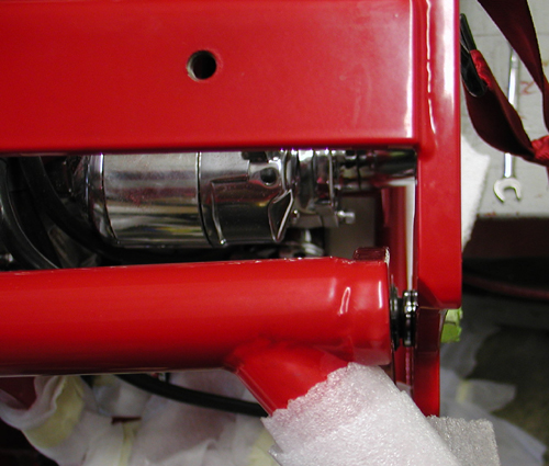
Nuttboy kicked off day four by installing the coil, which would seem a no-brainer. The bracket bolted to the frame stress tube behind the engine. The coil installed effortlessly, then the powder coated cover slipped into place. Unfortunately the cover fasteners didn’t line up.
“Small buzzing tools and a careful hand corrected the problem,” Nuttboy muttered setting the dremel tool on the lift.
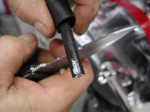
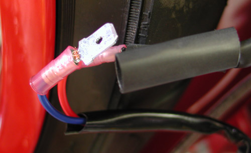
Setting up sparkplug wires isn’t rocket science. Measure them correctly, leaving plenty of slack for trimming. Make sure to pull the rubber boots on first so you don’t have to drag them over the brass fittings.
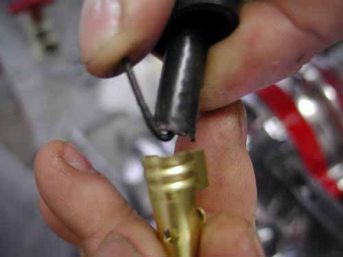
Also, trim plenty of insulation away from the carbon wire to make considerable contact when you bend the center over the end and press it between the insulation and the brass fitting. You don’t want it to vibrate loose and pop free to lose connection.
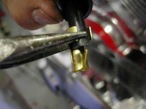
This takes finesse. Pinch them in from the sides then down in the center with needle nose pliers.
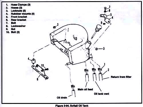
Nuttboy shifted to oil tank installation. The first aspect launched us into an interesting stumbling block. We couldn’t find the brackets for the oil tank? They weren’t with the oil tank at all. We dug through box after box. Here’s the key. If we ordered a complete Santee frame, it would be shipped with the oil tank and rear axle. Since we ordered the entire kit, the rear axle was vacuum wrapped separately from the frame and oil tank.
Guess what was plastic sealed with the rear axle? Yep, the two brackets for the front of the tank and the one long rear bracket. The oil tank is mounted front and rear with rubbermounted studs. Take it slow to figure out what goes where. Install everything loose first.
Since the mild steel brackets were missing in action we didn’t have them chromed or powder coated. That left the two-stage black rattle-can finish. We cleaned and primered them, then after 24 hours, hit them with a couple of coats of gloss black.
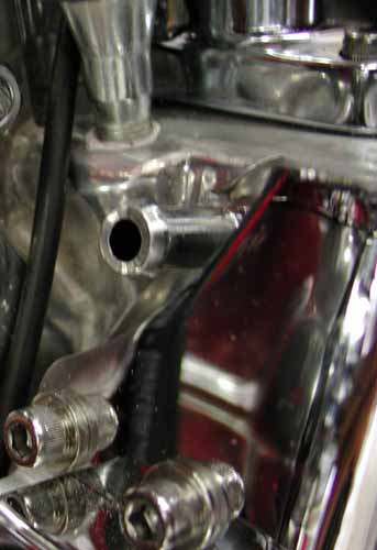
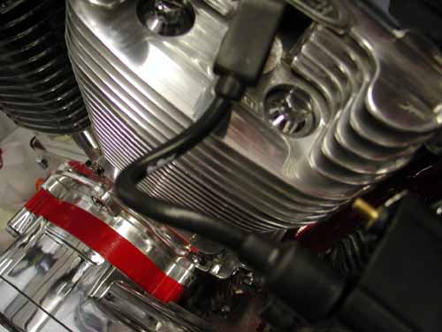
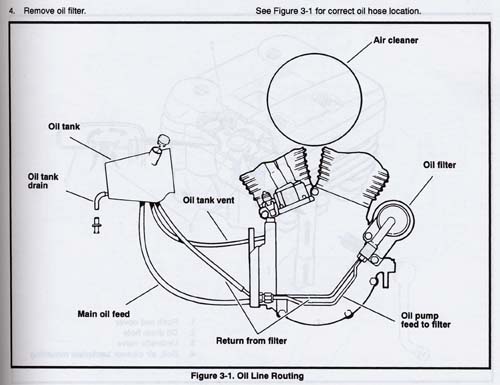
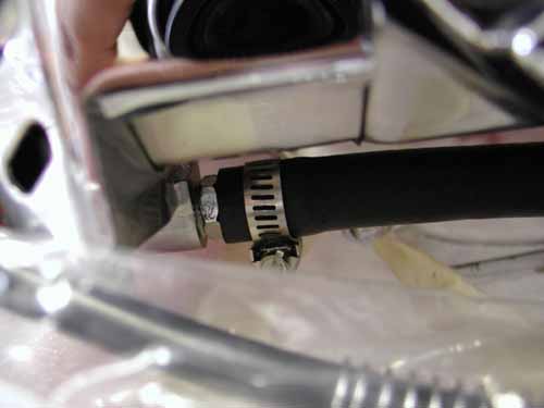
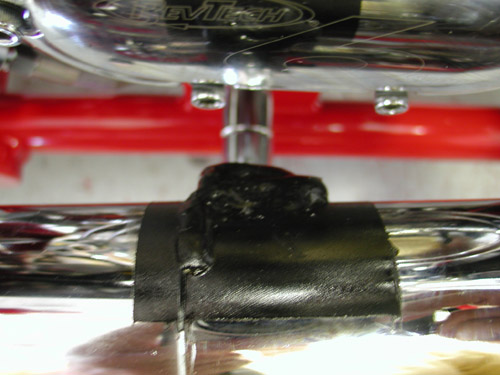
Here’s the case vent that runs directly to the inside front oil tank fitting.
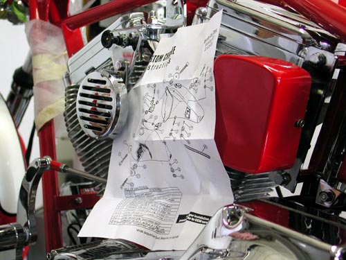
Nuttboy took care to run the vent line first, then the oil pump to filter hose following the diagram that comes with the RevTech 100-inch engine. He made absolutely sure to run lines carefully clear of sharp edges or hot parts. Next he installed the oil line from the filter to the tank.
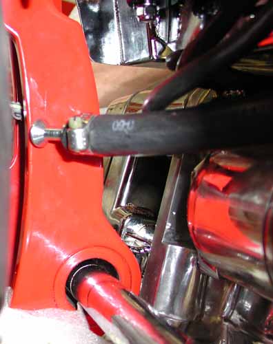
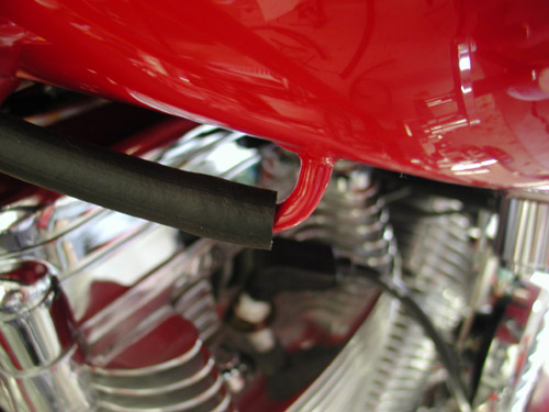
This line runs comfortable under the oil tank to allow draining clear to a funnel. You don’t want it to show, but make it as long as possible.
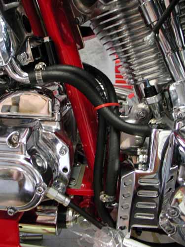
This one was a bastard to run.
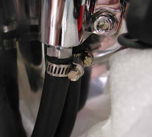
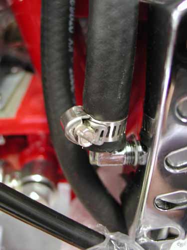
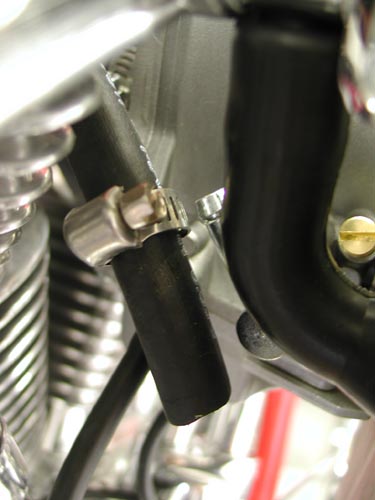
Finally the feed line ran from the tank to the pump, “I don’t know why the it ran around the frame tube,” Nuttboy cussed, “It was a bitch to reach.” He noted that often it’s best to slip the hose clamps over the rubber tubes prior to sliding them over nipples. “Watch for the positioning of the clamp fasteners,” Nuttboy added, “It will save time and frustration.”
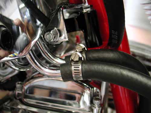
Here’s the return line from the oil pump to the oil filter.
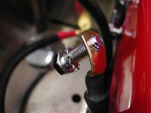
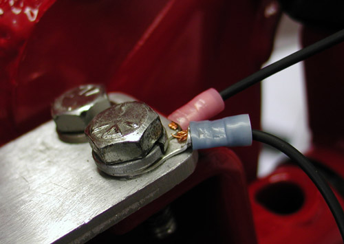
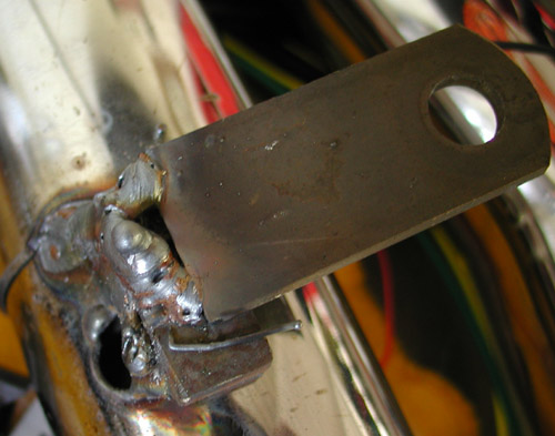
After the oil tank was installed Nuttboy decided to bolt up the ground strap. Here’s one of those reasons for never tightening something before you know it’s in the right spot. He installed a ground strap backward and we were forced to drill out the lug.
Next we picked a spot at the rear of the frame behind the oil tank to use as the ground. We cleaned away the heavy powder coating and sanded it to a bare frame before installing the cable. The cable runs from behind the starter to the frame and from behind the starter to the negative battery terminal for the best possible ground.
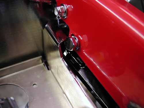
Next he dug through the parts box to find the forward foot controls. The right side connected easily to the frame with blue Loctite. The Left shift lever bracket and kickstand took a 1-inch spacer to make up for the offset primary, then we ran into a problem mounting the kickstand.
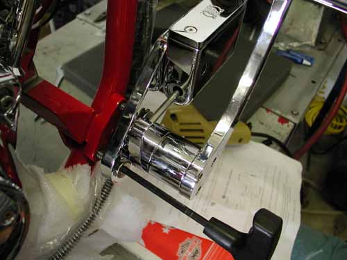
The right side bolted right up with Blue Loctite.
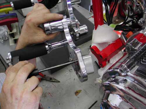
You can see the billet aluminum offset spacer to push the controls out an inch. We also needed longer bolts.
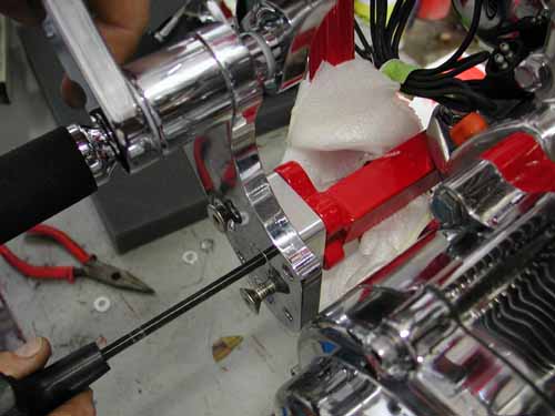
We used additional washers to solve a spacing hassle and moved ahead. All the fluids came with the kit, so Nuttboy quickly filled the oil tank. Another half day had slipped away.
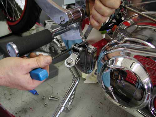
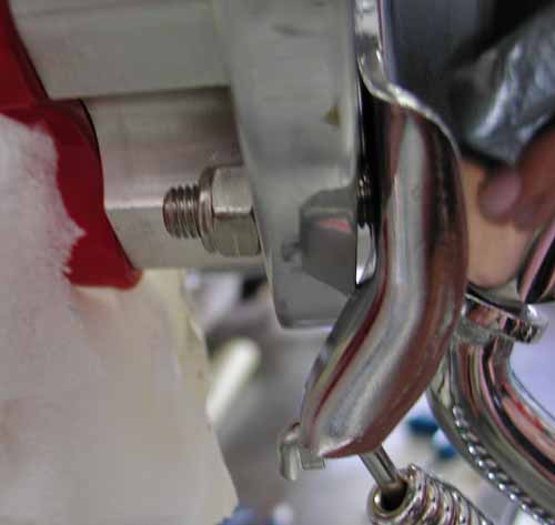
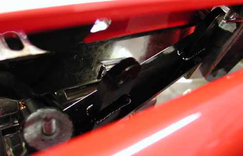
You can see where the kickstand bracket hit the backing plate for the shifter. Rather than grinding the plate we searched for some spacing washers to handle the job.

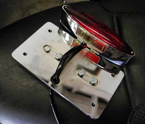
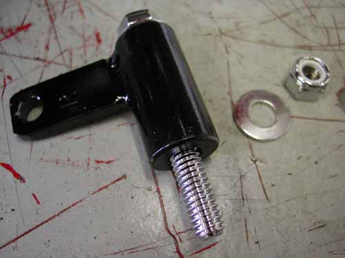
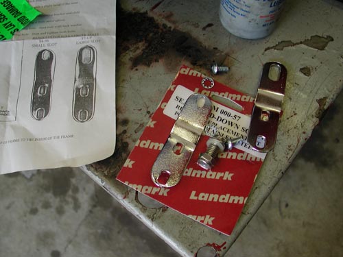
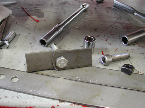
The Goliath kit comes with a massive Rick Doss, side mount, license plate and taillight bracket. We decided to use some aspects of it and tighten the look of the bike some. We drilled the bracket, dug around through drawers for the proper spacer and hardware and redesign the right footpeg mount to incorporate the license and taillight. It worked out tight and right.
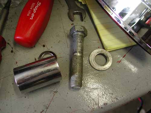
Here’s the spacer we found and the bolt.
We drilled the bracket to 1/2-inch for the footpeg stud, ran the license vertical and were good to go.
That’s it for this week. Stay tuned. We’ll try to drop in a Goliath tech every-other week until this puppy roars to life. If you’re interested in a bike build, order a Custom Chrome catalog first. It will give you tremendous info.
Stay Tuned.
–Bandit
BRAND NEW CUSTOM CHROME CATALOG RELEASED–
Custom Chrome’s new offering for 2004. The California based distributor brings you the most comprehensive product offering in the Harley-Davidson aftermarket! At over 1,200 pages and over 22,000 part numbers, their 2004 Catalog features the new RevTech 110 Motor, Hard Core II, Ares bikekits and countless frames and forks–everything from nuts & bolts to performance products. It’s the Custom Bike Bible for the year.
ONLY $9.95 + 6.95 Shipping**
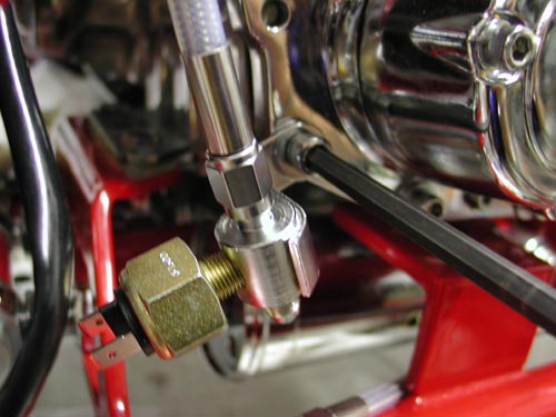
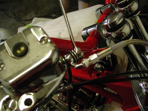
Day five kicked off with a guessing-game tribute. It took us nine days to build this sonuvabitch and nine months to post the articles. No excuses, we’re getting there. We had to figure out which hydraulic lines and fittings went where. Nuttboy set up all the lines loose to test various configurations.
“Take some time,” Nuttboy muttered wondering if he had it right, “there’s no set rule.” There was just enough flexibility with the brake switch mounting to keep us guessing. Three puzzling lines were involved: Front brake, rear caliper to brake switch and brake switch to master cylinder.
Before locking down any lines we decided to adjust the shocks. They can only be properly calibrated with the bike jacked up to relieve any pressure. Then the eyes were released from the swingarm and spun. They don’t adjust from the center.
We set the bike low for looks, and for fender installation clearance. If we had set the bike high, mounted the fender then lowered it, we might have encountered fender rubbing problems. Ultimately we experienced the swingarm smacking the frame rails. I did some research and discovered other experienced builders with similar maladies. We spaced the rubber stoppers out to prevent further problems.
The hydraulic lines were notoriously long, but better long than short. With some creative ability we altered the position of the brake switch to make up for extra line length. Nuttboy Teflon coated fittings without copper or soft O-ring gaskets and tightened them appropriately.
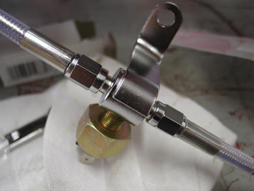
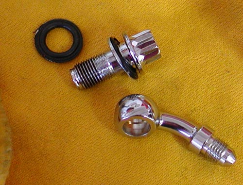
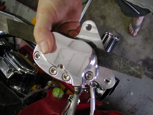
The front brake line was a breeze due to the assortment of fittings and one accurately measured line. The simple Rick Doss bracket with directions installed effortlessly under the bottom triple-tree for a custom touch.
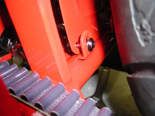
Next Nuttboy installed the speedo sensor in the trans. We searched for a 1/4-inch longer 1/4-20 Allen for the cap and 6-speed spacer. Since one didn’t come with the kit, we used a stainless Allen bolt that we polished for a chromed look.
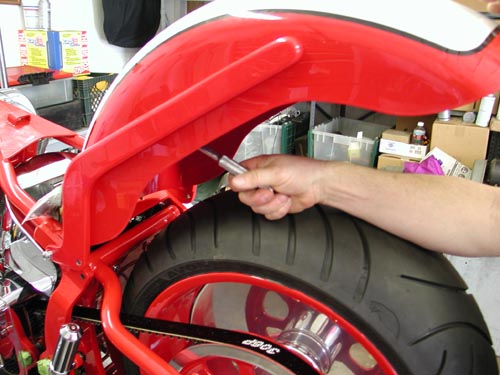
Nuttboy installed the powder coated rear splashguard with CCI supplied chromed fasteners. Since it wasn’t chromed we went with powder-red for a matched look. “Keep in mind,” Nuttboy spoke up after his second beer, “the splashguard goes on inside of the swingarm tabs, not the side closest to the tire.” We burned through another four hours and ducked out of the Bikernet headquarters.
BRAND NEW CUSTOM CHROME CATALOG RELEASED–
Custom Chrome’s new offering for 2004. The California based distributor brings you the most comprehensive product offering in the Harley-Davidson aftermarket! At over 1,200 pages and over 22,000 part numbers, their 2004 Catalog features the new RevTech 110 Motor, Hard Core II, Ares bikekits and noumious frames and forks–everything from nuts & bolts to performance products. It’s the Custom Bike Bible for the year.
ONLY $9.95 + 6.95 Shipping**
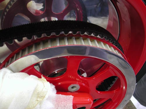
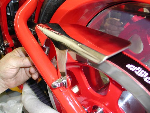
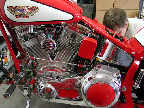
Day six, we checked our seven-day deadline. We had one day remaining. The powder coated pulley arrived from Texas with the edge polished and cleared. It was a nasty touch to the overall look of the bike. The Goliath came with a solid narrow pulley to match the massive rear wheel, but we decided on a change from H-D to add some detail. Not bad.
“I got in trouble,” Nuttboy muttered shuffling his boots on the deck, “I installed the pulley bolts in haste and dinged the swingarm paint above the axle with the ratchet extension.” By moving the wheel back, with the axle adjusters, clearance was enhanced. Nuttboy tightened the red Loctite touched fasteners to 55-65 foot pounds. The brake rotor was fastened with blue Loctite to 25-30 foot pounds of torque.
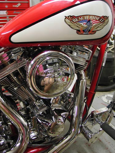
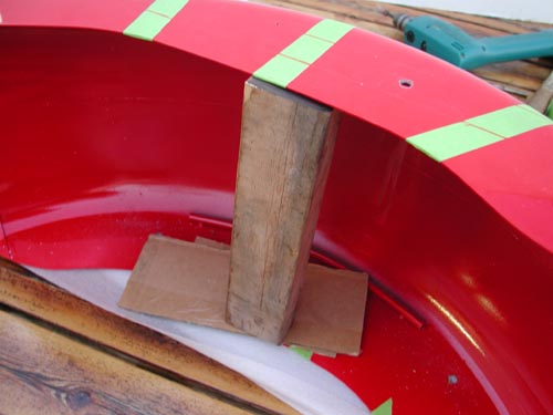
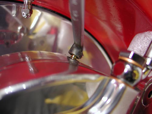
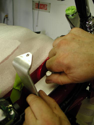
George delivered the sharp sheet metal from Santini Paint, and we quickly jumped the custom tank and suddenly noted that the top engine motor-mount position had to be adjusted for clearance. First off, we pried rubber grommets into the tank tabs using a wooden wedge to prevent damage to the paint or grommets.

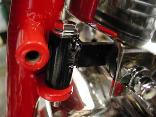
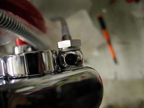
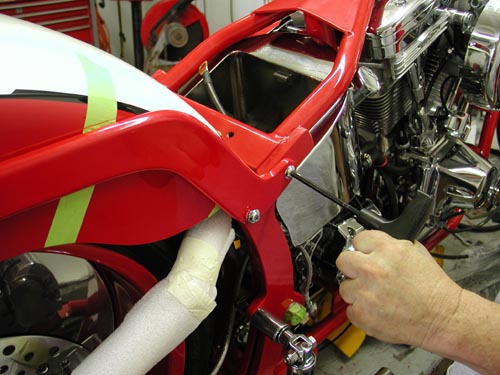
Nuttboy installed the tank bracket and one side of the tank then chased the powder coated threads on the frame backbone. He installed the petcock considering the angle and position of the nipple and how the hose would route to the carb. Next he installed the gas line, the fuel filter, and the gas caps.
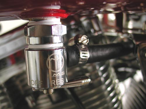
“Note,” Nuttboy interjected, “that the left gas cap has left-handed threads.” The bottom of the petcock was also left handed. “Don’t tighten them to the base,” Nuttboy added. “We centered the fittings in the threads. Then with Teflon coating the threads I screwed it into the tank bottom.” If the petcock wasn’t aimed properly we loosened the tank collar, aimed it and tightened it down. Another day slipped away.

Day Seven
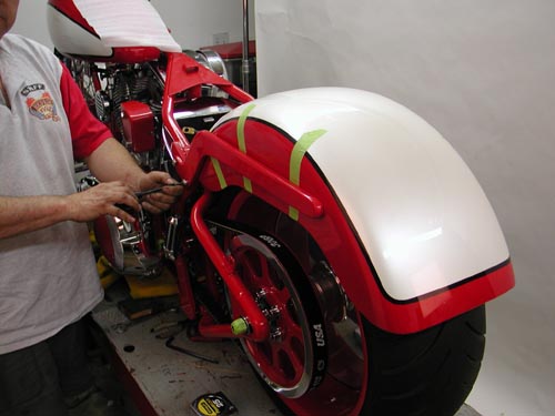
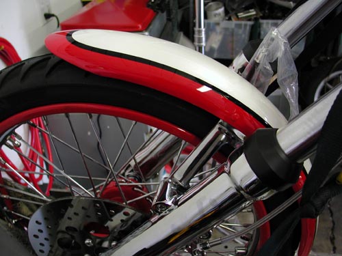
Day seven started with templates, our lovely female assistant, made of the fender rails and marked mounting holes. We installed the rails loose and masked them to prevent damage to the sheet metal. We created 1 1/4-inch spacers, taped them to the tire, made sure the wheel was aligned and removed the jack. We also adjusted the belt, so that the wheel was in running position. We chose 1 1/4 inches for the following reasons. The bike was lowered to the point that it had less than an inch of travel, maybe 3/4-inch. If it bottomed it still wouldn’t hit the fender by 1/2 inch. Keep in mind that there’s a seat bracket stud under the fender. Clearance was needed.
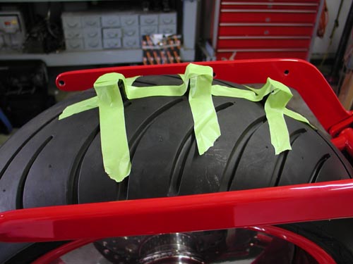
“This was a tough one,” Nuttboy said, “There wasn’t any specific fender mounting guidelines. We used the seat, styling looks and fender to tire spacers to indicate fender position.” I’m still not sure we did it correctly. Note the fender rail position, although it fit the seat perfectly.
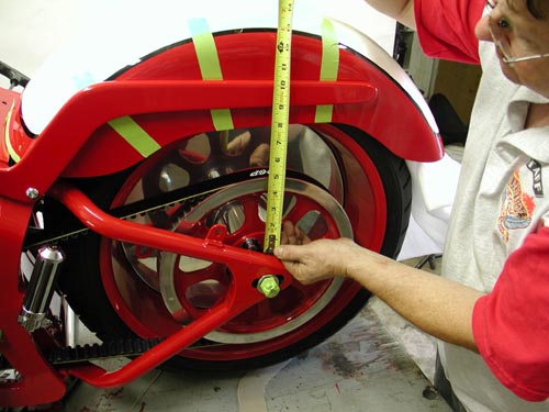
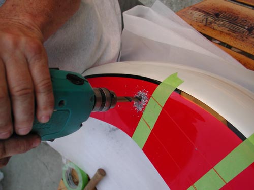
Using a grease pencil we marked the position of the fender rails on the fender, then the templates were used to note the position of the mounting holes. “First,” Nuttboy added with a bark, “drilling the mounting holes should take place before painting to prevent goof ball damage to the paint job.” He was right. Position the fender first, drill the holes and then paint the sucker. We had a screaming deadline an all the components rolled to powdercoating and paint before we could fuck with them. Ah, but George took the rails out to a machinist and had them radiused for a more refined look.
It’s helpful to drill the cardboard template and make sure that it is marked as exactly as possible. Then center-punch the fender and drill the first hole with a small bit. “Pray that the holes line up,” Nuttboy added. They didn’t and some monkey-business was necessary. That ended day seven.
BRAND NEW CUSTOM CHROME CATALOG RELEASED–
Custom Chrome’s new offering for 2004. The California based distributor brings you the most comprehensive product offering in the Harley-Davidson aftermarket! At over 1,200 pages and over 22,000 part numbers, their 2004 Catalog features the new RevTech 110 Motor, Hard Core II, Ares bikekits and noumious frames and forks–everything from nuts & bolts to performance products. It’s the Custom Bike Bible for the year.
ONLY $9.95 + 6.95 Shipping**
Day Eight
Day eight started at 11:30 a.m. when Nuttboy drilled the seat bracket hole, being careful not to drill through the tire. “Care must be taken mounting the seat grommet,” Nuttboy added. “There was a good 3/16-inch of bondo on the top of the fender.”
We were rockin’. We cleaned the fender holes, installed the bolts to the rails, loose and installed the fender on the frame with the rails attached, checked the fender location, tightened the rear fender bolts then rocked the fender, attached to the fender rails, forward and tightened the remaining bolts. Finally Nuttboy tightened the Allens holding the rails against the frame.
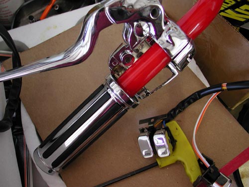
We moved right onto the powder coated handlebars and discovered that the throttle wouldn’t slip over the coating.
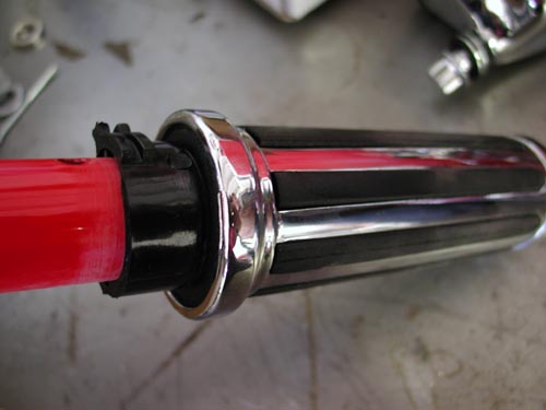
“Sanding was required,” Nuttboy explained. We didn’t use the pullback bars that came with the kit and replaced them with TT-bars and 8-inch Custom Cycle Engineering traditional dogbone risers.
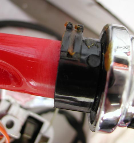
The bars, controls, switches, clutch and throttle cables are a bear. “Take your time,” Nuttboy muttered remembering the process. “I could have used four midget hands easily.” The right side is more complex because it encased throttle cables and throttle tension adjustment fasteners.
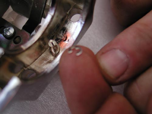
The tension screw was slipped into the base then Nuttboy struggled to fit a very tiny C-clip onto the shaft, so the adjuster could never vibrate out.
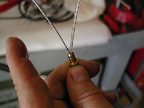
“Lube the cables before installation with a thin oil or silicone lubricant,” Nuttboy muttered. The throttle cables have two different diameter housings so you can’t go wrong. The cable with the spring on the end is the return cable. Make sure the throttle cables are routed cleanly, no binding.
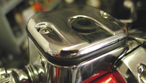
We were into our eighth day when we used the gravity method of bleeding the front brakes. We filled the master cylinder, pumped carefully and allowed the air bubbles to escape through the reservoir.
While it did its thing, we turned to the wiring. We’ll get to final aspects of the Goliath masterpiece in the next couple of weeks. Hold us to it. If you don’t see the wiring tech posted send me an e-mail. We need to wrap it up and go for a ride.
That’s is for this week. See you next time.
–Bandit
Okay, we’re late launching this, like by several months. I apologize and I’ve wired another bike between this bastard and now, so my memory fades. This predominately, took place on the ninth day of the build. Hell, we built the bike faster than we wrote or launched the articles–go figure. I prefer to wire bikes with few bullshit, little switches and gadgets that could leave me alongside the road. This called for nearly stock Softail wiring, although we did ditch the turn signals. The absolute keys to wiring are care, patience and a sketched out plan.
Draw a pencil sketch of the bike and where the components are positioned. The Thunder Heart wiring system came with three schematics. We had to figure out which one was appropriate for this scoot. Once we had it (Typical EHC Softail Wiring), nailed down wiring moved along .
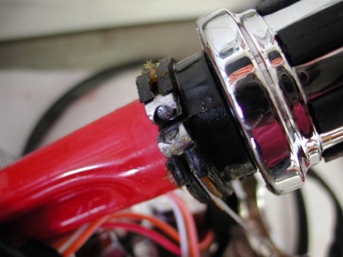
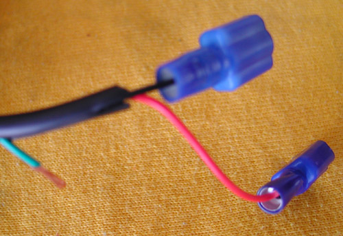
“Yeah right,” Nuttboy spouted, “the headlight wires were not marked high or low beam, neither were the taillight wires or coil wires.” Some testing was required. The directions called for viewing the main circuit plugs from the mating end. “That wasn’t the case and we lost time, damaged the connectors, plus disassembling at the connector plugs is a bear,” he said and gulped his Corona. Fortunately we soldered each connection for a secure, lasting working fit.
The Thunder Heart consists of five major components. There are four harnesses: one for each side of the handlebars, one front harness, and one rear harness. There is also one central harness controller.
“They also pack in all the shrink-wrap, tie-wraps and connectors we needed,” Nuttboy added.
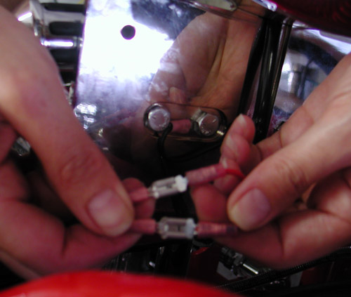
Each harness plugs into the central control unit. “We attached each wire to the terminal plugs,” Nuttboy said cringing. Individual wires are pushed through the backside of the plug. Then the connectors must be crimped into place and finally pushed into the plug base.
“We could go on about the wiring all night,” Nuttboy sniveled.

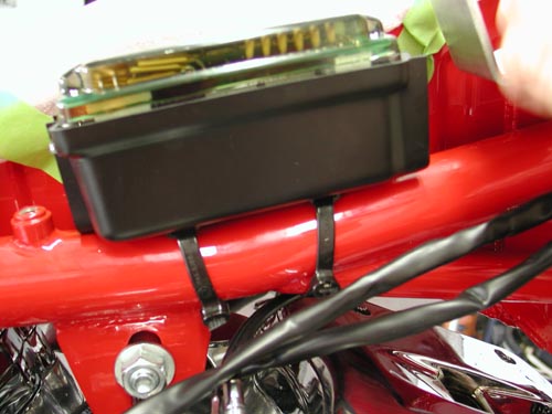
It’s true, but if you follow the code above and read the instruction, then take your time, you’ll be pleased with the outcome. The instructions call for mounting the Split Tank EHC control unit on the top frame tube between the gas tanks. The black plastic mounting base is molded to fit the tube radius and slotted to accept zip tie fasteners. The EHC latches onto the mounting base via the three mounting tabs so that the diagnostic instructions are visible with the dash removed.
With the EHC mounted, attach the rear harness connector to the EHC mating connector. Notice that each wire is labeled according to its function. Route each wire to its destination, but do not cut to length just yet. Keep wires bundled together until they need to break off to their destination. Try to minimize the number of branches from the main harness by combining wires that branch off closely in one larger branch as they will make the heat shrink easier to apply later.
Use electrical tape to construct branch points and to temporarily attach harnesses while fitting is done. Remember to allow extra length for suspension movement or strain relief when locating attachment points. Take care to route harness away from sharp edges, surfaces that may pinch wires or hot pipes. Wires not used should be terminated at the connector to prevent short circuits. Repeat this procedure for the front harness and the right/left control harnesses. When all wires are routed and the harnesses are temporarily attached at their mounting points, cut the excess length from the ends of the wires leaving them approximately 3 inches too long for the final fitment.
Note: the horn and aux power circuits are found on both front and rear harness connectors to allow for different mounting locations. Use the most convenient one for the horn, both aux power circuits may be used, or not, as needed.
Once the harness has been trial fitted to the bike, remove it for the next step, which is to apply the heat shrinkable tubing. Starting from the main connector, cut a piece long enough so that it extends 1-inch past the first branch intersection. This extra length will allow the tubing for the branches to slide into the main tubing. This creates a smooth transition to the other legs of the harness. When a tubing section ends at a termination point (connector/terminal) slide a long piece into the main tubing and then cut at the end of the wire (taking off the last 1/4-inch or so of wire as well).
With the heat shrink tubing installed, use a heat gun to shrink the tubing starting at the main connector and working to the other end. Now refit the harness to the bike attaching the main connector to the EHC first, then attaching the harness to the frame where necessary. Finally, cut the ends of the harness to length allowing room for motion and strip the ends. Attach the terminals to the wire ends and use the heat gun to shrink the strain reliefs (if no shrink tube is attached to the terminal use the 1-inch pieces supplied in the kit.)
The EHC is designed to control LED type dash indicators. LEDs are brighter, vibration resistant, more power efficient, usually need no replacement and are generally easier to mount on a custom bike. When a Thunder Heart LED indicator panel is used, simply find a suitable mounting location and plug the supplied cable into the EHC.
Day nine started with Bloody Marys at noon. We wired the speedo to the tranny using separate connectors from what the kit offered. We ground the instrument dash to the frame.
“This is all a trick of taking the time to route and combine the wires carefully,” Nuttboy added wringing his hands.

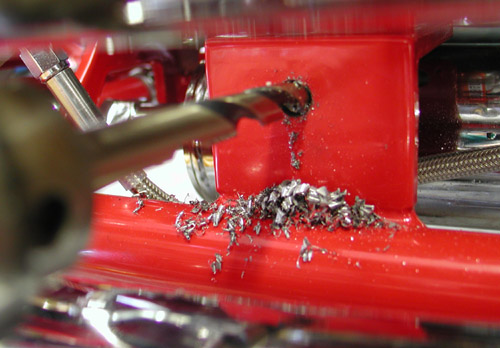
The dash was tricky to align for mounting and we fought it for a half hour. “We carefully drilled and taped the 1/4-20 hole in the frame,” Nuttboy pointed out, “to mount the rear of the dash.” We took a break to chase women then returned to the fray.
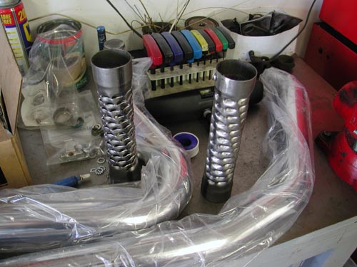
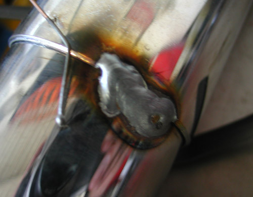
Next we cut the supplied Samson baffles in half to prevent over restricting the big straight pipes, then cut the pipes slightly to even the length and attached down-turned muffler tips.
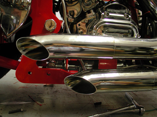
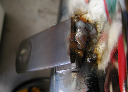
Actually San Pedro Muffler helped us with the modified exhaust, which we mounted to the right side transmission bracket for a clean, secure and light assembly.

We couldn’t leave the pipes alone. They were 2-inch and bone straight. We added some baffle for performance back pressure downward tips for style and a respectable exhaust tone.
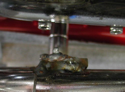
We also modified the Doss taillight (that is designed to run on the right side unlike most side-mounted lamps) and passenger peg for a tighter look. The tinkering and break-in period was upon us.
“Damn,” Nuttboy shouted from the garage. “We forgot the cross-over vent tube between the gas tanks. “
Watch out, when we reveal the finished product, the co-workers and the cheer-leading team of San Pedro alley punks. Don’t miss it. I swear, in the next couple of days.
BRAND NEW CUSTOM CHROME CATALOG RELEASED–
Want the Custom Chrome’s new offering for 2005. The California based distributor brings you the most comprehensive product offering in the Harley-Davidson aftermarket! At over 1,500 pages and over 25,000 part numbers, their 2005 Catalog features the new RevTech 110 Motor, Hard Core II, bikekits, frames and forks–everything from nuts & bolts to performance products. It’s the Custom Bike Bible for the year. No, this is not the latest book, just click on it to find the real deal.
ONLY $9.95 + 6.95 Shipping**
** Price may have changed.