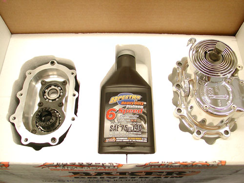
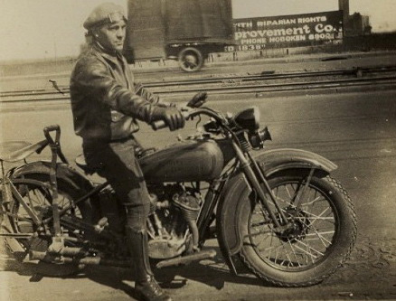
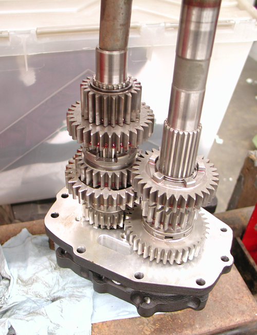
This is one of those shop quiet times installations. You want to make sure all the stars are aligned for this one. Stroll outside the shop with an icy Corona and look to the heavens for inspiration. Sturgis was looming and since this bike was all about vintage I needed a kicker system. I've installed the Muller system from Germany. I've wrestled with a custom chrome 5-Speed kicker transmission into my 1956 Shovel, a very rare motorcycle, so I'm not without some experience. But Baker took the kicker development to a new stronger level, which involved removal of the entire gear set, replacing the trap door and more. I never held an entire gear set in my nervous hands, like a man holding his newborn baby.
Having an inexperienced wrench write a tech tip has it's ups and downs. He could fuck up everything, but on the other hand he'll write about it, so you won't make the same bullshit mistakes. I know first hand that if you've performed the same task a dozen times, the details become second nature and usually are not documented properly. There's my Zen notion for the day, oh humble gods of Baker Drivetrains.
On top of Sturgis pressure, and the unknown Galaxy of emotions, my Epson Camera was acting up. It's been the best for shop techs, beyond Canon or Nikon, but that's another story. I'll scramble my thoughts between data from the Baker team of experts.
First, here's a list of the applications available for this modification:
• 1990-2006 Softails™, FLT/FLH™, and FXR™ models
• 1991-2005 Dyna™ Models
• BAKER DD5 complete and builder’s kits.
IMPOTANT NOTES TO BE CONSIDERED
• BAKER Factor 5 Kicker will not clear most stock exhaust systems due to the extended length of the transmission door and kicker. Most true duels usually fit FLT/FLH models. Rear pipes that route away from the right side of the transmission usually fit.
• The kicker arm will not clear the stock right side passenger floor board on FLT/FLH models. Installation of foot pegs or smaller footboards are required.
• Twin Cam models require installation of a cam-based ignition. See BAKER 2008-2009 Supplement for ignition alternatives or consult a BAKER sales tech.
• Fuel injected models require retrofit to carburetor.
GETTING STARTED The BAKER Factory 5 Kicker kit is designed to be easily installed by any competent mechanic or dealership technician. Having your H-D factory service manual is required for this installation as it is referred to in many sections of the instructions. While this kit is made to be as easy as possible to install there is no substitution for experience. To install the F5K kit, disassembly of the transmission down to the gearset is required. We recommend reading through these instructions, to the end, before proceeding with installation process.
TOOLS, RESOURCES, REQUIRED PARTS
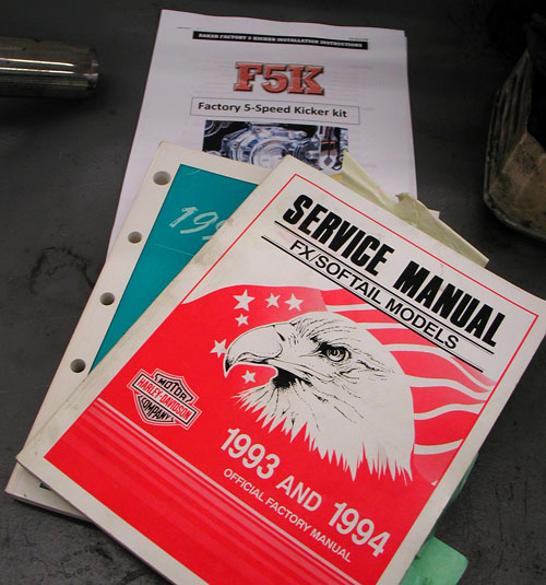
• Factory Service Manual For Your Motorcycle
• Factory Parts Manual For Your Motorcycle
• Common American sockets and open end wrenches
• ToolB-56, BAKER Inner Race Service Kit or H-D equivalent
• Hydraulic Press
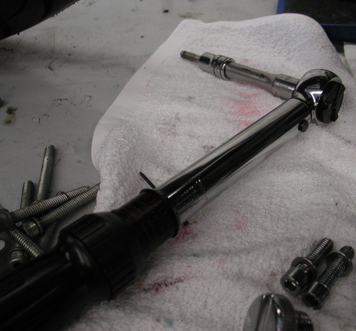
• In-lbs Torque Wrench
• Brake Bleeder Pump (for hydraulic type)
NOTES: HYDRAULIC VERSION ONLY
To complete the Installation of the hydraulic F5K, the following parts will have to be procured to complete the job:
• Hydraulic Fluid, BAKER Recommends: H-D Dot 5 Brake Fluid, PN 99902-77
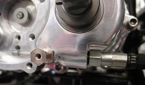
• Correct length AN -3 Brake Line
• 10mm Banjo Fitting & washers for both ends of brake line
• 3/8”-24 Banjo Bolt for the side cover end of the brake line
• 11/16” Diameter Bore Hydraulic Clutch Lever Assembly or H-D
GEARSET REMOVAL
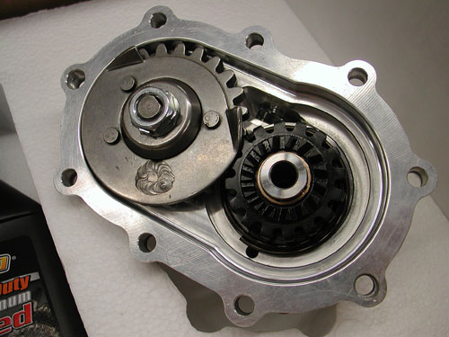
To remove your existing gearset, refer to your Factory Service Manual in section 7, Mainshaft/Countershaft removal. Follow the trap door/gearset removal procedure. Hint: with the stock side cover off, remove the nyloc jam nuts from the ends of the shafts BEFORE the trap door/gearset assembly is drawn out of the transmission case. A ½” impact gun works really keen for this task. Leave the main drive gear in the case.
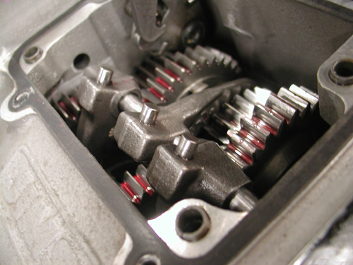


The top needed to be removed from the tranny, then the shifting drum (4 Allen bolts). With the front of the transmission removed some shifting fork shafts will slip out through the trap door in the front. Sometimes the sprocket or pulley can be removed and there's an Allen plug under the sprocket, in case the drap door doesn't have a hole in it.

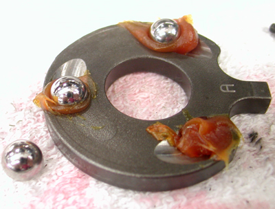
DISASSEMBLING GEARSET
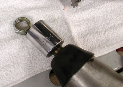
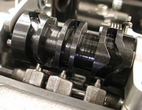
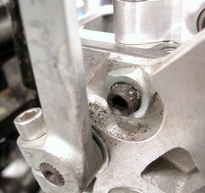
Once the trap door/gearset assembly is out of the transmission case, put it on a soft towel on a clean bench. If that pesky right ‘C’ dowel is stuck in the door, remove it by tapping it through with a hammer and a punch or pulling it through with a pair of vise grips. This will allow the gasket side of the door to sit flat on the support beam of the hydraulic press.
With the gearset facing down and the gasket side of the door of the support beam of the hydraulic press, press the end of the mainshaft down 1/8” and then do the same to the countershaft. Alternate pressing on the ends of both shafts (1/8” at a time) until the shafts fall out.
IT IS VERY HANDY TO HAVE A SECOND PERSON CATCHING THE SHAFTS AS THEY FALL OUT.
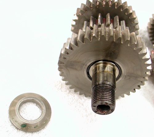
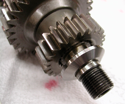
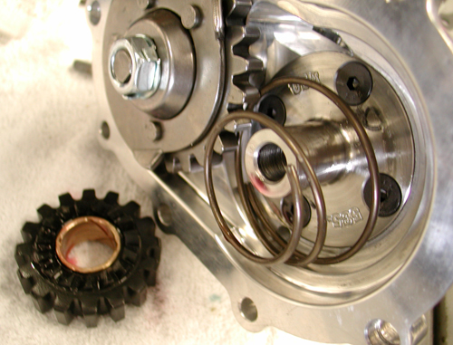
Do not allow the shafts to fall and hit the ground. Remove the conical thrust washer on the mainshaft as the ratchet hub (PN 308-5) will replace this part during the re-assembly process. Keep the stock conical thrust washer (the one without the step on the back side) on the counter shaft. Put the ‘prepared’ gear clusters on the soft towel on the bench.


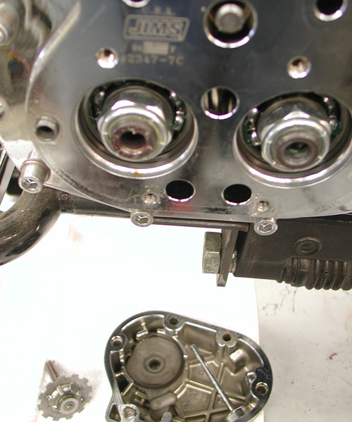
BEARING DOOR ASSEMBLY
1.) Remove the Factory 5 Kicker bearing door (PN 1-5SK(P,R,B)) assembly from the package. Clean your mainshaft and countershaft threads with lacquer thinner and dry them completely before pressing the shafts into the door.
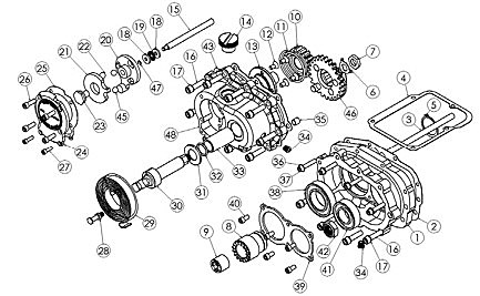
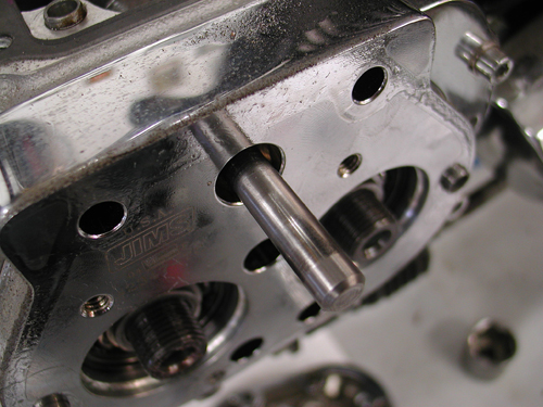
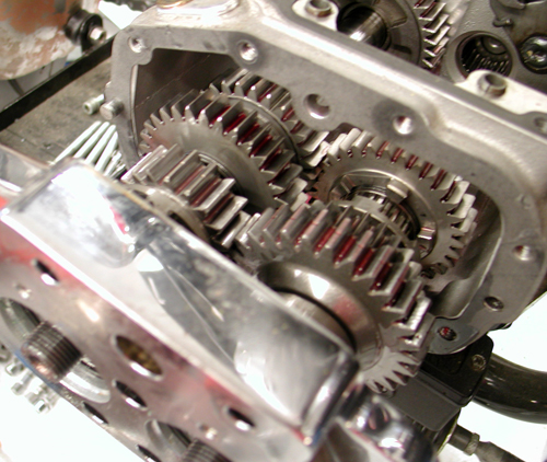
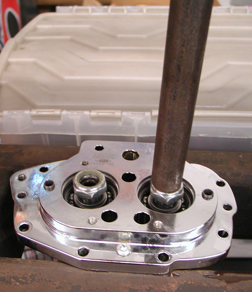
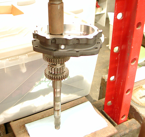
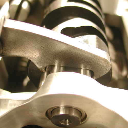
Now take your mainshaft assembly and support it vertically in the press with the clutch end of the mainshaft at the facing down. Insure that the cage bearing is still on the cluster with first gear around it. Now take your Factory 5 Kicker bearing door (PN 1-5SK(P,R,B)) assembly and press the mainshaft into the ratchet hub (PN 308-5) while using the ratchet hub (PN 308-5) as your press point (figure 2).
Make sure your mainshaft is perfectly vertical before pressing it in, damage to threads could incur if not vertical. Remove assembly from press. Apply thread ‘Red’ thread lock to the mainshaft retainer nut (PN RV-7050) and torque to 45-55 ft/lbs.
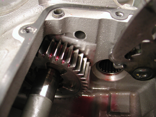
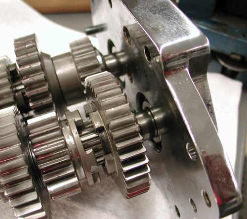
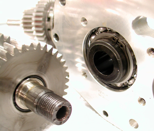
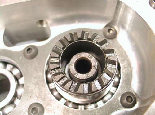
Once the mainshaft is parallel with the countershaft place the countershaft press tool on to the countershaft bearing in the assembly (see picture). Slowly press the countershaft into the bearing door making sure all the gears spin freely. Once the countershaft is seated, clean the threads with lacquer thinner and blow dry completely. Apply ‘Red’ thread lock to the countershaft retainer nut and torque to 45-55 ft/lbs. Your bearing door assembly is complete
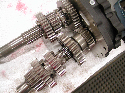
GEARSET INSTALLATION
1.) Refer to your Factory Service Manual for proper gearset installation.
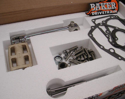
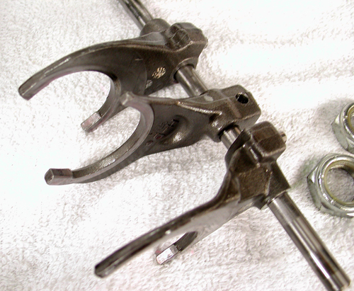
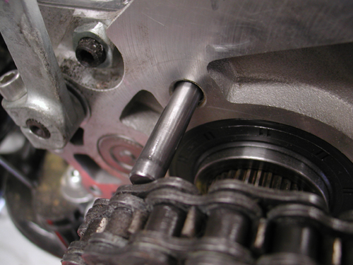
2.) You will need to use the supplied fork rod (PN 122-56K) for installation.
3.) Replace the bearing door assembly with the supplied gasket (PN 35652-79B).
4.) Once the gearset is in the transmission case. Use the four supplied 5/16-18 x 1-1/4 SHCS (PN 73496) and 5/16 washers (PN 6100) in the lower four holes of the bearing door. Using ‘Blue’ thread lock, torque the bolts to 13-16 ft/lbs. Install the four supplied.
¼-20 x 1-1/4 SHCS (PN 73463) and ¼ washers (PN 609SS) in the upper four holes of the bearing door. Using ‘Blue’ thread lock, torque the bolts to 7-9 ft/lbs (84-108 in/lbs)
5.) Install your top cover per your Factory Service Manual using the supplied top cover gasket (PN 34904-86C)
CABLE TYPE KICKER COVER INSTALLATION: PN 578-56M(P,B,R)-K Refer to your Factory Service Manual to remove your clutch cable from your side cover ball and ramp assembly.
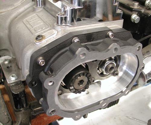
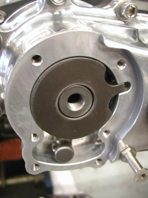
1.) Place the side cover gasket on the two 10mm dowels (PN 16583-00) on the bearing door assembly.
2.) While making sure the ratchet gear (PN 310-56K) is still retained by the kicker crank gear (PN 33350-56), place the side cover on to the two 10mm dowels (PN 16583-00). While holding the cover in place take the nine supplied 5/16-18 x 1 ¼ SHCS (PN 73496) with 5/16washers (PN 6100) and apply ‘blue’ thread lock to the threads. Now torque the fasteners to 13-16 ft/lbs (156-192 in/lbs).
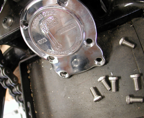
3.) Remove the six fasteners holding the ball and ramp cover on. Remove the ball and ramp cover and gasket at this time as well.
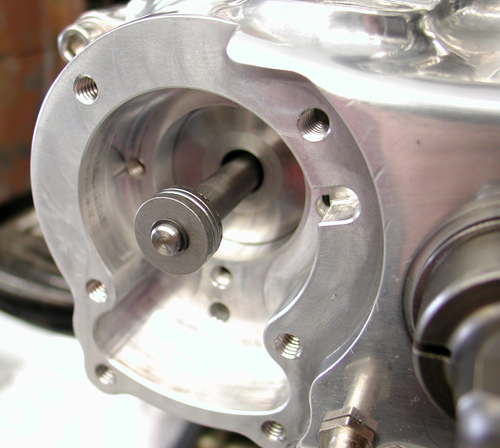
4.) Install the supplied clutch throw out rod (PN 125-5R) at this time through the pinion gear quill (PN 585-5)
5.) Thread your clutch cable into the side cover. Loosen the clutch cable adjustment all the way so there is maximum cable exposed in the side cover.
6.) With the cable fully extended in the side cover take the supplied ball and ramp assembly and slide it over the cable. Install the clutch cable ferrule
9.) Using ‘Blue’ thread lock, install the six bolts. Torque the four ¼-20 x ¾ (PN 25C50KLHS) to 7-9 ft/lbs (84-108 in/lbs). Torque the two #10-24 x 5/8 (PN 10C50KLHS) to 4-5 ft/lbs (54-60 in/lbs).
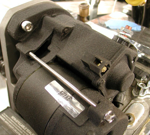
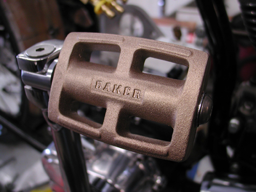
KICK ARM INSTALLATION
1) Install the kick arm on to the kicker crank gear shaft.
2) Tighten the pinch bolt on the kicker crank gear shaft so that there is no sloppy movement in the kicker arm assembly.
3) Either with your hand or leg, ‘kick’ the kick arm and run it through its motion to make sure everything is working properly.
FINAL ASSEMBLY
1.) Install your primary and adjust your clutch per your Factory Service Manual at this time.
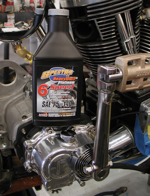
2.) With the bike vertical fill your transmission with the supplied 23oz. bottle of Spectro™ 75W140.
3.) Follow your Factory Service Manual to finish assembly on your motorcycle.
4.) Your BAKER Factory 5 Kicker installation is complete
For any installation or service questions, please contact our BAKER technical department toll free 1-877-640-2004.
Hang on for the next installment. Final assembly will begin with a BDL primary install, a Spyke alternator/regulator system, and we're getting ready to ride.
You'll see George's pinstriping, Tony's powder coating workmanship and my sloppy wiring.
–Bandit