5-Ball Factory Racer Build for 2009-2
By Robin Technologies |

Moving right along, I overcame the Wilmington Mung and slipped back into the shop. It’s like self-induced Christmas for the homebuilder each week when UPS arrives or I score something at the bike swap meet. Ya plan, save small bags of gold and reach out to vendors to make deals, then wait.

I got all pumped when the bronze risers drifted in from DPPB in Europe, and I immediately tackled the mounting and handlebars. I hit two hardware stores looking for the proper length hardened studs and the second score was doubtful, but I rolled the dice and bought them anyway. As it turned out, 3-inch ½-inch studs with coarse threads on one end and fine on the other worked perfectly.
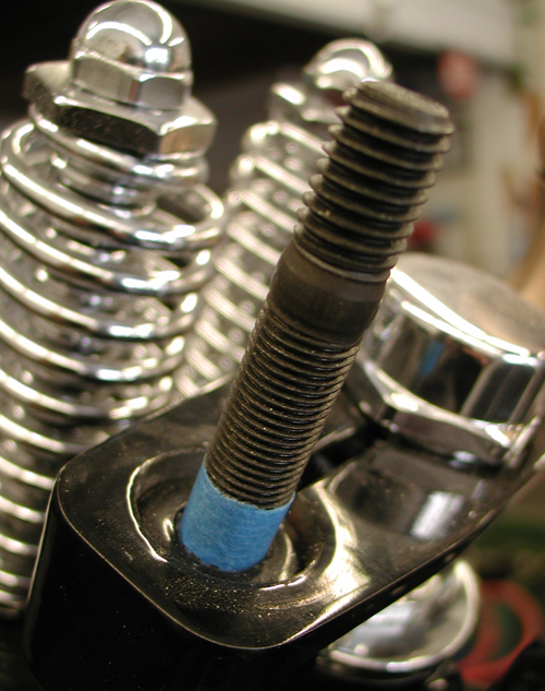
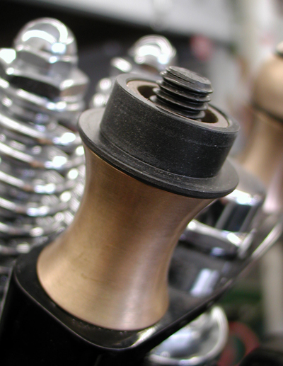
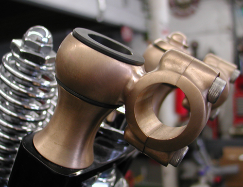
I tested the fitment by wrapping masking tape around the fine end 3/8-inch up from the bottom. I screwed them into the narrow Paughco leg, and then installed the riser components to see if I had enough length to reach the top bronze nut. I had plenty of threads, so I move the tape to 5/8 inches of securing fine threads and installed all the components. It all fit like a dream.
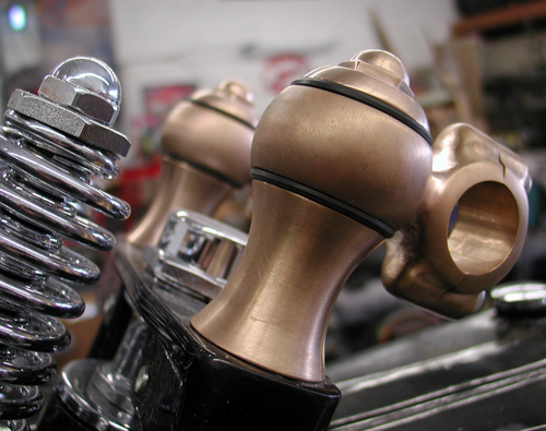
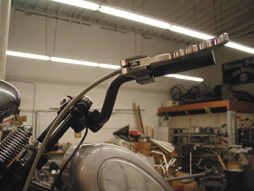
Then I went to work searching the shop for a set of bars that would give me the look and be reasonably comfortable. I’m shooting for that 5-Ball Factory Racer look, but a bike comfortable enough to ride to Sturgis. That’s always the acid test, and the road-test adventure. I found a set of sorta TT 1-inch bars sans the dimples, since I was going to turn them upside down. I mounted them to the risers, and then determined that I could cut almost three inches out of the center.
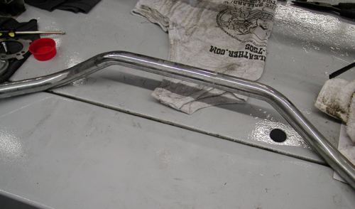
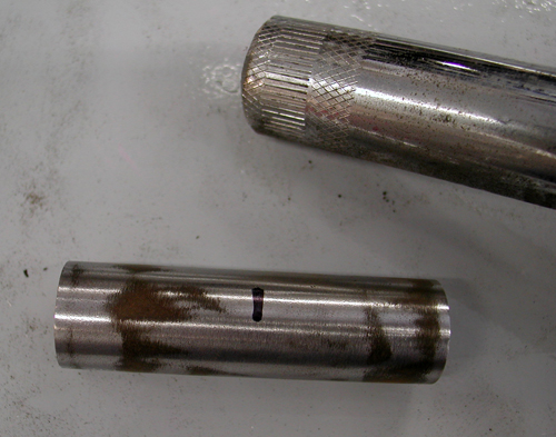
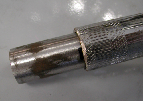
I searched the shop for a chunk of mild steel rod that would make the perfect alignment, strengthening slug for the bars. I removed the burrs from the split tubing and marked the slug center. I tapped it into place, strapped the bars down, so they were perfectly aligned, and MIG-welded them. Just having the bars and risers in place was a rush.
I finally muscled enough cash to have all my welding tanks filled. I took the opportunity to have one tank filled with pure Argon for welding stainless or aluminum. I’ve never welded aluminum, so I broke out my welding book and read the appropriate chapter. I needed twice the gas pressure and almost twice the rod speed and power.
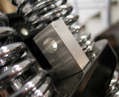

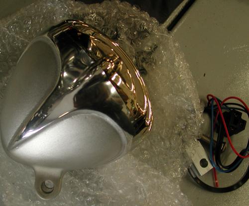
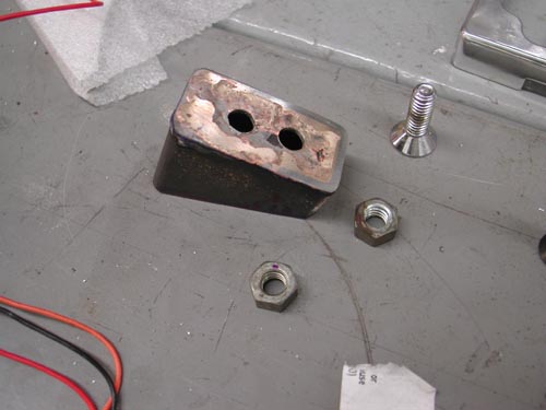
Let me back up for a second. The project was mounting the Crime Scene Rapide headlight. It was a bolt-on procedure, except for the simple aluminum-mounting bung. Once in place, it was impossible to remove the headlight-mounting fastener. I reviewed my options. The fastener would actually touch the top Paughco springs. I looked for an option and found one, but it required welding the existing square bung to the fine-threaded round spacer. I tapped the spacer for clean threads, and then proceeded to weld the two together.
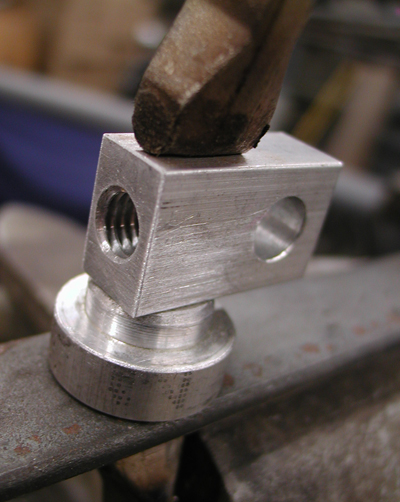


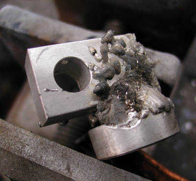
This was a trick. Aluminum must be extremely clean before welding. And since this piece was very small, it could heat up and melt like butter before one pass was completed. I also had some problems with the welder. Since aluminum heats and expands faster that steel, I needed to bore out the tip or run a larger welding tip. The tips come in various sizes, and natch, I didn’t have a slightly larger tip. So Jeremiah grabbed a micrometer and all my tiny drill bits, and started to study the sizes and attempted to drill the tips out. Interesting procedure. We broke bits and jammed them into the bronze MIG welding tips. Finally we succeeded in boring out a tip and the welding moved along.
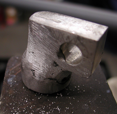
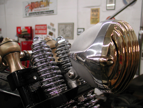
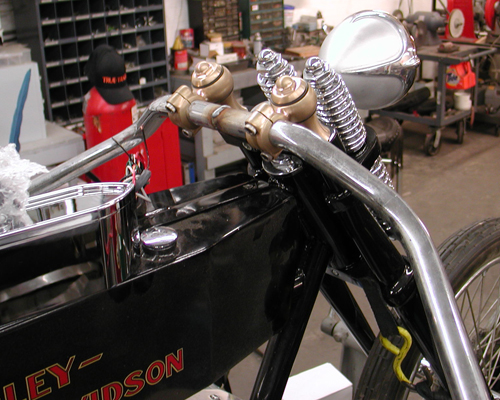
Then I took to grinding, filing, and rewelding until this headlight bracket was completed. Not bad. I need Jeremiah, the master shaper, to return and give it his final touch.
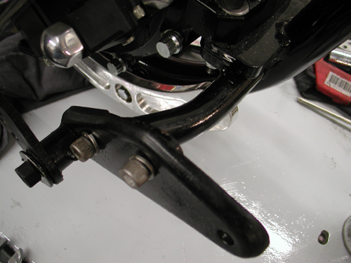
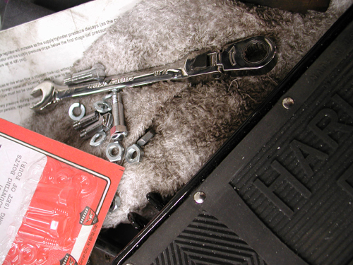
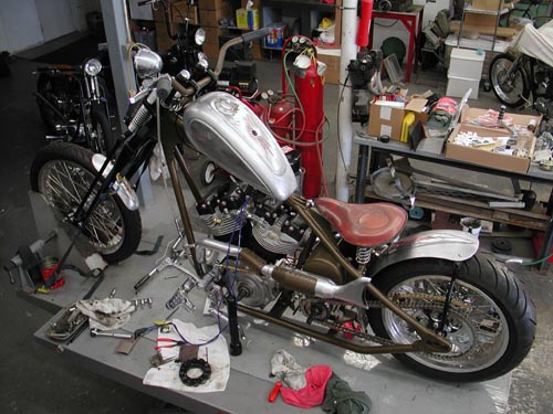
Next, I had a plan to use as many vintage H-D parts as possible. I snatched a stock 1936-1957 mechanical brake pedal and mounting plate, which also acted as the front peg or footboard mount. Paughco already made a bracket that bolts under the front motor mount. It makes the stock mounting bosses available for these components.
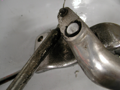
This effort placed me eyeball-to-eyeball with a couple of challenges. I needed to make the old mechanical brake pedal operate a hidden hydraulic master cylinder and somehow I had to create a mounting bracket for the rear of the footboard.
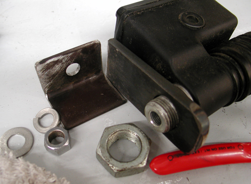
There was one more element rearing its ugly head at this point, but yet we turned it into an opportunity. There was no fifth stud mounting plate on the frame, so I started to tinker with a chunk of angle iron. Then I discovered a complete ’98 Dyna rear brake set-up with linkage and the master cylinder. Suddenly, lots of answers were available using the fifth stud-mounting placement.
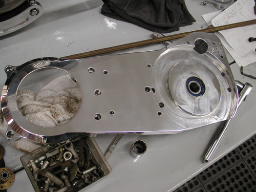
I had to stop dead in my tracks right there. I needed to make sure the transmission was aligned properly for the whole system to work. The brown Santa arrived with a new BDL Softail, 2-inch enclosed belt drive system I’d ordered just a couple of days ago. I pulled out the inner primary, loosened all the mounting bolts for the engine and trans and started my historic alignment procedure. First, I bolted down the rear of the engine and looked for any gaps at the front motor mount. It had a .020 gap. I found a shim and slipped it into place.
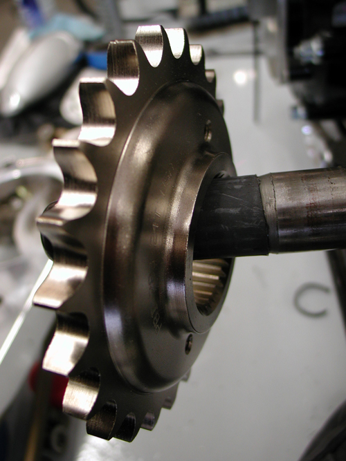
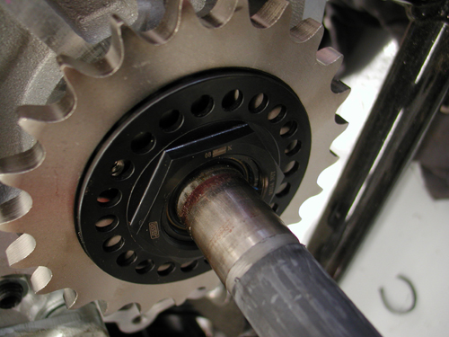
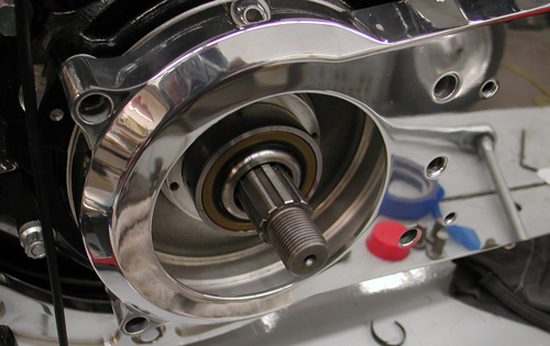
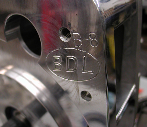
Next, I attached the BDL inner primary and pulled the JIMS tranny into alignment with the Crazy Horse V-Plus engine. Then I started on the fifth tranny stud-mounting bracket. I planned to run a kicker, and since this power plant is 100 inches strong, the additional mounting element will strengthen the entire driveline.
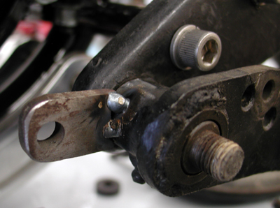


No, this system didn’t fall into place. I had oil lines to contend with and the brake pedal and master cylinder didn’t align. At first, I had a grand plan to bend the linkage rod into a jog-over to reach the tab I had welded onto the brake pedal pivot tube. That would have created more problems, specifically with the rear footboard mounting. I needed to straighten it out and machine a 2-inch offset link from the pedal over, which kept the entire system in alignment. The critical aspect will be my tab welding. There will be considerable strain on that puppy, but I think it will work.
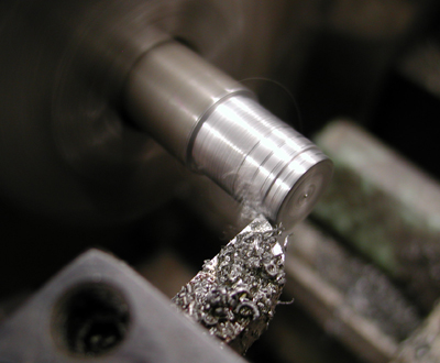
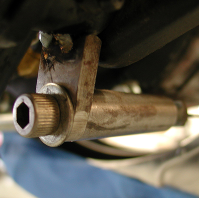
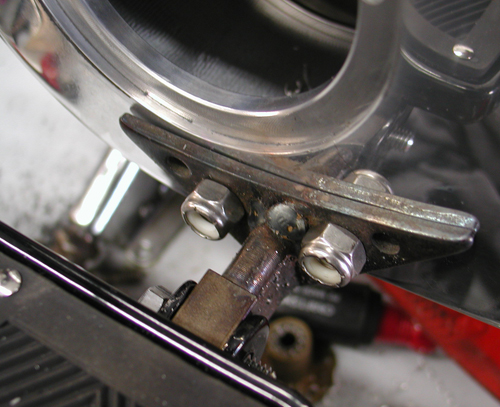
Then I ran a ½-inch rod off the top of the pedal bracket and machined a spacer that would catch an original classic footboard-mounting arm. I’m trying to tack-weld everything so I can make final adjustments or catch mistakes before it’s too late. I like welding and sometimes can’t stop myself. I tack my handiwork, step back, eyeball it, check it twice and weld the shit outta it. The next morning I discover something I forgot and I’m fucked.
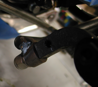
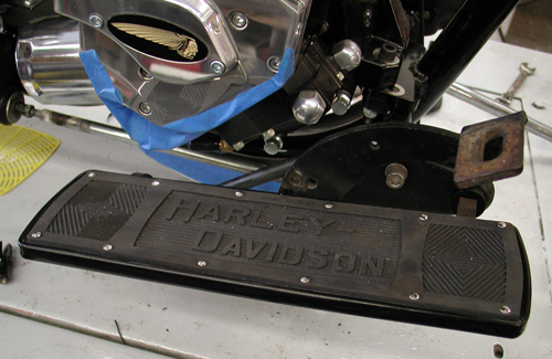
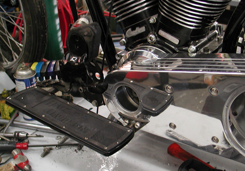
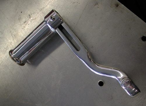
Since I was into footboards, I moved onto the left one. With the help of Sin Wu on her knees, we checked the angle of my 2003 Road King footboards and attempted to match that angle on the 5-Ball Factory Racer. Again, I used a stock mounting plate with foot clutch pedals. I’m going to make the racer a tank shift, so I bolted up the mounting plate and a vintage kicker arm and bracket, but I needed to drill and tap the Paughco bracket for the lower left 5/16 kickstand mount.
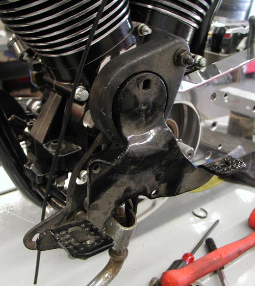
I tried to handle a few moves at once and failed. I broke off the tape in the kickstand mounting hole and I’m still pondering my options. I shifted back to floorboard mounting. I was burnin’ daylight trying to remove the tap. I mounted the front of the footboard and snugged it down at the Sin Wu estimated floorboard angle, then pondered how to mount the rear to the BDL outer primary.
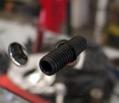
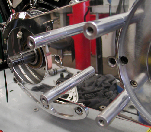
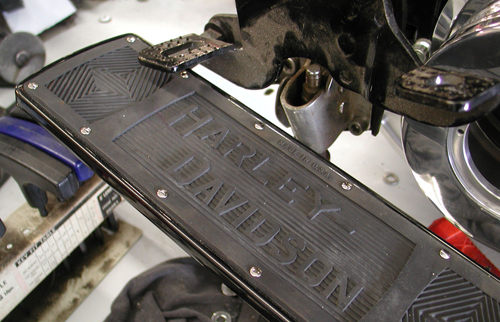
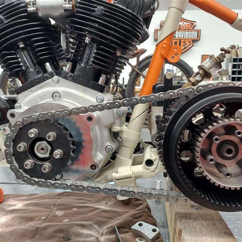
I had to insert the BDL mounting studs into the inner primary with red Loctite first, then the aluminum stud arms, and finally the cool, clean outer primary cover. This turned out to be a breeze. I took a vintage footboard mount, cut it off, and welded it to a Bandit-made bracket. It had to carry my weight, so I added a strengthening gusset to the bottom and believed I was good to go.
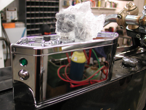
In the next segment, we will start to tackle the shift linkage system. Duane Ballard’s wife, Lisa, a contributor for the Cycle Source magazine, delivered this vintage tractor seat assembly for us to test and you’ll see our wacky test next issue. We might also start to tackle mounting the Paughco/U.S. Choppers tanks, Phil’s Shop wiring system and the Biker’s Choice Speedometer, which we hope to mount in the tradition of rear-wheel driven speedometers of the ’20s.
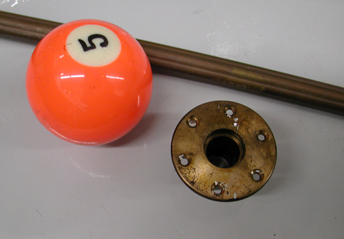
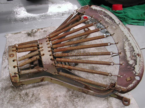
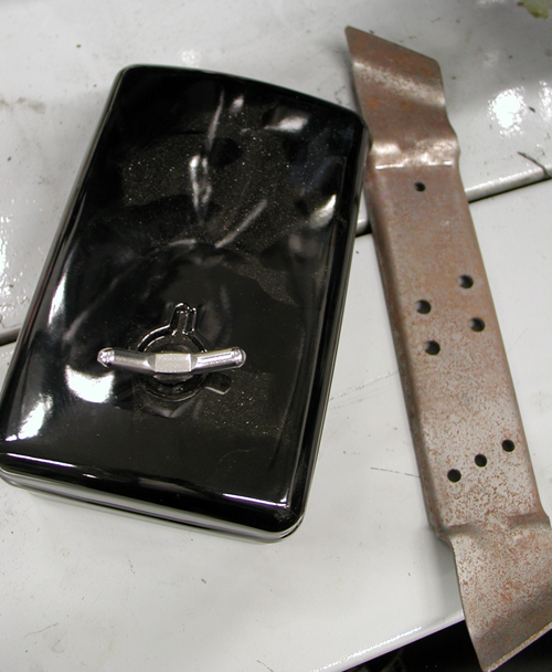
It’s all headed your way in the next couple of weeks.

Mudflap Girl Part 1a
By Robin Technologies |

Back to Mudflap_Girl_Part_1_the_Concept
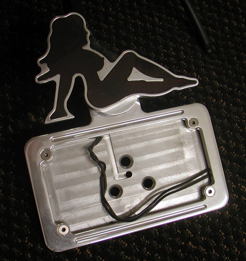
So we’ve collected a handful of mudflap girl products from Billy Lane, at Choppers Inc. , 2-wheelers in Denver, Sturgis and Daytona and Nick from New York City Choppers. Then we needed a fitting bike project, and one surfaced. Seems a Bikernet babe grew up in the San Pedro projects with eight brothers and sisters. The oldest one, and most supportive, hardest working, was Brad Olsen, a longshoreman crane operator in the LA Harbor.
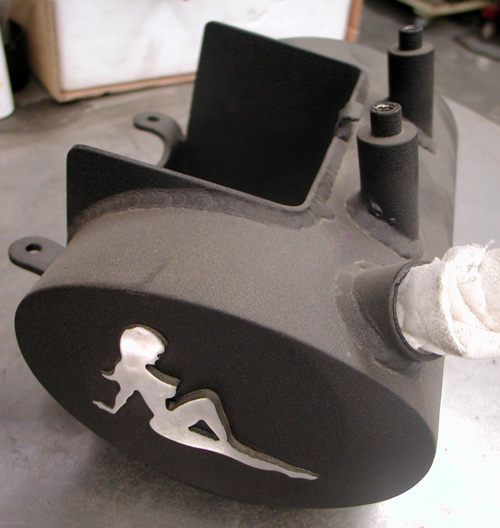
Those kids grew up on the tough side of the harbor and Brad took the brunt of the hard life, became a fighter and family member defender. He worked the ports, went to school, became a tugboat captain and ultimately, a crane mechanic. For eight years he trained under Richard Bustillo, who worked with Bruce Lee, and Brad became a master and owner of his own dojo, Harbor Kick-Boxing in San Pedro.

Brad fought for his brothers and sisters, and then worked with inner-city kids to build their self-defense abilities and self esteem. Brad has owned a 1961 Panhead for 25 years and keeps it pristine. It’s his baby, but his kicking knee is damaged and he needs a long-distance touring bike with an electric starter. That’s where the mudflap girl came into play.
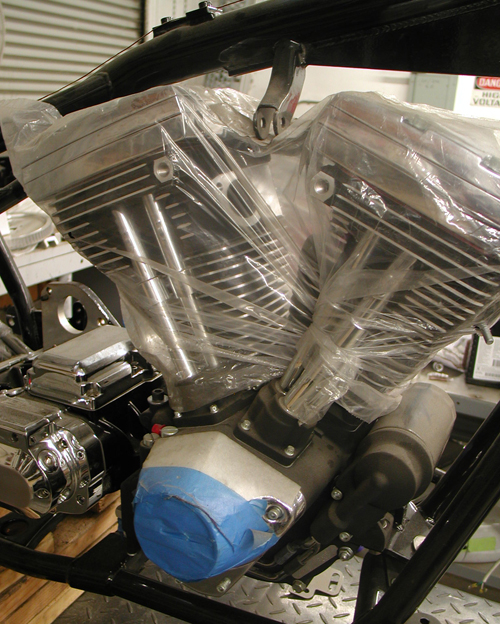
The project started with a salvaged 1998 Dyna Glide basket, which we tore apart. We sent the engine to Harley-Davidson for a re-man effort with the help of Fullerton, California H-D. The transmission was rough and we wanted a 6-speed for those long Mudflap Girl highways. I had a JIMS 6-speed, which I returned to the JIMS factory. We switched and twisted the Dyna Glide 5-speed transmission into a JIMS FXR, 6-speed and a Softail 5-Speed for another project (my 1915 5-Ball Factory Racer).
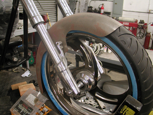
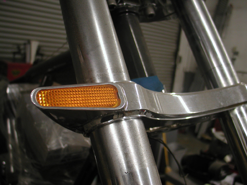
I’m not a big Dyna, fan so we dug out my last Quantum, Kenny Boyce styled Pro Street FXR frame and went to work finding parts. I bought a used Arlen Ness FXR swingarm from LA Chop Rods and dug out a wide Custom Chrome inverted front end with turn signals built in. The overall design element called for building a tough and reliable touring motorcycle for Brad.
Another key element for the overall package was the bags we ordered from Redneck Engineering. Once we had a set of Renegade Wheels like we used on the Assalt Weapan, mounted to new Cobra Avon Tires we were ready to begin the mock-up stage.
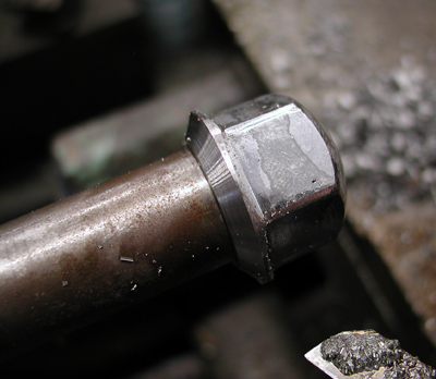
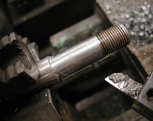
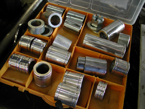
Of course, I used Doherty Machine wheel spacers to center the wheels and had to machine a stock axle to fit the Custom Chrome wide glide.
Handling is an issue with any rubber-mounted bike and we pressed in Custom Cycle Engineering swingarm bushings to tighten the ride. Plus I’m still trying to work with a tougher swingarm axle from www.Glide-Pro.com.
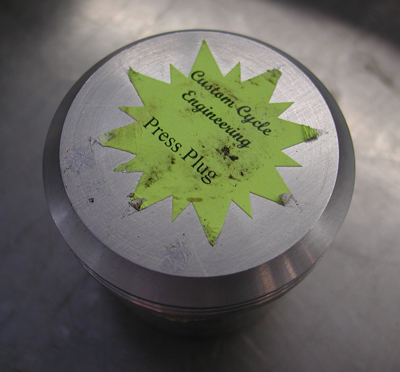
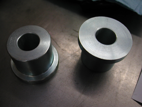
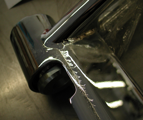
I spoke to a couple of builders about installing the driveline in a FXR frame and some bolt the engine and trans together, then lay them on their sides. They slip the frame over the top and install the swingarm, swingarm axle, rubber-mount biscuits and transmission to the frame. Unfortunately, I don’t care for that system. It’s against the Code of the West to lay a Harley engine on its side on the ground. Bad mojo.



We mounted the front end and front wheel to the frame, then put a jack under the frame. Then we mounted the swingarm and transmission together in the frame with the axle. Next we installed the Renegade wheel. I moved the jack. with a chunk of wood to lift the transmission until it was level.
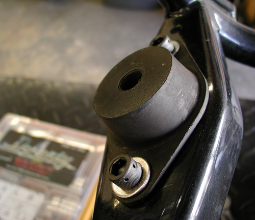
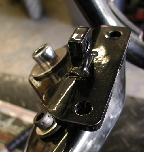
Then came the Quantum front motor mount, which was offset. We may replace it with a stock touring mount. Here’s what Rogue had to say about it:
No, they are not specific to the frames you have. They can be used with anyrubber-mount FXR frame to offset the engine 3/8ths of an inch to the left.We originally used them with the frames Kenny Boyce made for Quantum.
Looking back over some old paperwork it appears you got two blackpowder-coated Quantum frames that were made for Quantum by Kenny Boyce.
These frames were used with the front offset mounts and had the transmissiontail shaft modified by removing 3/8ths of an inch from the left side and useda spacer of the same size on the right. This moved the engine andtransmission equally to the left.
Later, Quantum used a set of offset rear swingarm end caps as opposed tomodifying the transmission. If a stock front motormount was used, no changes had to be made to the rear.
My notes say you also got a bare Quantum frame made for them by Kraftech. The mounts were usually used when using a fat tire on the rear.I had a bunch of them and figured you could use them for something. You donot have to use them!
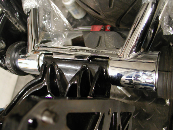
I was confused by the offset, so it’s always a smart notion to check with someone who knows. Rogue worked for Quantum back in the day. We will eliminate the offset front motormount plate as we roll forward.
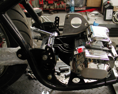
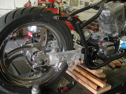
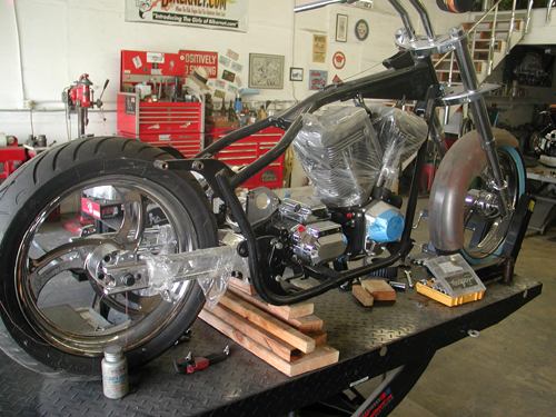
With the trans jacked level and the front rubber pad mounted loose with the front engine plate, mentioned above, snugged to the biscuit with a ½-inch bolt, we dropped the engine into place, like we would in a rigid or Softail frame.
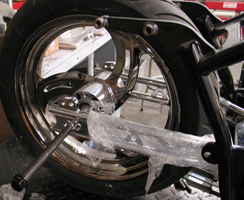
Next, we’ll replace that front motormount, shave off the existing tank mounts, start to mount a Custom Chrome gas tank and rear fender and prepare Redneck Engineering bag mounting brackets.
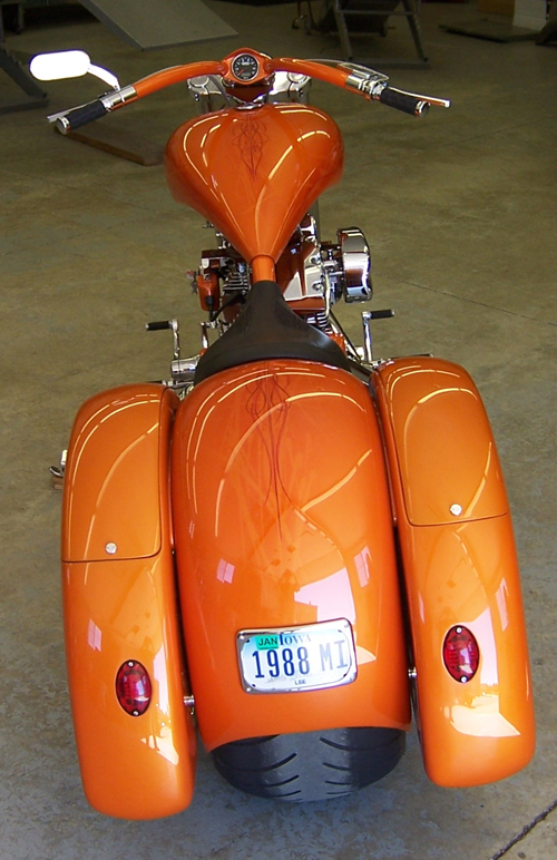
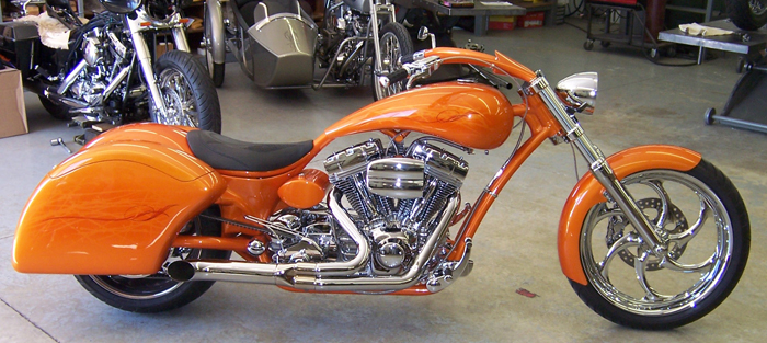
Above is a bike built by Don Hotop for his wife using Redneck Engineering bags. The fiberglass bags are designed, and come with mounting rails for Softails. We will need to cut the bags for Progressive Suspension shocks and build very sturdy basketry.
Click here for: Mudflap Girl Part 2, the Bandit Engine and Spitfire update

Sturgis Shovel Part 13
By Robin Technologies |

Hang on. This is the last of the scintillating segments on building the Sturgis Shovel before I write the treacherous saga of the ride. Somewhere we will publish a feature on the bike in a mag and on the site. Oh, there’s one other tech that will come to pass—hard line assembly. I’m waiting for a CD of images from John Gilbert of Bike Works mag.
So let’s get started. I was burnin’ daylight before the Sturgis run. I saved a ton of cash going with all powder and no additional chrome or polishing. It cost me just $325 to powder all my components for lasting protection.
Throughout this article I will point out my mistakes, so you can avoid them. I did an 80 percent decent job of mocking up the bike prior to powder. That meant that 20 percent had to be dealt with after the finish was applied. Bad news. The only thing I didn’t think through or make brackets for was the ignition switch and circuit breaker brackets. That may seem minor, but wasn’t as you will discover. On the other hand it wasn’t a big deal. You be the judge. Actually, if we wired, fired and rode the bike before final teardown, it would answer all the questions. But few builders take it that far.

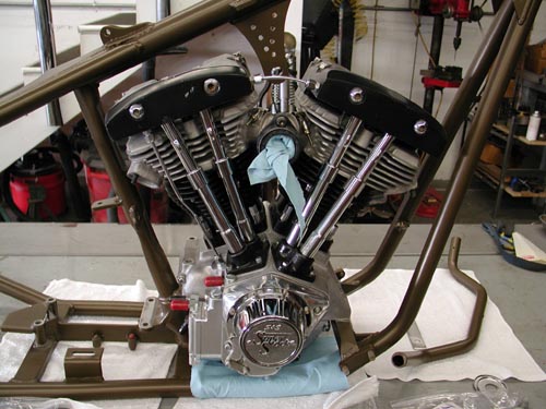
I was jazzed to toss the Paughco Frame on the lift covered with pads. Foremost Powder had plugged all the threaded holes and tapped off the neck bearing surfaces. They did a helluva job. I shaved motor and transmission mounts for a proper ground and installed the S&S modified 93-inch engine and JIMS trans. Then I could install the Paughco Springer without a balancing act.
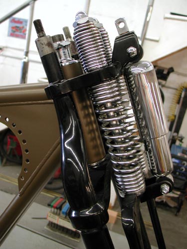
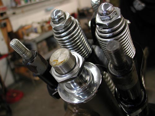
The Springer is easy to install, but takes care. I greased the bearings, slid on the dust shields and ran the whole springer through the neck. Keep in mind that installing the bearing races in the neck is not complete until the bike has been down the road. Any paint, dust or uneven race angle will mean that the bearings will seat further once on the road. Ride it for a week then lift the front end off the ground and jiggle the wheel by the axle. If there’s any movement or dangerous slop, take the bars and top tree off once more and tighten the stem nut until there’s just a hair of drag. Long front ends are more critical because of the leverage against the neck.
I didn’t bolt down the engine and trans hard, just the tranny plate which ultimately I had to loosen. The engine needs to be completely at ease for the BDL belt alignment so I just spun some stainless bolts into place. Then I installed the front wheel with Doherty spacers, the Brembo brake caliber and centered the wheel. Keep in mind that Brembo supplied the bracket, which is designed to replace a stock, late-model Harley springer brake system. I didn’t have the proper spacer, but a Harley shop had one and I was good to go.
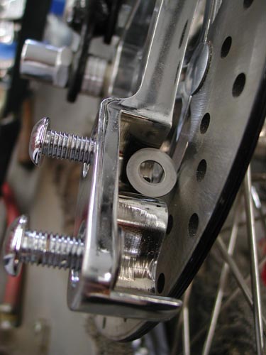
Then I installed the Brembo Caliper. They supplied me with a series of shims. I used feeler gauges to determine centering the caliper over the rotor and stacked the shims until it was set. This is an interesting bumbling, experienced manner for writing articles. I have the insight of riding experience behind images of the bike yet complete. Ultimately we removed the front fender.
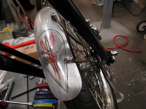
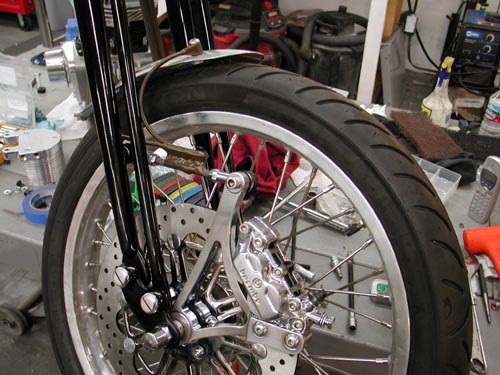
I build the front fender, single sided bracket after Kent’s, from Lucky Devils Metal Works in Houston, caliper mounted fender mounts, which work perfectly. My problem was the initial position of the caliper, too far forward. So I mounted it on the heim joint rod which didn’t work. When the bike went over a bump the front lip of the fender rode up with the caliper and the rear lip rode down with the springer touching the tire. It had to go. So I rode to Sturgis without a front fender ducking rainstorms all the way.
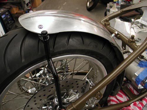
Next I installed the rear fender. Keep in mind that the rear fender, the oil tank and the rear wheel fight for the same spaces. They almost need to go together simultaneously, especially the oil bag and rear fender. Everything slipped into place with nyloc nuts, stainless Allens and red Loctite.
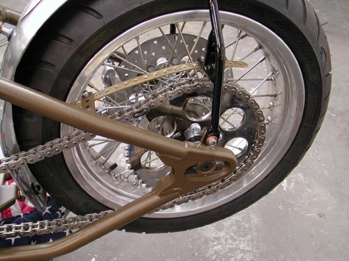
At the time I ran stock gearing with the JIMS 6-speed, until I discovered that I was faced with running a kicker. I didn’t change the rear wheel gearing from the 51-tooth, but I should have. This evening I’ll install a Custom Chrome flat (Sportster styled) 48-tooth sprocket and hope to knock the revs down seriously.

I also mounted the rear Brembo brakes and centered the caliper over the Brembo rotor. No problem. Even my Softail styled anchor bracket worked perfectly welded to the frame and tucked the caliper between the frame rails.
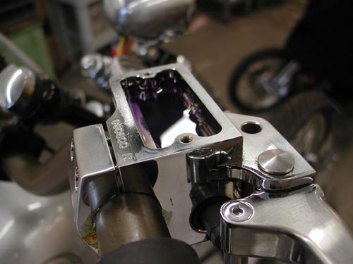
While I’m messing with brakes I’ll cover brake and clutch lines and cables. Instead of making up lines I ordered RevTech pre-assembled lines from Custom Chrome plus all the fittings washers and fasteners. Keep in mind that the front brake master cylinder uses larger master cylinder banjo bolts. They come in 10mm and 12mm. Watch out, and don’t hesitate to order a couple of extra bangos bent at different angles to make sure you’ll have what you need.

I measured my lines and clutch cable lengths a number of times then added an inch for safety. That’s where making your own lines can be helpful. Keep in mind that the front end will turn (clutch cable) and depress (front brake). You’ll need some slack. Plus you might change the angle of your handlebar levers, which will impact the position of the cables and lines. I used Tephlon tape on most fittings although some builders don’t recommend it. Since most of this stuff is chromed, I like the extra sealant.
I use only DOT 5 brake fluid in my bikes, ‘cause I can splash the shit all over the place without concern for paint damage. In many instances you can fill the master cylinder and rock, just by waiting for the bubbles to rise. Another key is to find the right pump can and fill the lines, caliper and master cylinder from the bottom up. Use a new pumper or a pump that’s dedicated to brake fluid only and attach it to your brake bleeder on the front wheel. Most of the time that works like a charm.

I’ve found that most front brakes will basically bleed themselves. Fill the master cylinder on the bars and pump it slowly allowing the bubbles to rise. Let it set overnight and most of the bubbles will rise just by pumping it with short strokes at the lever and watching the bubbles jump to the surface.
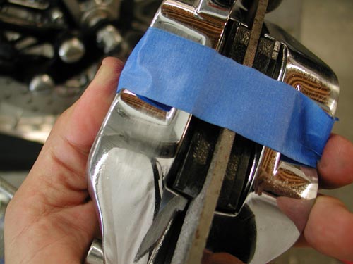
In this case I discovered that some air was trapped in the caliper, so I pulled it off the bike, taped a file (the same width of the Brembo rotor) and turned the caliper so the air could escape through the bleeder nipple. I bleed it a couple of times then returned the caliper to its rightful position. She was good to go.
The rear brake wasn’t so easy because the air couldn’t rise to the master cylinder. I bleed it from the front and the rear, and I think it still has air in the lines although the Brembo brakes worked fine. I received a lot of compliments and comments on the brakes, which I found strange. Brembo has a terrific reputation, but not on Harleys. Riders were surprised to find Brembos on a Chopper.
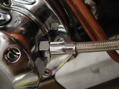
Now for the clutch cable. First I was confused about which cable style to order. I hope to put together an article on it in the near future. I picked the most common late model Evo cable and measured the length several times. Here’s the key. If you’re not replacing a stock cable you have no notion of the length. I pulled a stock cable and measured it, but I didn’t know what model it came from. I went by the length of my stock cable and found the 1990-1999 Fatboy cable length. Then I measured the extension due to the Paughco Frame, CCE risers and CCI bars. Much guess work. If I had all the bucks in the world I would have bought three cables lengths.
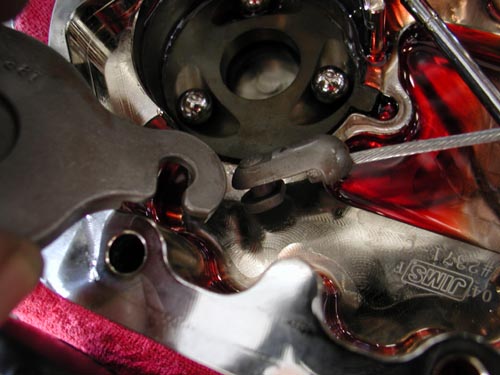
The end cap cable is the reason Baker, JIMS and RevTech transmissions come with a fresh gasket and a quart of transmission oil. They know that you’ll be forced to pull the end cap to install the cable in the ball driven throw-out bearing mechanism. It’s simple but cumbersome. Don’t loose the balls. You’ll need a massive C-clamp removal tool to pop that sucker free. Carefully lift the inner ramp and remove the cable coupling, attach the cable, which you have already screwed into the trans face cover. Return the coupling to the inner ramp by watching the puzzle face. Then put the ramp back in place and the retaining ring and bolt the face cover back into place. Don’t forget to add at least 20 ounces of Trans fluid. It will hold 24 ounces dry.
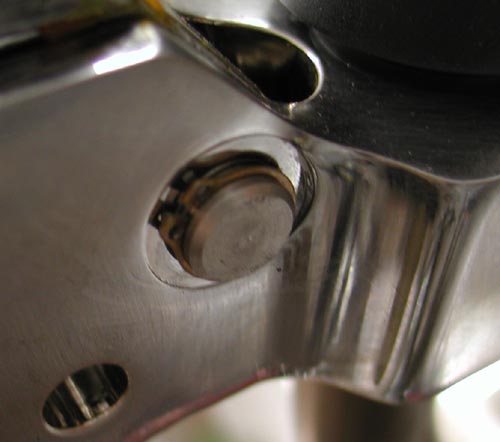
I learned something on this trip. If water gets in the trans it will act up, shift strangely. Drain the fluid and change it. Check your vent.
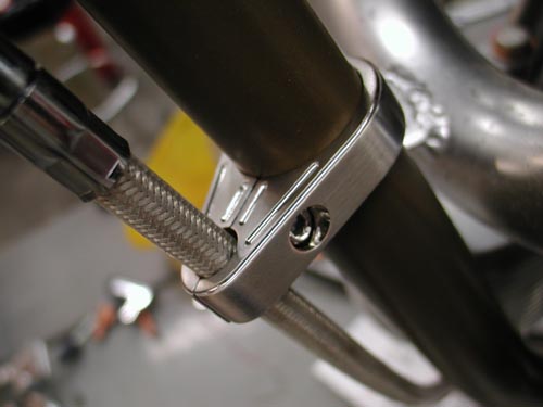
I ran the cable several ways to find the path that fit best, didn’t rub the frame or catch on anything. I used one Arlen Ness cable clamp to secure it and hooked the cable into the greased tephlon bushing in the Joker Machine handlebar control, then replaced the small C-clamp and I was ready for final clutch cable adjustment after the BDL primer was installed.


I’m going to cover the 300 BDL installation here and try to explain my shift. My plan was to run the Compu-Fire engine based electric starter system designed by Giggie before he left and took a job at Rivera. Rivera is making inner primary plates for this new system, but when I contacted them Ben Kudon’s response was hesitant. They weren’t ready. Of course I contacted our long-time sponsor BDL and initially they weren’t scheduled to make units, then I was pleased to find out they were, so I ordered one. But Sturgis crept into the picture, and suddenly I was without a starting system and coils hanging under the oil bag interfering with any new starter install.
I had a 300 BDL belt system and a starter but no place to put it. Kent from Lucky Devil shrugged his shoulders and said, “Why don’t you run a kicker?”
Sinwu ripped off her top, jiggled her tits and said, “You have one from Muller in Germany.
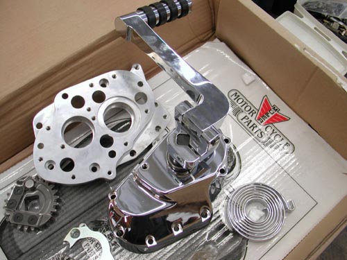
I jammed down the headquarter stairs to the shop and tore open the box. I was jazzed. This is one of the coolest kicker systems to come along. It cleared the rear exhaust pipe and the kicker arm was stylish, unique and strong. I couldn’t believe my luck.
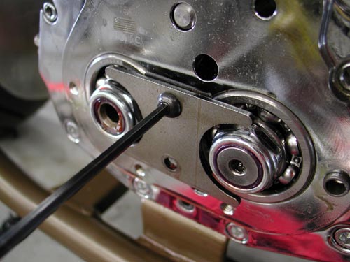
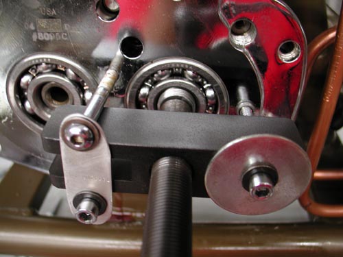
The JIMS 6-speed lined up with the BDL inner primary like a dream. All I needed was to pull the tranny face and press off the trap door, then replace the trap door and tranny cover with the Muller system. Muller even shipped a clutch ramp system that afforded smoother clutch action.
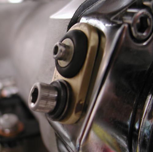
Hell, I’d even build a cool brass plug to cover the speedo-cable hole in the side of the JIMS trap door.
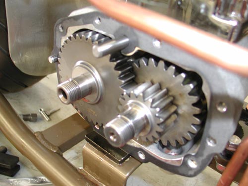
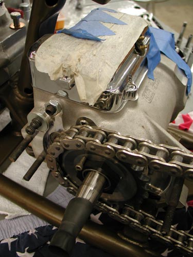
All went well until I removed the JIMS trap door to discover the 6-speed protruding gears. The door was machined to accept the gears and the 5-speed door was not. I was stuck. I contacted Muller in Germany for a 6-speed replacement door. No answer. I called JIMS and ordered the kicker they distribute for the 6-speed. It never arrived, so I called Custom Chrome. If I could order a 5-speed quick, I could use the Muller system. They responded and in three days I had a Rev Tech Replacement complete with kicker and 23-tooth chain sprocket. I yanked the 6-speed and began to install the Rev Tech 5-speed in 4-speed case with a five-year or 50,000 mile warranty.
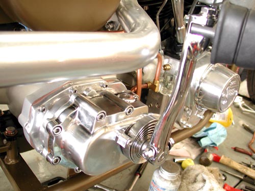
At this point I should have replaced the rear 51-tooth sprocket with a 48 or perhaps a 46, but we’ll see. I removed the kicker cover and installed the clutch cable once more, sealed the tranny and filled it with 24 ounces of fluid.
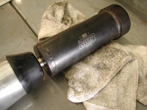
I pulled the massive, left-handed, mainshaft sprocket nut with a JIMS special tool and flopped it around backwards to afford me the clearance I needed for the RevTech chain to pass the 180 Avon tire. I locked it down with the JIMS tool and an Allen setscrew and red Loctite. She was good to go.
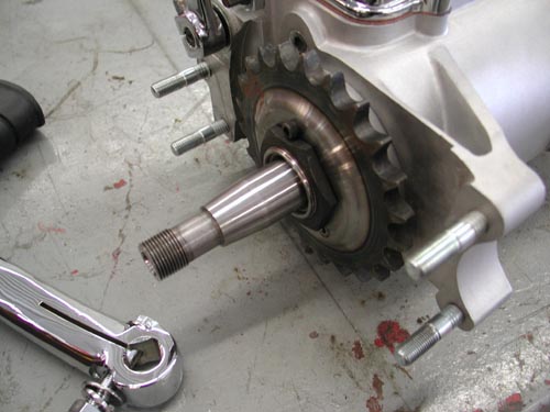
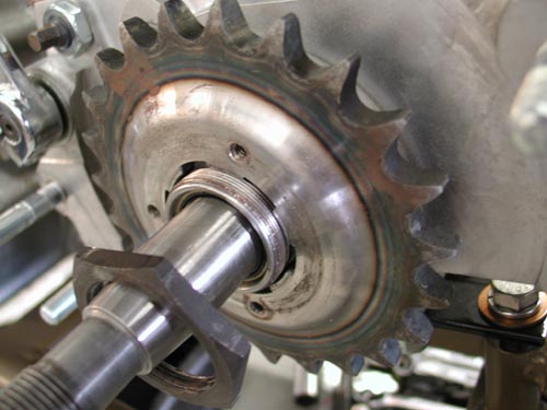

Next, I needed to set up the BDL 300 belt drive system and the Compu-Fire Charging system. I slipped in the Stator, then the small tapered washer, followed by the Compu-Fire Rotor. It’s pasted right on the rotor not to smack it with any hammers. You might knock one of the magnets loose.

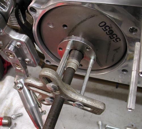
According to the rules sometimes the offset pulley mount doesn’t need the massive flat washer/spacer for proper alignment. But the first move includes installing the inner primary with the engine and tranny loose. I used never-cease on the threads of the transmission and tranny Allens to prevent damage to the threads. Take it back—first I had to remove the inner primary studs from the transmission. They were tight as hell and I used Yield and heat to set them free. Then I positioned the engine and the Trans with the primary.
I ran into problems. Nothing wanted to line up. I called a couple of buddies for guidance. I held the engine where it was with a shim under the front motor mount. Then I bolted the primary to the engine and trans. The front of the tranny raised almost .100. I started looking for shims. Bob from BDL told me the code was to shim the tranny plate and not the tranny, so I went to work. It wasn’t a problem to scour around for the right thickness washers. Soon the transmission was aligned, the primary fit easily and there was no drag on the transmission mainshaft.
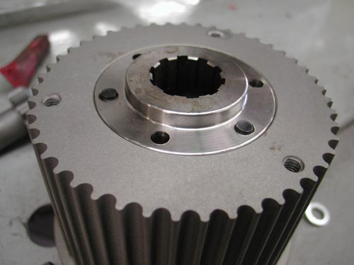
Next, I needed to check the pulley alignment. I installed the pulley using the insert then the pulley and Allens. Since I would be removing and replacing the parts, I didn’t drive the alignment pins into the insert from the rear just yet. I discovered another glitch. I needed some washers or shims behind the engine pulley for alignment. I also discovered that the mainshaft nut wasn’t bottoming out, so the rotor flopped around. That wasn’t right.

I’ve installed a dozen BDL systems without major alignment problems. It takes patience, but once it’s correct, she will last and last. This is a tapered shaft transmission and once it’s installed it doesn’t slip off without a JIMS transmission hub puller tool.
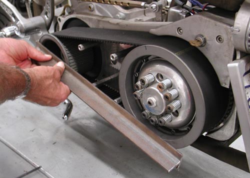
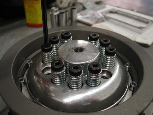
With the pulley and the clutch in place you can test alignment a couple of ways. I used a cast T-Bar across the faces of the pulleys. They need to be exact, which means shims behind the engine pulley.

I made a mad dash to Walkers Machine and bought all the goddamn shims he had. The massive washer that comes with the rotor was only .035 too large. The next item was the inset in the engine shaft nut. I had to machine it to slip over the protruding shaft. This is also an area that takes some running and retesting to make sure it doesn’t seat and settle in, out of alignment. It’s easy to spot a problem. You’ll notice rubber dust around the pulley where it’s riding against the lip.
Remember that the clutch nut is also left-handed. Then the clutch slips into place and with some tugs and working the belt gently, it goes on. If not use two chunks of wood a large bolt and a socket to gently push the pulleys apart. Once it’s run for a while it will be much easier to remove and replace.
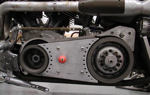

Okay, so I installed the tank, with the Spyke petcock and stripped the spigot threads. It hung for most of the ride. We’ll cover the tank more in the ride saga, so hold on. The seat was also a challenge. I slipped off, so I changed the seat, to one with a lip, then changed it back an added taller springs. That worked.
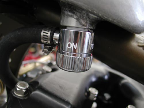
With the primary aligned I still used never-cease on the primary threads because I knew that I would remove the inner primary once more.

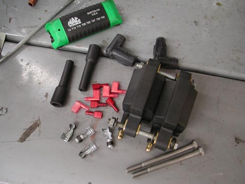
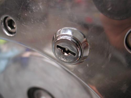
Hang on for this one. I needed to find a place for a toggle switch/ignition switch. I also had this massive aluminum starter motor boss on the inner primary that was going to waste. So I drilled out the starter shaft and installed a marine ignition switch. I glued it in place with a two stage epoxy then drowned it with liquid electrical tape, two coats. It seemed perfect except that the key sang in the wind only 1 inch above the peeling primary belt. No key rings or dice.
On the inside of the primary I made a brass strap that ran from one starter mounting hole to the other, holding two circuit breakers. One was a 15 amp for the lights and a 30 amp for the ignition. This became a very tight electrical area, dangerously close to the whirling CCI O-ring chain. As it turned out the circuit breakers were a hair or two from the coils. Cozy. I made a couple of wires long enough so that I could remove the primary and set it next to the bike to work on wiring issues.

The next thing I knew, under initial testing, the whipping chain chipped at the aluminum, dangerously close to the electrical. Larry Settle, of Settle MC Works loaned me a chunk of tephlon, which I carved and made a buffer, which worked perfectly to protect the chain from nearing hot wires.
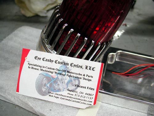
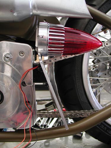
Then came the Eye Candy Custom Cycles ’59 Cadillac taillight. They also make an old Ford style light, which I prefer, but I felt the need for side visibility, especially on the right. The mounting called for the primary once more to hold the taillight/brake light. Finding the proper location was a chore. It either rode too close to the chain or the mounting called for screws through the frame or into the wiring loom. I monkeyed with it for hours and finally designed a tough mounting system that might survive. All went well, but the frame rail still blocks the light and I might move it outbound.
I ran the thin sparkplug wires through the frame in shrink tubing, wired the coil and the Joker machine brake switch and headlight through the hole in the frame too close to the fork stop. Even on a simple chopper an idiot can find his way into trouble.
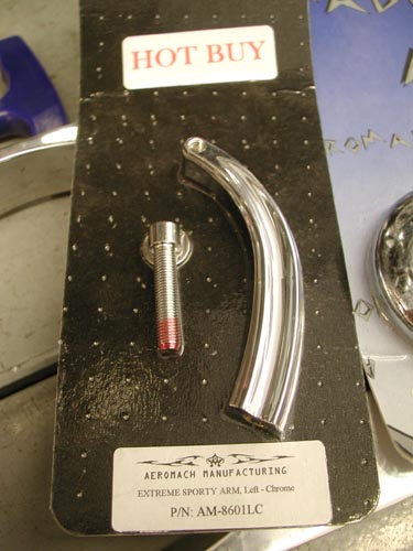
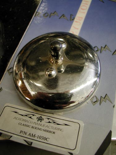
Finally I mounted the stylish Aeromach mirror on the left bar only. It came with all the hardware needed and never gave me a problem. I know I’m missing a link or two, maybe a necessary credit. Don’t hesitate to drop me a line if you need a question answered. You can reach me daily at Your Shots or drop a line to Bandit@Bikernet.com.
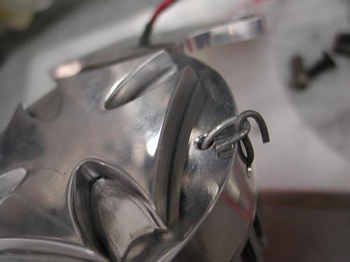
Over the next couple of days I will attempt to complete the first saga of the ride to Sturgis. I hope to launch it on Friday. In it I will dig into the problems I encountered, mistakes I made and how I fixed them. Hang On. But beyond the glitches, actually the wiring worked out fine, but I should wire in a kill switch. The bike rode well, comfortable for a rigid, started without major hassle and ran all the way to Deadwood. I can’t complain.


5-Ball Factory Racer Build for 2009-1
By Bandit |

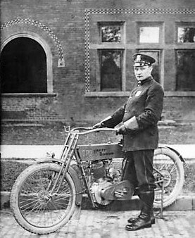
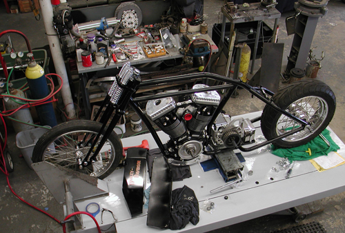
Hey, it's the start of the official Sturgis 2009 project bike, the 5-Ball Factory Racer. For decades guys have built vintage- looking scooters with late model drive-trains. Hell, I built another one at Strokers Dallas in the '90s. Before I dreamed of it, Arlen Ness built a '20s vintage scooter and sidecar around a Sportster engine. Randy Simpson built vintage kit bikes. Don Hotop built some of the finest vintage-styled customs and just last week, I saw a '20s styled bike at the SEMA show in Las Vegas built by the Shadley Brothers for House of Kolors. Beautiful piece. So I ain't the first by a long shot.
But there is something in the air recently respecting the old iron and bringing it back to life. Some of it has to do with restrictions, and building older bikes is unrestricted. Some of it has to do with nostalgia and some is just a wild departure from the last project. I'm excited every year about this learning process. It's like painting one picture on a massive canvas, finishing it successfully, and then pondering the next easel. I get pumped and begin to research what's available.
Billy Lane inspired me with his recent Henderson four custom and his notion to find vintage engines and build bikes around them. We traded a 1913 Pope engine for a '20s H-D Peashooter single that I will ultimately build a Salt Flats racer out of with the help of Todd's Cycle. Dennis is working on the frame and tank.

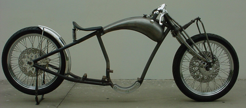
Rick Krost has also been inspirational with his board track racer frame and chassis kit. He was having a tough time finding a manufacturer for his intricate frames, so we drove to Carson City, Nevada and I introduced him to the chopper original, Ron Paugh from Paughco. Paughco Inc. began as a machine shop run by Ron's dad in the '60s when Ron jammed into the shop one day and asked his dad if he could build a Panhead inner primary. They've been building bike parts ever since. Ron was a natural to take on the vintage U.S. Chopper frame.
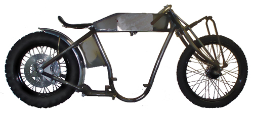
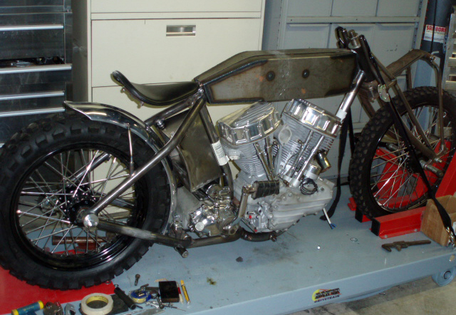
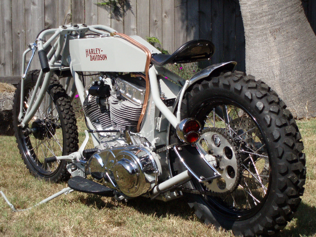
It's a terrific frame and some of the greats in our industry built U.S. Chopper Board Track Customs from Ralph of Knockout Choppers and Vicious Cycles show winner that graced the cover of American Iron recently. But there was an inherent problem with these chassis for a guy 6 foot 4. I was way too tall, but I was still intrigued.
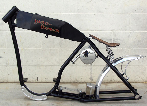


I wanted to build one of these, but in my old age status, I needed some size and forward controls. Then Rick started on his second generation model with the Paughco factory, and they called it the Factory Racer. Initially Ron built the first concept frame, this one. Rick didn't feel it fit his scrunched design criteria and asked Ron to shorten it by 6 inches and reduce the rake. Again, it put the U.S. Choppers design configuration out of my too-tall league. My project was threatened.
I spoke to Rick and told him my concerns, so he developed two frames. In fact, Rick's super-short version turned out to be way too short and he was forced to lengthen it slightly. And so this project began with all Paughco components including their highly secret manufacturing process that allows them to produce absolute classic wide and narrow tapered-leg springers. I went with the narrow job to stay in keeping with the 1915 style.
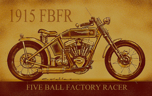
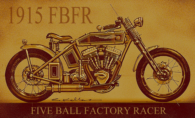
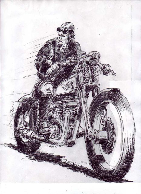
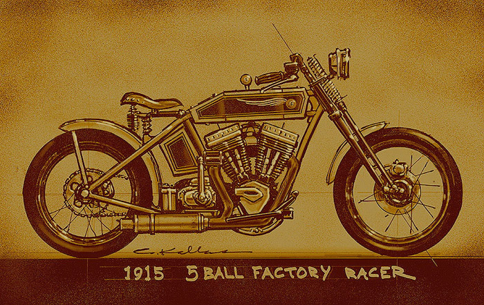
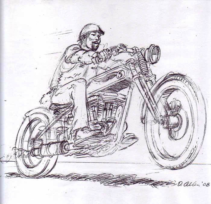
While I ordered parts I reached out to the Bikernet Official 5-Ball Racing Illustrator for an inspirational visual. I fed him information on the format and elements and he made the project come to life. I'm always inspired by each build, but for some reason the 1915 5-Ball Factory Racer held a special significance. We are planning our first Bikernet Vintage Classic Ride and gathering to Sturgis next year, and so perhaps a tradition will emerge.
Billy Lane and Chica would like to tag along when we cut a dusty trail with an assortment of vintage and replica bikes to the Badlands. We are hoping we can make our semi-central meeting place the new location of Dale Walksler's Wheels Through Time Museum in Arizona. I spoke to him this morning and he still doesn't have a desert location.
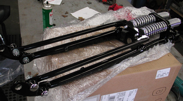
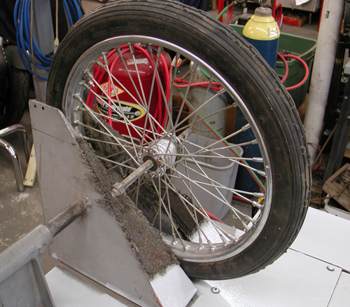
So I was pumped, and I always attempt to build the ultimate bike from a reliability and handling ease standpoint. I always have the notion that this bike will stick with me into my ripe old age; easy to work on, easy to ride, comfortable and durable. I'm not trying to build a show winner or something so exotic that it's not road worthy. I'm after the opposite. I want a bike that is tough as nails and looks that way.
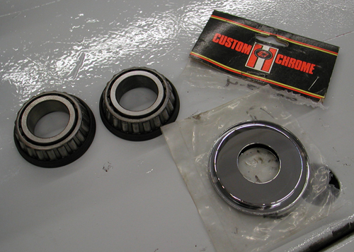
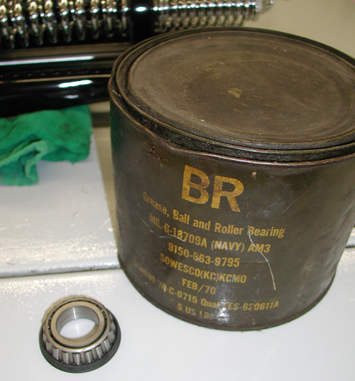
The other code I hoped to follow was one of tradition. Without getting crazy I planned to adopt as many early H-D parts as possible for a Vintage look. Paughco's catalog helped a lot with traditional '20s rectangular footboards, a vertical tool box, and flat side tanks.



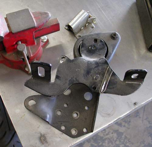
I reached out to Fred Lange for a vintage '20s sprung seat. Nash Motorcycle Company has vintage grips and DBBP in Europe makes bronze dogbone risers. Black Bike Wheels custom-builds 3.50 wide 23-inch wheels and Avon makes tires to fit.
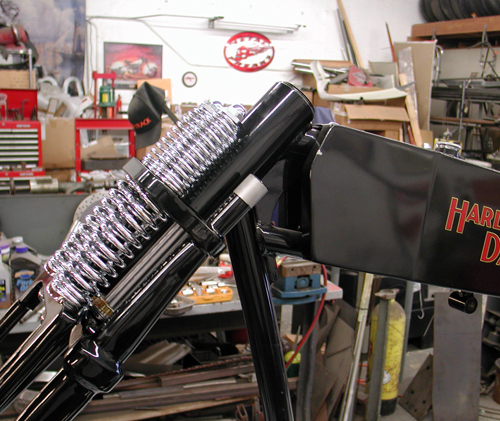
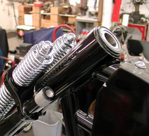
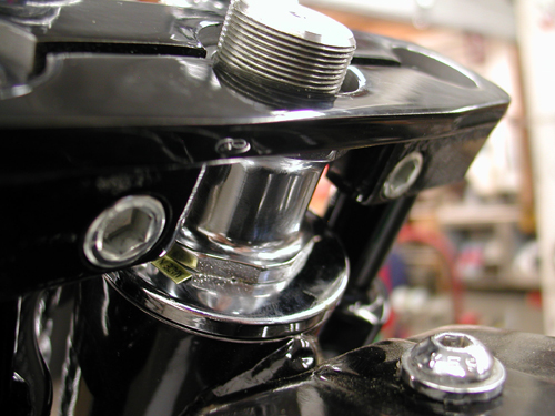
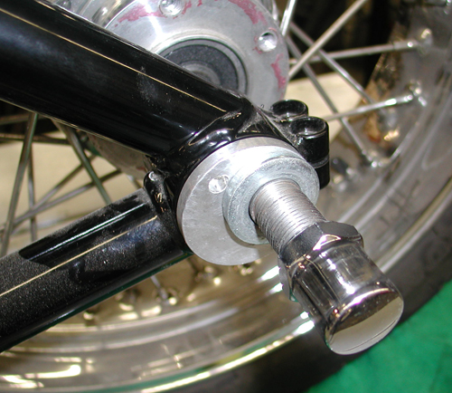
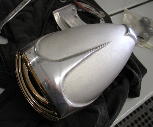
I dug through my lockers of parts for old H-D controls, kickstands and miscellaneous items from the rigid frame era and started a stack of parts. I ordered the coolest headlight, taillight, and air cleaner combination from Crime Scene Choppers, their Rapid series.
Recently, I ran across a classic shotgun-styled exhaust system with an approved Suppertrapp tuneable muffler. I was going to make my own system, but this one is killer. Part of it comes from WCC and part from Illusion Cycles.
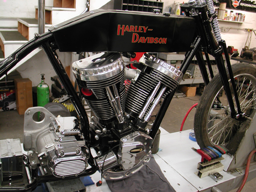



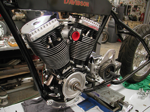
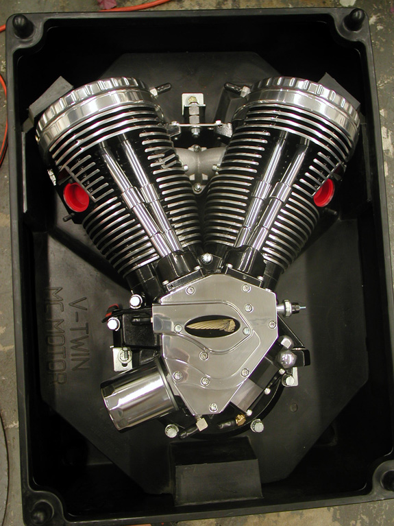
The key to the success of this project is the drive train. I sought a Crazy Horse V-Plus, 100-inch engine for several reasons. It has a classic design, renewed performance, looks and a left-side carb. I will couple it to a JIMS 5-speed transmission with a Baker kicker unit and a 5-1 shifting drum, so I can run a tank shifter and find neutral without a problem.
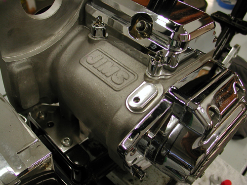
I generally run a BDL primary drive and Spyke and Compu-fire electrical components. I'm going to remount the gas tank with Bung King components and Rick Krost is building the oil bag to fit. For some strange reason I'm sick like a puppy dog today, so I'll stop here, but I will be back shortly with an update. If my head would quit throbbing I'd add some highly inspirational closing, but I'm toast. See ya next time.

1928 Shovelhead Part IX
By Robin Technologies |

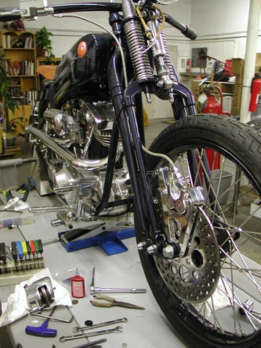
It’s time to feature the 1928Shovelhead and American Iron said theywould take it on. They’re the only bookthat accepts antique bikes. I’ve writtenabout four features for them on rare, very coolhistoric models.
No the ’28 Shovel doesn’t fallinto that catagory, but what the hell, it’sgot class. We needed to complete a couple ofdetail mods before Markus Cuff would aim alense at the blue beast. We needed matchingbrake rotors and a PM front brake system. Ipulled a front rotor from the CCI catalog andcontacted Performance Machine for theappropriate front brake caliper and springerbracket.
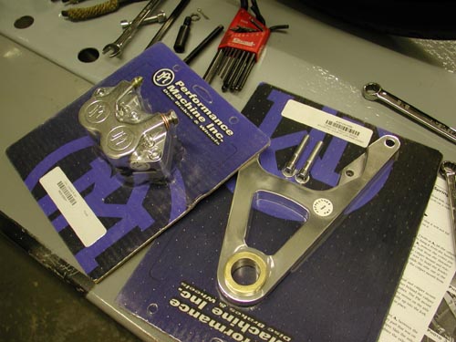
Much of the following comes directly fromthe very complete Performance Machineinstructions. They don’t mess around.There will be no doubt about the installation ofthis unit. Let’s hit it:
Before installing a caliper or rotor kit,read through these instructions completely;this will familiarize you with the way in whichthe parts fit together and the tools needed tocomplete the job.
In the course of installing these kits youwill be replacing the stock brake caliper(s)and/or rotor(s) with a high-performance brakecaliper(s) and/or rotor(s). Please pay specialattention to the section of the instructionsdealing with the centering of the caliper overthe brake rotor. Actually, I couldn’t findthis section. Generally a set of shims arepacked with calipers. Use the shims andmake sure the caliper is centered over therotor.
The brake caliper(s) used in this kit isdesigned to use DOT 5 brake fluid. Neverreuse brake fluid, don’t use brake fluidthat you are not sure is new and clean. Thisinstallation should only be attempted by amechanic with a thorough understanding ofand experience with motorcycle brakesystems.
If you plan on using the stock brakeline/hose that runs between the mastercylinder and the caliper, then you will be justswitching the line at the caliper’s banjofitting. We recommend that you do notdisconnect the line from the stock caliper untilyou have the new caliper bolted in place andare ready to bleed the brake system. This waythe brake fluid will not run completely out ofthe master cylinder before you have the newcaliper connected.
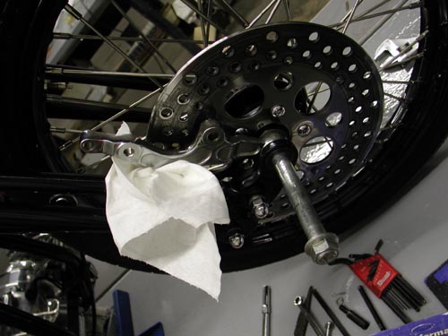
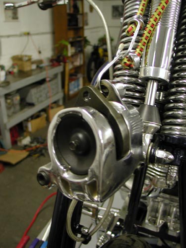
Loosen brake line and remove the twobolts, lift the caliper up off the rotor and use ashort length of wire or bungie cord to hang itfrom the handle-bars, up out of your way. Onthe 3/8‚ bolt, remove the cotter pin from therear; unscrew the lock-nut, unscrew the boltfrom the threaded bushing in the fendermount and pull it out of the caliper mount andreaction link. On ’93 and later models,use a piece of wire to hold the fender up out ofyour way. Unscrew the axle nut, slide the axleout of the fork and lower the wheel to theground. Remove the caliper mount from theaxle and the bushings and spacers. Keep thisshit around, you’re going to need it.
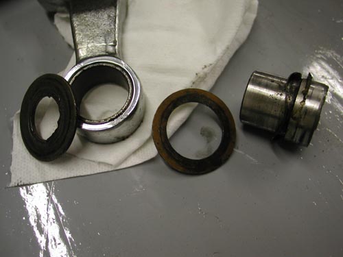
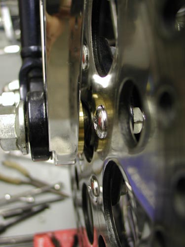
The Springer uses a combination axleseal and caliper mount bushing, with awavy-washer and bronze thrust washerbehind the caliper mount. Remove anddiscard the bronze thrust washer that goesbetween the caliper bracket and the wheel.The PM mount has this thrust washer built-in.Install the PM caliper mount on the axleseal-caliper mount bushing with the wavywasher and raise the wheel assembly up intothe fork.
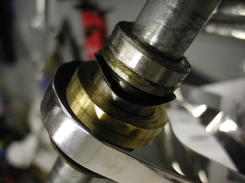
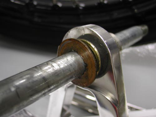
Here’s the outside brass bushing inplacebetween the rocker and the caliperbracket.
Install the stock outer caliper mount thrustwasher between the caliper mount and thelower fork rocker. This is a factory part thatwas on the fork assembly; the copper coloredside faces the caliper mount. Slide the axlethrough the fork, install the flat washer andaxle nut and tighten the axle nut to 65 ft. lbs.
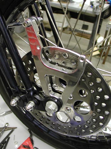
Caliper installation
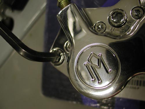
Remove the two chromed Allen end boltsfrom the Performance Machine caliper body,slip the caliper over the rotor and install the5/16 x 1 3/4-inch socket head bolts (Allens)and flat washers. Here’s where youcheck the caliper over the rotor. Step in front ofthe bike and eyeball the pads in the caliper.
Make sure the caliper is centered. Beforethe caliper is tightened down, it must becentered over the rotor; see page 3 for theproper procedure.
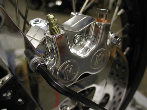
Yep, sure enough they were on pagethree. Here’s what I missed, “The centerline of the caliper is where the two caliperhalves meet. Look down from the top of thecaliper onto the rotor. If it’s offset to theoutside then you need to install mounting boltshims. Shim kit includes six shims, two each:.016, .032. .062-inch. Insert the shimsbetween the mounting boss on the bracketand the caliper body by removing themounting bolts. After the caliper is centereduse Loctite or lock washers and torque thebolts to 22 ft. lbs.”
The small print dictates that failure toproperly center calipers will impede theperformance of this fine braking equipment.They’re right. Do it right the first time.
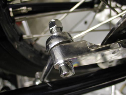
Attaching The Brake Line
First tape handle bar master lever 1/2 wayclosed. This will prevent fluid from free flowingfrom hose. Remove the end of the brake linefrom the stock caliper.Working rapidly so thatan excessive amount of brake fluid does notrun out of the end of the brake hose, attach theend of the brake line to the new PM caliperusing the PM supplied seal washers, onewasher goes on each side of the banjo fitting.
Position the banjo fitting so that the brakehose does not rub on the frontfender or other part of the motorcycle. I had toreroute my Goodridge brake line. Had to movefast.Tighten banjo bolt to 10 ft. lbs. of torque.
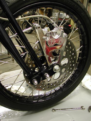
Bleeding The Brake System
You will find it is easier to bleed the brakesystem if you have a helper. First, fill themaster cylinder with DOT 5 brake fluid and putthe cover back on the master cylinder. Attach ashort length of rubber hose to the bleederscrew on the brake caliper. Put the other endof the hose into a coffee can or other suitableclean catch can.
Have your helper pull inon the front brake lever or push down on therear brake pedal five times. At the end of thefifth stroke, have your helper hold the brakelever in or pedal down.
While the helper holds the lever/pedal,open the bleeder fitting on the caliper. You willneed a 1/4 box end wrench. Air and brake fluidshould come out of the end of the hose that isconnected to the bleeder fitting.
After theair and brake fluid have stopped coming out ofthe hose, close the bleeder fitting. Your helpercan now release the brake lever/pedal. Thisaction will force the air that is trapped in thebrake system out the bleeder screw. Repeatthis procedure until the brake become firm orthere’s no air in the line.
Check thefluid level in the master cylinder after eachbleeding. Don’t let the master cylinderrun dry as this will push air back into the brakesystem which will require all-night bleeding.
Front brakes can be a bear, since airdoesn’t want to flow down the forksthrough the line and out of the caliper throughthe bleeder nipple. Some guys force fluid upthrough the bleeder nipple into the system. Ifyou want to use the above system, sometimesthe caliper needs to be raised above the barsto allow the air to flow to the bleeder nipple.
I’ve discovered that with a littlepatience, bleeding is hardly necessary. Takethe cap off the master cylinder reservior andpump the handle slightly. This allows the airbubbles to rise out of the caliper, up the lineand out the master cylinder. Tap the lines acouple of times and pump the lever slightlyuntil it’s firm. Refill the reservior whenneeded until complete, top it off and call itquits.
Leave it overnight and check it again in themorning. It may take a couple of days beforeall the bubbles are gone, but it’s abreeze.
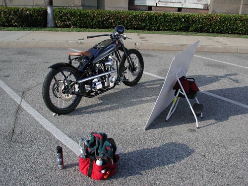
Here’s a shot of the 1928Shovelhead during the photo shoot forAmerican Iron. It looked sharp thanks to thefinal details from CCI and Performancemachine. Of course, it would be nothing but apile of parts without the talented efforts ofStrokers Dallas and painter Harold Ponteralli.Watch for the feature in American Iron, thenwe’ll post a feature on Bikernet.

Need to see the previous chapter:http://www.bikernet.com/pages/story_detail.aspx?id=9001
Witness Slips Needed Today
By Wayfarer |
|
|
Part 7 of VLXAFL5: Final Assembly Begins
By Wayfarer |
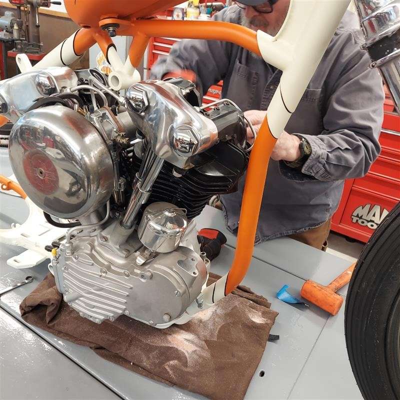
by Bandit with photos by Weed
The Paint Returned from TNT
It’s been awhile, but I haven’t dawdled. I’ve been working hard on various projects. That guy in Deadwood, who was once 45 John bought a 1960 Panhead roller/basket case and I’ve been helping with the reconstruction. I rebuilt or built and trans from a case and a sketchy box of parts. With Fab Kevin we built a front disc brake. John rebuilt the rear star hub and I helped with fitment and the rear brake.
We slid in the engine after I stumbled. I used the rear axle and a flat lift jack to jack up the bike, so I could block it, remove the jack and start to install the 5-speed trans in a 4-speed S&S case. The trans didn’t want to go so I filed and ground all the paint out of the 4-speed slots and the slot I made and welded for the 5th stud on the right. I even had to grind the rear tab on the trans case more for additional clearance.
I couldn’t run an old school 4-speed trans for a couple of reasons. It’s an alternator S&S engine and I wanted it to be electric start.
Click here for the accelerating Tech adventure with detailed photos and tips.
* * * *
Don’t stop there, we have a whole department on Motorcycle Tech since 1996. Click and build now!
https://www.bikernet.com/pages/Techs_Bike_Builds.aspx
Harley-Davidson’s 2024 Factory King of the Baggers Team
By Wayfarer |
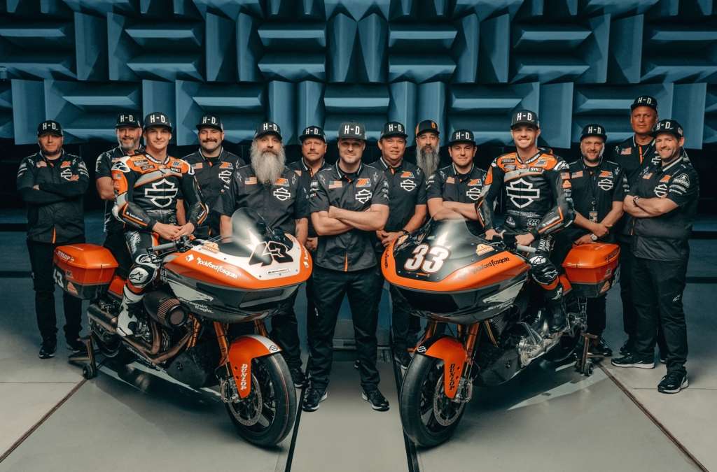
HARLEY-DAVIDSON FACTORY RACE TEAM LAUNCHES FOR 2024 MOTOAMERICA MISSON KING OF THE BAGGERS RACING SERIES
18-Race Schedule Includes Round at Red Bull Grand Prix of The Americas
MILWAUKEE (February 16, 2024) – The Harley-Davidson® Factory Race Team today launches its 2024 season with an exciting video featuring team riders Kyle Wyman and James Rispoli aboard new race-prepared 2024 Harley-Davidson® Road Glide® motorcycles based on the all-new touring platform for the MotoAmerica Mission King Of The Baggers road racing series. The video, with exclusive behind-the-scenes footage of the team, dials up the fun and irreverence of the King of the Baggers series, and will debut today on the Harley-Davidson YouTube Channel and other social channels.
An exciting special round was recently added to the 2024 Mission King Of The Baggers Championship by appearing during the third round of the FIM MotoGP World Championship at Circuit of The Americas in Austin, Texas, April 12-13. This two-race appearance during the Red Bull Grand Prix of The Americas weekend will mark the first time an international audience will see the thundering King Of The Baggers bikes in competition. In addition to the two points-paying races on Saturday, April 13, there will be a three-lap Mission Challenge on Friday afternoon with the six fastest qualifiers battling for a $5000 winner-take-all purse. This special round expands the 2024 Mission King Of The Baggers schedule to 18 total races.
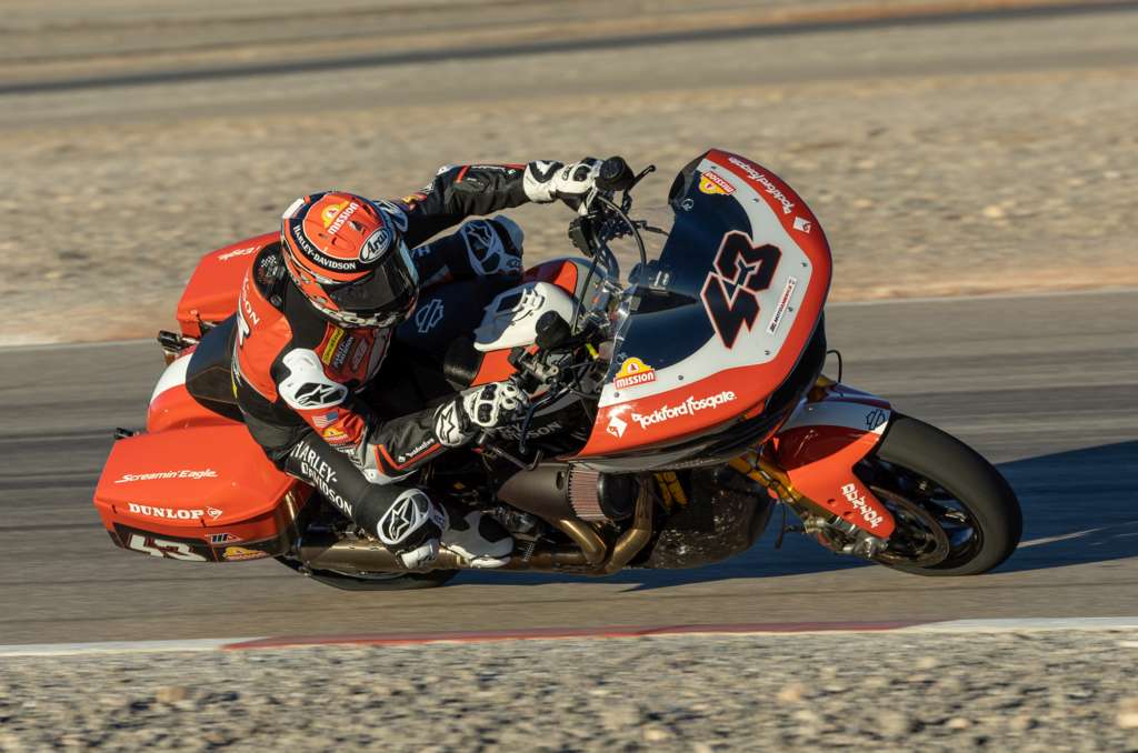
Wyman and Rispoli will compete aboard race-prepared 2024 Harley-Davidson Road Glide® motorcycles powered by modified Screamin’ Eagle® Milwaukee-Eight® 131 Performance Crate Engines. These motorcycles are based on the all-new 2024 Road Glide model, including the sleek new next-generation sharknose fairing design. Many of the race motorcycle body panels are formed with the same lightweight forged carbon fiber material featured on the 2024 CVO™ Road Glide® ST model. The team bikes also feature upgraded suspension components, including Screamin’ Eagle/Öhlins Remote Reservoir Rear Shocks, and competition Screamin’ Eagle exhaust, along with upgraded Brembo® Racing braking systems, Marchesini® wheels, and premium Harley-Davidson racing components produced by Protolabs®. The team motorcycles will appear in all-new livery featuring the classic Legendary Racing Orange color long associated with Harley-Davidson Factory Team racing bikes.
Wyman returns for a fourth season with the Harley-Davidson Factory Race Team. He won seven races during the 2023 King of the Baggers season and finished third in the season championship. Wyman is the most winning racer in MotoAmerica King of the Baggers history, with 12 total race wins in the 24 events since the start of the series in the 2021 season, plus the 2021 season championship to his credit. Wyman won the Daytona 200 in 2019.
Rispoli joins the team for the 2024 season after placing second in King of the Baggers series points in 2023 riding for the Vance & Hines Harley-Davidson team. In 2023, Rispoli won two races, and scored five second place finishes and three third place finishes. Rispoli began racing Harley-Davidson motorcycles as a teenager and earned the nickname “Hogspoli” after winning the 2020 American Flat Track Production Twins championship aboard a Latus Motors Racing Harley-Davidson XG750R. He also won back-to-back AMA Pro Racing Supersport championships in 2011-2012.
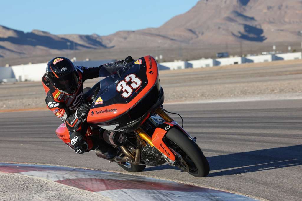
For the 2024 season, the Harley-Davidson® Factory Race Team is sponsored by Mission® Foods, Rockford Fosgate®, Brembo®, Öhlins®, Protolabs®, SYN3® lubricants, and Screamin’ Eagle® Performance Parts and Accessories.
The MotoAmerica King Of The Baggers series offers exciting competition between American V-Twin touring motorcycles prepared for competition and equipped with a fairing/windscreen and saddlebags. The 2024 series has expanded to 18 races over nine double-header weekends held in conjunction with the MotoAmerica Superbike Series. The series opens on the high banks of Daytona International Speedway in Daytona Beach, Florida, March 7-9. To experience all the King Of The Baggers action in 2024, check out the Harley-Davidson Factory Race Fan Ticket Packages.
2024 MotoAmerica Mission King Of The Baggers Season Schedule
(Two races each weekend)
March 7-9: Daytona International Raceway – Daytona Beach, Fla.
April 12-13: Circuit of The Americas – Austin, Texas (Red Bull Grand Prix of The Americas)
April 19-21: Michelin Raceway Road Atlanta – Braselton, Ga.
May 31-June 2: Road America – Elkhart Lake, Wis.
June 14-16: Brainerd International Raceway – Brainerd, Minn.
July 12-14: WeatherTech Raceway Laguna Seca – Monterey, Calif.
August 16-18: Mid-Ohio Sports Car Course – Lexington, Ohio
September 13-15: Circuit of the Americas – Austin, Texas
September 27-29: New Jersey Motorsports Park – Millville, N.J.
* * * *
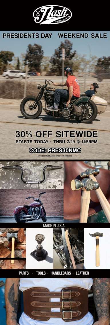
FINAL DAY 30% PRES DAY SALE – ENDS TONIGHT
By Wayfarer |
President’s Day Weekend Sale. 30% Off Sitewide.
Starts today through 19-February 12 PM
CODE: PRES30NMC
www.nashmotorcycle.com
* * * *
House Motorcycle Caucus Leadership
By Wayfarer |
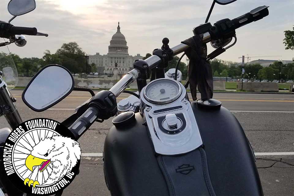
New Leadership For House Motorcycle Caucus
This week, the House Motorcycle Caucus announced changes to its leadership team. Congressman Michael Burgess of Texas, who will retire at the end of the year, has stepped down as co-chair of the caucus. Congressman Burgess helped found the caucus in 2009 and has been a tireless champion for bikers. He was the 2018 MRF Legislative Champion of the Year and we wish him well on his retirement!
The current co-chair, Congressman Tim Walberg of Michigan, revealed that Congressman Troy Balderson of Ohio and Congressman Donald Norcross of New Jersey will join him as the new co-chairs. Mr. Balderson and Mr. Norcross are longtime members of the House Motorcycle Caucus and strong supporters of biker priorities. The House Motorcycle Caucus has always been a bipartisan group, so we are pleased to see Representative Norcross, a Democrat, join two Republicans as a co-chair.
Additionally, the caucus named Freshman Congressman Derrick Van Orden of Wisconsin as vice chair. Mr. Van Orden is an avid motorcyclist who made a point to ride his motorcycle to the Capitol for his first day in office!
Thank you to all those who will lead and are members of the House Motorcycle Caucus. Remember, this organization and its sister group, the Senate Motorcycle Caucus, exist to educate, legislate and publicize the priorities of bikers on Capitol Hill.
Below is a current list of House Motorcycle Caucus members as of Thursday, February 15th, 2024.
Don Bacon (R-NE)
Troy Balderson (R-OH)
Jim Banks (R-IN)
Mike Bost (R-IL)
Angie Craig (D-MN)
Rick Crawford (R-AR)
John Curtis (R-UT)
Tom Emmer (R-MN)
Paul Gosar (R-AZ)
Glenn Grothman (R-WI)
Andy Harris (R-MD)
Dusty Johnson (R-SD)
Anne Kuster (D-NH)
Doug Lamborn (R-CO)
Tracy Mann (R-KS)
Mariannette Miller-Meeks (R-IA)
Donald Norcross (D-NJ)
Scott Perry (R-PA)
Bill Posey (R-FL)
Adam Smith (D-WA)
Pete Stauber (R-MN)
Bryan Steil (R-WI)
Chris Stewart (R-UT)
Glenn “GT” Thompson (R-PA)
Dina Titus (D-NV)
Derrick Van Orden (R-WI)
Michael Waltz (R-FL)
Joe Wilson (R-SC)
Ride With The Leaders ™ by joining the MRF at https://mrf.org/ or call (202) 546-0983
* * * *

