Hang on. This is the last of the scintillating segments on building the Sturgis Shovel before I write the treacherous saga of the ride. Somewhere we will publish a feature on the bike in a mag and on the site. Oh, there’s one other tech that will come to pass—hard line assembly. I’m waiting for a CD of images from John Gilbert of Bike Works mag.
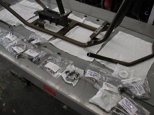
So let’s get started. I was burnin’ daylight before the Sturgis run. I saved a ton of cash going with all powder and no additional chrome or polishing. It cost me just $325 to powder all my components for lasting protection.
Throughout this article I will point out my mistakes, so you can avoid them. I did an 80 percent decent job of mocking up the bike prior to powder. That meant that 20 percent had to be dealt with after the finish was applied. Bad news. The only thing I didn’t think through or make brackets for was the ignition switch and circuit breaker brackets. That may seem minor, but wasn’t as you will discover. On the other hand it wasn’t a big deal. You be the judge. Actually, if we wired, fired and rode the bike before final teardown, it would answer all the questions. But few builders take it that far.

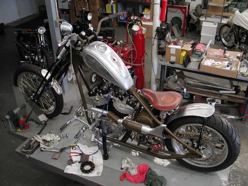
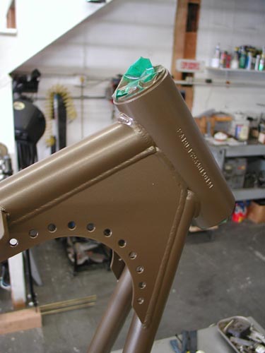
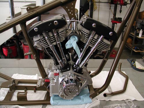
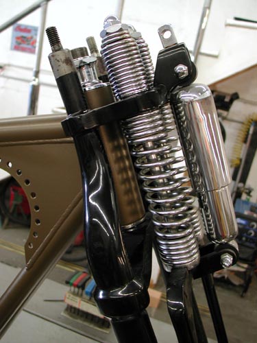
I was jazzed to toss the Paughco Frame on the lift covered with pads. Foremost Powder had plugged all the threaded holes and tapped off the neck bearing surfaces. They did a helluva job. I shaved motor and transmission mounts for a proper ground and installed the S&S modified 93-inch engine and JIMS trans. Then I could install the Paughco Springer without a balancing act.
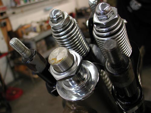
The Springer is easy to install, but takes care. I greased the bearings, slid on the dust shields and ran the whole springer through the neck. Keep in mind that installing the bearing races in the neck is not complete until the bike has been down the road. Any paint, dust or uneven race angle will mean that the bearings will seat further once on the road. Ride it for a week then lift the front end off the ground and jiggle the wheel by the axle. If there’s any movement or dangerous slop, take the bars and top tree off once more and tighten the stem nut until there’s just a hair of drag. Long front ends are more critical because of the leverage against the neck.
I didn’t bolt down the engine and trans hard, just the tranny plate which ultimately I had to loosen. The engine needs to be completely at ease for the BDL belt alignment so I just spun some stainless bolts into place. Then I installed the front wheel with Doherty spacers, the Brembo brake caliber and centered the wheel. Keep in mind that Brembo supplied the bracket, which is designed to replace a stock, late-model Harley springer brake system. I didn’t have the proper spacer, but a Harley shop had one and I was good to go.
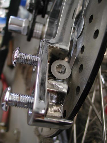
Then I installed the Brembo Caliper. They supplied me with a series of shims. I used feeler gauges to determine centering the caliper over the rotor and stacked the shims until it was set. This is an interesting bumbling, experienced manner for writing articles. I have the insight of riding experience behind images of the bike yet complete. Ultimately we removed the front fender.
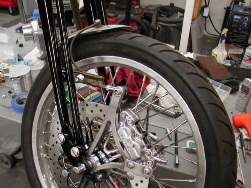
I build the front fender, single sided bracket after Kent’s, from Lucky Devils Metal Works in Houston, caliper mounted fender mounts, which work perfectly. My problem was the initial position of the caliper, too far forward. So I mounted it on the heim joint rod which didn’t work. When the bike went over a bump the front lip of the fender rode up with the caliper and the rear lip rode down with the springer touching the tire. It had to go. So I rode to Sturgis without a front fender ducking rainstorms all the way.
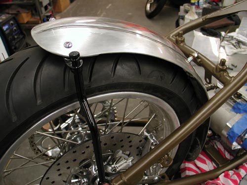
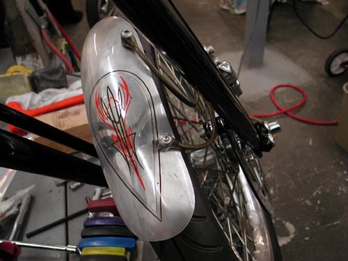
Next I installed the rear fender. Keep in mind that the rear fender, the oil tank and the rear wheel fight for the same spaces. They almost need to go together simultaneously, especially the oil bag and rear fender. Everything slipped into place with nyloc nuts, stainless Allens and red Loctite.
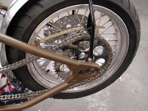
At the time I ran stock gearing with the JIMS 6-speed, until I discovered that I was faced with running a kicker. I didn’t change the rear wheel gearing from the 51-tooth, but I should have. This evening I’ll install a Custom Chrome flat (Sportster styled) 48-tooth sprocket and hope to knock the revs down seriously.

I also mounted the rear Brembo brakes and centered the caliper over the Brembo rotor. No problem. Even my Softail styled anchor bracket worked perfectly welded to the frame and tucked the caliper between the frame rails.
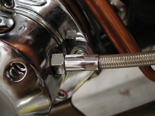
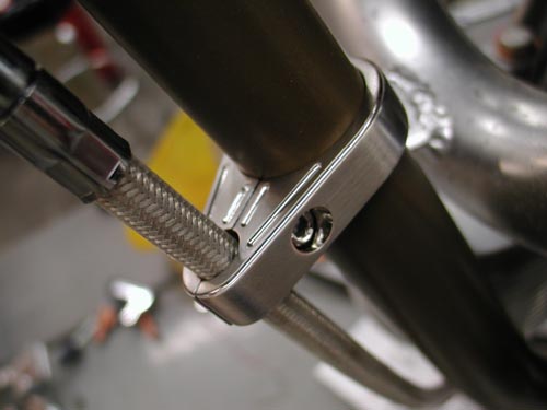
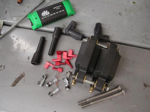
While I’m messing with brakes I’ll cover brake and clutch lines and cables. Instead of making up lines I ordered RevTech pre-assembled lines from Custom Chrome plus all the fittings washers and fasteners. Keep in mind that the front brake master cylinder uses larger master cylinder banjo bolts. They come in 10mm and 12mm. Watch out, and don’t hesitate to order a couple of extra bangos bent at different angles to make sure you’ll have what you need.

I measured my lines and clutch cable lengths a number of times then added an inch for safety. That’s where making your own lines can be helpful. Keep in mind that the front end will turn (clutch cable) and depress (front brake). You’ll need some slack. Plus you might change the angle of your handlebar levers, which will impact the position of the cables and lines. I used Tephlon tape on most fittings although some builders don’t recommend it. Since most of this stuff is chromed, I like the extra sealant.
I use only DOT 5 brake fluid in my bikes, ‘cause I can splash the shit all over the place without concern for paint damage. In many instances you can fill the master cylinder and rock, just by waiting for the bubbles to rise. Another key is to find the right pump can and fill the lines, caliper and master cylinder from the bottom up. Use a new pumper or a pump that’s dedicated to brake fluid only and attach it to your brake bleeder on the front wheel. Most of the time that works like a charm.
I’ve found that most front brakes will basically bleed themselves. Fill the master cylinder on the bars and pump it slowly allowing the bubbles to rise. Let it set overnight and most of the bubbles will rise just by pumping it with short strokes at the lever and watching the bubbles jump to the surface.
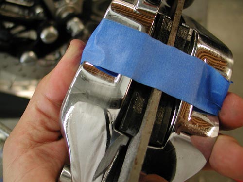
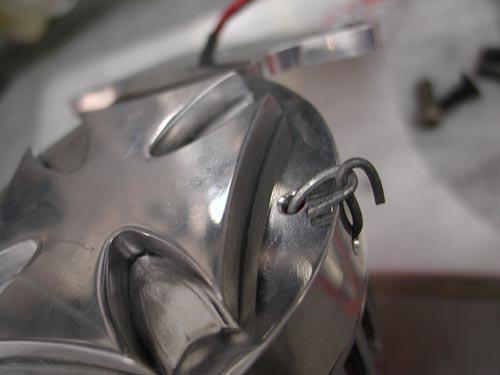
In this case I discovered that some air was trapped in the caliper, so I pulled it off the bike, taped a file (the same width of the Brembo rotor) and turned the caliper so the air could escape through the bleeder nipple. I bleed it a couple of times then returned the caliper to its rightful position. She was good to go.
The rear brake wasn’t so easy because the air couldn’t rise to the master cylinder. I bleed it from the front and the rear, and I think it still has air in the lines although the Brembo brakes worked fine. I received a lot of compliments and comments on the brakes, which I found strange. Brembo has a terrific reputation, but not on Harleys. Riders were surprised to find Brembos on a Chopper.
Now for the clutch cable. First I was confused about which cable style to order. I hope to put together an article on it in the near future. I picked the most common late model Evo cable and measured the length several times. Here’s the key. If you’re not replacing a stock cable you have no notion of the length. I pulled a stock cable and measured it, but I didn’t know what model it came from. I went by the length of my stock cable and found the 1990-1999 Fatboy cable length. Then I measured the extension due to the Paughco Frame, CCE risers and CCI bars. Much guess work. If I had all the bucks in the world I would have bought three cables lengths.
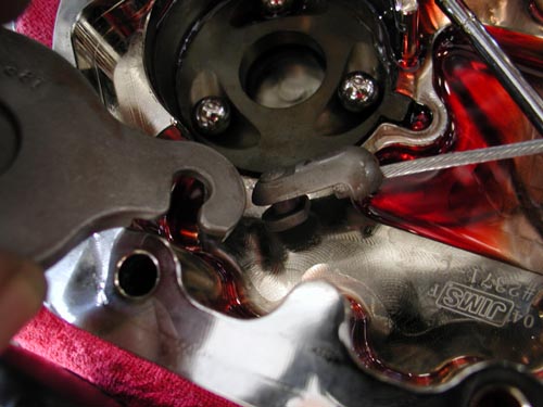
The end cap cable is the reason Baker, JIMS and RevTech transmissions come with a fresh gasket and a quart of transmission oil. They know that you’ll be forced to pull the end cap to install the cable in the ball driven throw-out bearing mechanism. It’s simple but cumbersome. Don’t loose the balls. You’ll need a massive C-clamp removal tool to pop that sucker free. Carefully lift the inner ramp and remove the cable coupling, attach the cable, which you have already screwed into the trans face cover. Return the coupling to the inner ramp by watching the puzzle face. Then put the ramp back in place and the retaining ring and bolt the face cover back into place. Don’t forget to add at least 20 ounces of Trans fluid. It will hold 24 ounces dry.
I learned something on this trip. If water gets in the trans it will act up, shift strangely. Drain the fluid and change it. Check your vent.
I ran the cable several ways to find the path that fit best, didn’t rub the frame or catch on anything. I used one Arlen Ness cable clamp to secure it and hooked the cable into the greased tephlon bushing in the Joker Machine handlebar control, then replaced the small C-clamp and I was ready for final clutch cable adjustment after the BDL primer was installed.

I’m going to cover the 300 BDL installation here and try to explain my shift. My plan was to run the Compu-Fire engine based electric starter system designed by Giggie before he left and took a job at Rivera. Rivera is making inner primary plates for this new system, but when I contacted them Ben Kudon’s response was hesitant. They weren’t ready. Of course I contacted our long-time sponsor BDL and initially they weren’t scheduled to make units, then I was pleased to find out they were, so I ordered one. But Sturgis crept into the picture, and suddenly I was without a starting system and coils hanging under the oil bag interfering with any new starter install.
I had a 300 BDL belt system and a starter but no place to put it. Kent from Lucky Devil shrugged his shoulders and said, “Why don’t you run a kicker?”
Sinwu ripped off her top, jiggled her tits and said, “You have one from Muller in Germany.
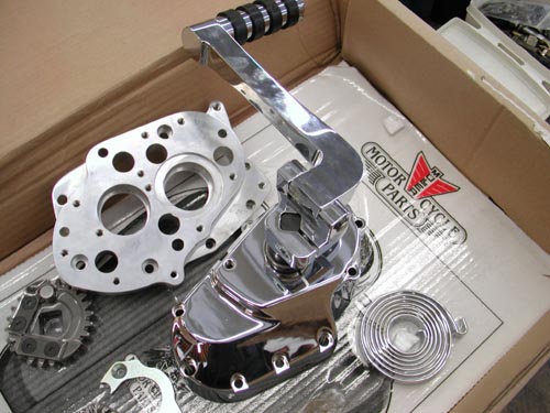
I jammed down the headquarter stairs to the shop and tore open the box. I was jazzed. This is one of the coolest kicker systems to come along. It cleared the rear exhaust pipe and the kicker arm was stylish, unique and strong. I couldn’t believe my luck.
The JIMS 6-speed lined up with the BDL inner primary like a dream. All I needed was to pull the tranny face and press off the trap door, then replace the trap door and tranny cover with the Muller system. Muller even shipped a clutch ramp system that afforded smoother clutch action.
Hell, I’d even build a cool brass plug to cover the speedo-cable hole in the side of the JIMS trap door.
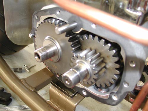
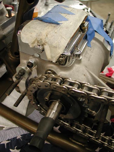
All went well until I removed the JIMS trap door to discover the 6-speed protruding gears. The door was machined to accept the gears and the 5-speed door was not. I was stuck. I contacted Muller in Germany for a 6-speed replacement door. No answer. I called JIMS and ordered the kicker they distribute for the 6-speed. It never arrived, so I called Custom Chrome. If I could order a 5-speed quick, I could use the Muller system. They responded and in three days I had a Rev Tech Replacement complete with kicker and 23-tooth chain sprocket. I yanked the 6-speed and began to install the Rev Tech 5-speed in 4-speed case with a five-year or 50,000 mile warranty.
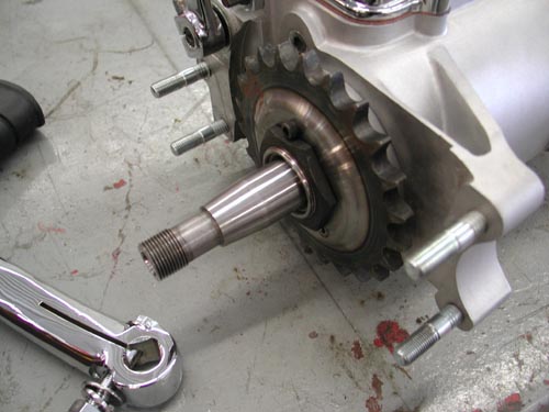
At this point I should have replaced the rear 51-tooth sprocket with a 48 or perhaps a 46, but we’ll see. I removed the kicker cover and installed the clutch cable once more, sealed the tranny and filled it with 24 ounces of fluid.
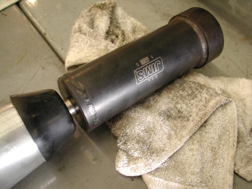
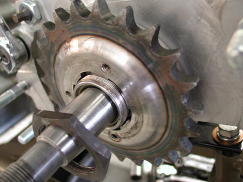
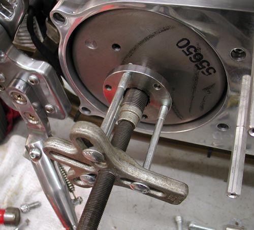
I pulled the massive, left-handed, mainshaft sprocket nut with a JIMS special tool and flopped it around backwards to afford me the clearance I needed for the RevTech chain to pass the 180 Avon tire. I locked it down with the JIMS tool and an Allen setscrew and red Loctite. She was good to go.

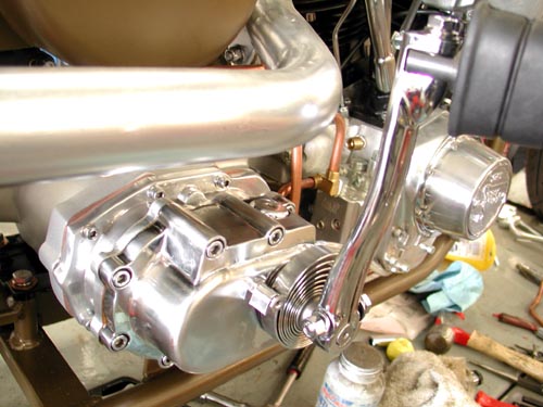
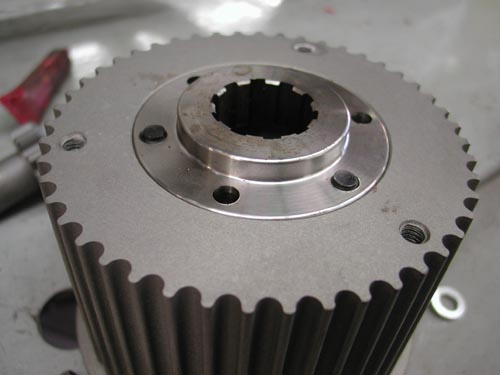
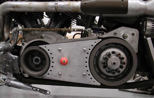
Next, I needed to set up the BDL 300 belt drive system and the Compu-Fire Charging system. I slipped in the Stator, then the small tapered washer, followed by the Compu-Fire Rotor. It’s pasted right on the rotor not to smack it with any hammers. You might knock one of the magnets loose.

According to the rules sometimes the offset pulley mount doesn’t need the massive flat washer/spacer for proper alignment. But the first move includes installing the inner primary with the engine and tranny loose. I used never-cease on the threads of the transmission and tranny Allens to prevent damage to the threads. Take it back—first I had to remove the inner primary studs from the transmission. They were tight as hell and I used Yield and heat to set them free. Then I positioned the engine and the Trans with the primary.
I ran into problems. Nothing wanted to line up. I called a couple of buddies for guidance. I held the engine where it was with a shim under the front motor mount. Then I bolted the primary to the engine and trans. The front of the tranny raised almost .100. I started looking for shims. Bob from BDL told me the code was to shim the tranny plate and not the tranny, so I went to work. It wasn’t a problem to scour around for the right thickness washers. Soon the transmission was aligned, the primary fit easily and there was no drag on the transmission mainshaft.
Next, I needed to check the pulley alignment. I installed the pulley using the insert then the pulley and Allens. Since I would be removing and replacing the parts, I didn’t drive the alignment pins into the insert from the rear just yet. I discovered another glitch. I needed some washers or shims behind the engine pulley for alignment. I also discovered that the mainshaft nut wasn’t bottoming out, so the rotor flopped around. That wasn’t right.

I’ve installed a dozen BDL systems without major alignment problems. It takes patience, but once it’s correct, she will last and last. This is a tapered shaft transmission and once it’s installed it doesn’t slip off without a JIMS transmission hub puller tool.
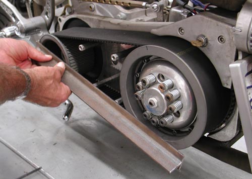
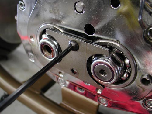
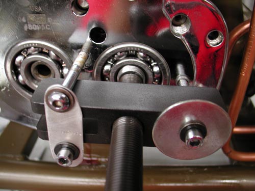
With the pulley and the clutch in place you can test alignment a couple of ways. I used a cast T-Bar across the faces of the pulleys. They need to be exact, which means shims behind the engine pulley.

I made a mad dash to Walkers Machine and bought all the goddamn shims he had. The massive washer that comes with the rotor was only .035 too large. The next item was the inset in the engine shaft nut. I had to machine it to slip over the protruding shaft. This is also an area that takes some running and retesting to make sure it doesn’t seat and settle in, out of alignment. It’s easy to spot a problem. You’ll notice rubber dust around the pulley where it’s riding against the lip.
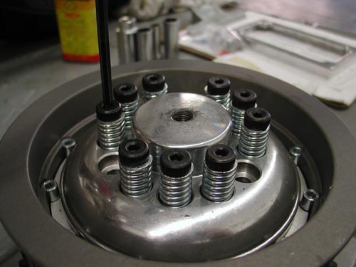
Remember that the clutch nut is also left-handed. Then the clutch slips into place and with some tugs and working the belt gently, it goes on. If not use two chunks of wood a large bolt and a socket to gently push the pulleys apart. Once it’s run for a while it will be much easier to remove and replace.
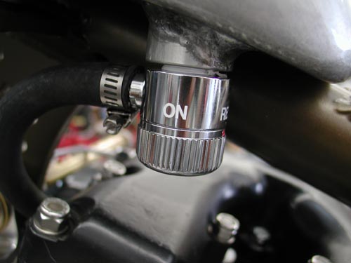
Okay, so I installed the tank, with the Spyke petcock and stripped the spigot threads. It hung for most of the ride. We’ll cover the tank more in the ride saga, so hold on. The seat was also a challenge. I slipped off, so I changed the seat, to one with a lip, then changed it back an added taller springs. That worked.
With the primary aligned I still used never-cease on the primary threads because I knew that I would remove the inner primary once more.
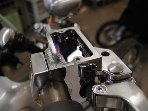
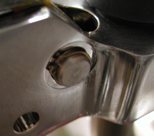
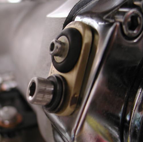
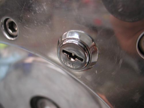
Hang on for this one. I needed to find a place for a toggle switch/ignition switch. I also had this massive aluminum starter motor boss on the inner primary that was going to waste. So I drilled out the starter shaft and installed a marine ignition switch. I glued it in place with a two stage epoxy then drowned it with liquid electrical tape, two coats. It seemed perfect except that the key sang in the wind only 1 inch above the peeling primary belt. No key rings or dice.
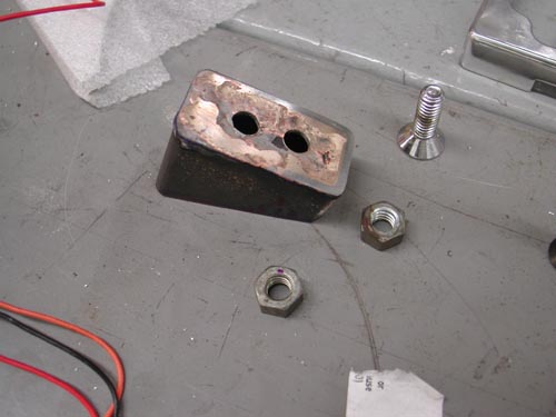
On the inside of the primary I made a brass strap that ran from one starter mounting hole to the other, holding two circuit breakers. One was a 15 amp for the lights and a 30 amp for the ignition. This became a very tight electrical area, dangerously close to the whirling CCI O-ring chain. As it turned out the circuit breakers were a hair or two from the coils. Cozy. I made a couple of wires long enough so that I could remove the primary and set it next to the bike to work on wiring issues.

The next thing I knew, under initial testing, the whipping chain chipped at the aluminum, dangerously close to the electrical. Larry Settle, of Settle MC Works loaned me a chunk of tephlon, which I carved and made a buffer, which worked perfectly to protect the chain from nearing hot wires.
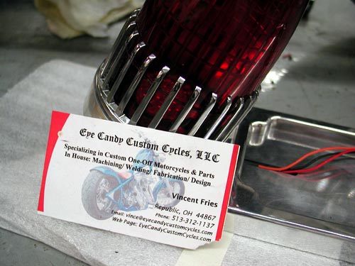
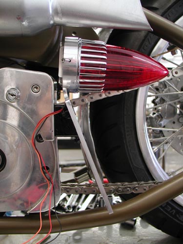
Then came the Eye Candy Custom Cycles ’59 Cadillac taillight. They also make an old Ford style light, which I prefer, but I felt the need for side visibility, especially on the right. The mounting called for the primary once more to hold the taillight/brake light. Finding the proper location was a chore. It either rode too close to the chain or the mounting called for screws through the frame or into the wiring loom. I monkeyed with it for hours and finally designed a tough mounting system that might survive. All went well, but the frame rail still blocks the light and I might move it outbound.
I ran the thin sparkplug wires through the frame in shrink tubing, wired the coil and the Joker machine brake switch and headlight through the hole in the frame too close to the fork stop. Even on a simple chopper an idiot can find his way into trouble.
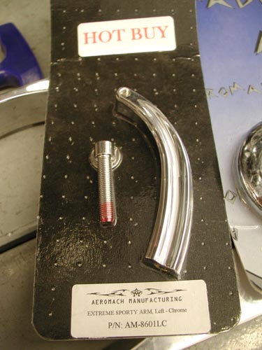
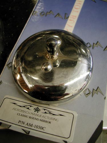
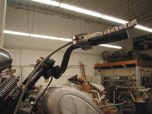
Finally I mounted the stylish Aeromach mirror on the left bar only. It came with all the hardware needed and never gave me a problem. I know I’m missing a link or two, maybe a necessary credit. Don’t hesitate to drop me a line if you need a question answered. You can reach me daily at Your Shots or drop a line to Bandit@Bikernet.com.
Over the next couple of days I will attempt to complete the first saga of the ride to Sturgis. I hope to launch it on Friday. In it I will dig into the problems I encountered, mistakes I made and how I fixed them. Hang On. But beyond the glitches, actually the wiring worked out fine, but I should wire in a kill switch. The bike rode well, comfortable for a rigid, started without major hassle and ran all the way to Deadwood. I can’t complain.