Doug Coffey’s RetroMod Panhead Part 4
By Robin Technologies |

Bikernet Project: Charity Bike, Widowmaker Style
By Robin Technologies |
“A man’s got to know his limitations”-Dirty Harry
The Widowmaker crew is ready to do everything from rebuilding the top end of your old Sportster, fabricating a set of head turning handlebars, or adding class to your fresh-off- the-showroom floor Milwaukee Iron, by installing Hank’s custom two-into-one pipes. Then giving her the iconic Widowmaker designed and fabricated intake so she can breathe 15 horses faster. Your ride isn’t made-in-the-USA? No worry, Hank has a solid record of having a complete disregard for the national origin of any type of stray bike landing on his doorstep. He’ll take it and improve on your ideas, or, like he did two years ago, just take a crotch rocket, chop it up, lay his magic welding rod upon it and get top prize at the Ray Price Capital City Bike Fest in Raleigh, NC.
Each year for the past eight years, the Widowmaker family had been organizing a very successful ride raising money to help families deal with their child’s medical expenses. This year is different; Hank is fabricating a custom motorcycle which will feature his signature hand made parts recognizable throughout North Carolina as the Widowmaker brand. The plan this year is to sell raffle tickets and raise $25,000 and give five local families in need, $5,000 each, to help with the medical care of their child. We caught Hank early in the planning stages and wanted to share his progress of this project to the announcement of the winner on September 26th at Ray Price Harley Davidson’s Capital City Bike Fest in Raleigh, North Carolina.
Bikernet is going to follow Hank through the process of building a custom chopper and staying within the basic interactions between: cost, skill level and availability of tools. This is the first in a series of five articles in which we will be going over some issues that need to be addressed prior to putting fire to metal or pen to paper.
Here’s Hank layin’ it out straight for you in his words: Set the goal and make a plan…then be flexible while you work towards that goal. Reaching that goal is the successful art of harmonizing your choices with your plans within the parameters set by your skills, or as Dirty Harry would say, “A man’s got to know his limitations.”
Be honest in evaluating your skill level; choose a bike that works within your ability and the tools you’ve got in the shop. For example, I would not recommend a 2005 fuel injected V-twin to anybody but an advanced builder. If your strong suit is not electrical, stay away from electronic bikes. Stick with the basic skills for a basic drive train and fuel delivery. Use the theory of K.I.S.S.- Keep It Simple Stupid. A carbed Sportster has been a simple and proven canvas for decades of custom builders of all skill levels. Carbed metric bikes are getting more attention partly due to popular magazines such as The Horse-Backstreet Choppers and Cycle Source. The metrics tend to lose their value quicker yet remain reliable, but the metrics need a more fluent skill set. Sportster tooling is basic, aftermarket parts are readily available.
Choosing a bike. Choosing your donor can be difficult. However, surfing the internet somewhat simplifies this option. Knowledge is power, knowing people helps. Know your surroundings and what you are willing to do to get what you want. What are you limitations? If you find a great deal on a bike but its 1,000 miles away, is it worth the drive? Consider any time, effort and expense in acquiring the donor bike or parts for your project. Speedy decision making is the key to sealing any internet deal. If you find a good deal, jump on it. There are plenty of up and coming backyard builders, and many are out there in the fast lane. This is where your skillset, tooling, and above all- your planning comes into play. Choosing a bike that best fits your ability is better than choosing a bike that better fits your wallet. Knowing your limitations will save aggravation and keep you from wasting time and money. Decide if you want a running bike or not. Running bikes are easier to start with. You’re trying to re-engineer the bike completely. If you decide an engine rebuild fits your plans, your market for a donor bike expands considerably.
Choosing a wrecked bike. First question, does it run? Look at causes of failure. How bad of a hit did the bike take and where? What are you changing about the bike and how does this affect what your plans are? Is the front end in the frame? Are you replacing the frame? Looks can be deceiving. Frame can be bent. Always check. Where was the impact? What deemed it totaled? What condition is the engine? Compression Test? A compression test tool can be easily found at your local auto parts store. Review the specific bikes requirements before performing the test. Basic actions, remove spark plug, disconnect ignition coil, install tester. Spin engine over with throttle open. Evaluate readings. Every engine has different specs. Know your specs. You should not have a difference of more than 10% from one cylinder to the other. This will give you an idea of overall internal condition. An easy way to decide if you have leaking rings or valves is to squirt some oil into the cylinder. Retest them if you have a poor reading. If your value goes up, the rings are bad and the valves may be ok. How long has it been sitting? Perform a Cylinder Leak Down Test using another tool easily found. This can be confusing to understand. You will have 2 gauges. One showing the air coming into the cylinder, the other showing a percentage of air lost. The more air lost, the worse the condition of the internals of the engine, i.e. valves, rings, etc. Make sure the valves are closed and engine is on Top Dead Center (TDC) for that cylinder. Does it run? Get a grasp on the variables of how long it has sat, what is the overall shape of bike? How many miles? Is the speedo stuck on a certain speed? This is a good indication of speed of impact. Is it water cooled? How will this affect your ability? Can you rework the design of the cooling system? Have a game plan for the bike. What parts will you have to fabricate to use in your build? Again, what is your skill set and tooling for the bike? Plan ahead. How far can your abilities carry you and what do you have to buy or source. Make sure your plans also consider the laws of you state for signals, light sizes, handle bar heights, fork lengths? Look at the overall of the bike. What is damaged, where, why, how come?
In this build, we are using a wrecked ’99 Yamaha Road Star 1600. The insurance company determined the bike was “totaled” based on overall damage vs. cost of repair and value of a repaired bike. The bike was running good and in good riding order. The majority of damage was isolated to the front and right side of bike. Fender, exhaust, tire, turn signal bar, etc. (insert pix here). (talking about points of impact, overall condition and damage). But the overall running works of the bike were intact and in good running order.
Having a plan. For this project, we chose this bike specifically based on availability and cost. Knowing our skill set on the front end, we knew this bike would be a challenge, but be a great build. We already planned ahead. We had a Crafttech frame with a 240 back tire that needed a large displacement motor. The 1600 cc Road Star engine fit the bill. Now this comes into tooling. Keep posted to see how the overall pieces are made to fit. See you next month.
SPONSORS
Triangle Cycles
Grip Ace
Chop Rods
Fastnel of Roxboro, NC
Amzoil
Ah-maiz-in Paint and Finish
Carolona Custom Powder Coating
Turner Asphalt of Raleigh, NC
Camp Bow Wow
Chandler’s Towing
Peak City Trucking
Carolina Ceramic Coating
Brandon’s Harwood Floor and More
Bennett’s Performance Dyna Build, Part Two
By Robin Technologies |

Sorta the same equation in reverse fits Bennett’s. They are located on an alley, but it’s about as clean and wide as a comfortable two-lanner, and the buildings are pristine and orderly. Hell, there’s even some landscaping bordering the buildings. Eric and his dad keep the shop tidy and it’s open and painted white on the interior and the exterior. Makes it easy to take tech shots.

So we got to work. Eric hadn’t ridden his own motorcycle in six months, broke up with his girlfriend three times, and needed his two-wheeled Valium. Working with D&D, they altered a stock D&D system to fit ’91 to ’13 Dynas. The heat shield was modified and the system was ceramic-coated for a long-lasting satin black. He also had to modify the mounting bracket for the performance pipe system. Eric is going to share his mods with the D&D gang so they can make adjustments to their manufacturing process for these model years.


Eric’s first move was to avoid a potential problem with the 5-speed tranny main shaft inner primary race. They occasionally drift inwards from the inner primary toward the tranny main shaft seal and damage the threads. A malady solution included installing a JIMS inner primary bearing upgrade Kit.


Here’s what the JIMS team has to say about it: Thinking of running an open primary system, or looking for added durability in your high output engine? JIMS now has a double-row ball-bearing with seal and retaining ring kit.
For use on 1990 to 2006 FLH and FXST, and on 1990 to 2005 Dyna models or any 5 or 6-speeds using H-D bearing No. 9135.
Note: Not compatible with Bandit clutch kits.

Eric used his Custom Cycle Engineering swing arm punch to remove the stock bearing. Then he used JIMS tools, including the race puller No. 34902-84 and the seal installer No. 967, to press in the bearing to the perfect depth. The JIMS kit removes the main-shaft bearing race.


With the bearing pressed in perfectly, Eric installed the snap ring with the flat side toward the transmission, then the JIMS seal. It was time to install the inner primary using 22 foot-pounds of torque on the 5/16 bolts with a dab of blue Loctite.


He was ready to install the new Rivera Pro Cutch, but first he had to press out the stock clutch hub. The performance differences in the clutches were obvious. The difference in the fiber surface areas was substantial. For big-inch motorcycles, the more surface contact area, the better.


Per the Rivera/Primo instructions, we needed to soak the Rivera clutch plates in ATF transmission fluid before assembly. “If we don’t, Ben Kudon, from Rivera will bust my balls,” Eric said trembling. Per the instructions, we soaked them for 10-15 minutes.


While waiting, we installed the stock compensating sprocket using a 2.5-inch socket and Loctite, and the primary chain adjuster. Eric installed the clutch hub with a 1 3/16 socket, being careful to handle the left-handed threads. Then he installed the first thick steel plate into the hub, followed by a fiber, then steel, and then another fiber plate.

Eric runs ATF fluid in his primary. With the pressure plate in place, the diaphragm and the retainer, the clutch was a done deal. “Don’t over-tighten the fasteners against the locking ears,” Eric pointed out.

Eric uses JIMS guide pins to hold gaskets in place, so the primary could be slid into place without fighting the gasket. They are easy to make, or just buy a set the perfect length from JIMS. He tightened the stock primary to 120-inch-pounds of torque.


Between the last time I darkened the Bennett’s Performance door and this point, Eric and John O’Keefe from Bennett’s Performance had a brain fart to machine only Twin Cam cylinders to give them a drag bike appearance. Eric volunteered to be first and tore his engine apart again.
[page break]


John O’Keefe has given this signature look a new name: Branch Race Cut Cylinders. Eric chose to be the trial run and they cause a stir around the shop. Currently, the Branch team doesn’t have enough cylinders to offer an exchange service, but you can send your cylinders out, and depending on the shipping service you select, get them back within a week.


He installed the carb with the isolator block and new S&S O-rings dry. “If the surfaces are in good shape,” Eric said, “you don’t need grease or sealants. They just cause problems for the next mechanic.”
We took a break, since Eric was working with a Speed Merchant and Alloy Art on a couple of custom products, plus a couple of items needed powder-coating. Eric was anxious for final assembly and to fire the monster for the first time and go for a ride.

When I returned, Eric was installing a new H-D floating rotor on the rear wheel of his bike. “You can’t install the rear wheel until you pull the wiring into place.” Eric pointed out the wiring pocket in front of the rear wheel cavity, which is very tough to reach with the rear wheel in place. “Only ’05 and earlier Dynas were set up this way. It’s a pain in the ass.”


Okay, this may get a tad confusing, but I’ll do my best. Alloy Art is a machine shop and they build parts for companies like Speed Merchant and Harley-Davidson. They machined these Speed Merchant triple trees for Dynas, in keeping with Buell configuration and agile handling. You can see the difference.


He greased the neck bearing and the Timken, and began to slip the fully adjustable stock forks into place. With the dust shield in place, the top triple tree was added.


Eric chose to run Alloy Art super clean rear turn signals, no fronts, and an Alloy Art tight billet headlight and grips. He also installed good and tight Alloy Art urethane riser bushings. Next came his own headlight mount bracket and the Alloy Art billet headlight, plus his handlebars and controls, and the Dakota Digital dash, speedo, tach, and data acquisition system. Then he pulled the stock wiring harness runs into place under the rear fender and installed the stock wiring plugs.


The Alloy Art rear turn signals required drilling one hole for a signal wire. Then it was a matter of installing his pre-ordered Goodrich front and rear brake lines. He installed and adjusted the pull throttle cable first, then the push. He slipped chunks of ½ inch black shrink tubing over the dual throttle cables and used them as guides. Once the cables were run and comfortable, he used a heat gun to tighten the shrink-wrap.




Sources:
Bennett’s Performance
Rivera Primo
S&S
Branch O’Keefe
Alloy Art
TEL: 626 963 5021
FAX: 626 335 3685
CONTACT@ALLOYART.COM
154 S. VALENCIA ST.
GLENDORA, CA 91741
Speed Merchant
www.thespeedmerchant.com
info@tsmracing.net

How to replace grips on a Harley-Davidson by J&P Cycles
By Robin Technologies |
Today, J&P Cycles shows you how to replace grips on a Harley Davidson motorcycle. From removing your old grips and adding new grips watch the entire process take place.In this video they use a 2013 Harley Davidson Softail Slim for demonstration but the process will be very similar for all motorcycles that utilize dual throttle cables.
Doug Coffey’s RetroMod Panhead Part 3
By Robin Technologies |

Rebirth of an American Classic: Transmission Rebuild
By Robin Technologies |
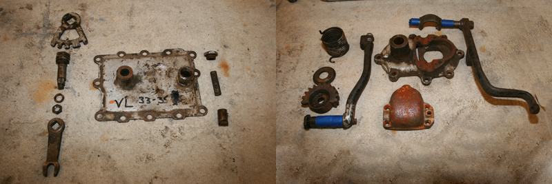
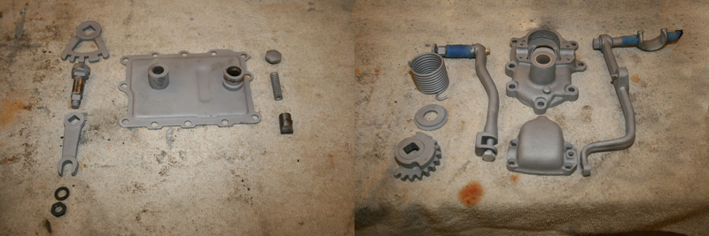
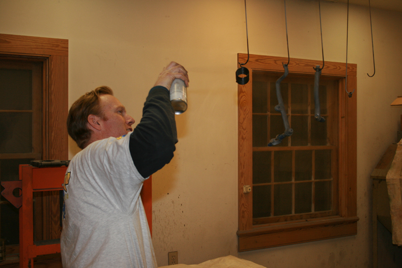
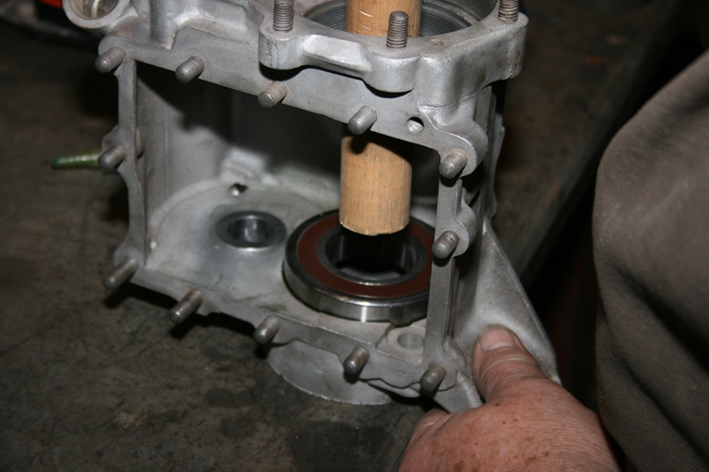
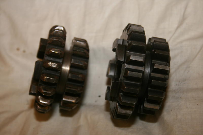
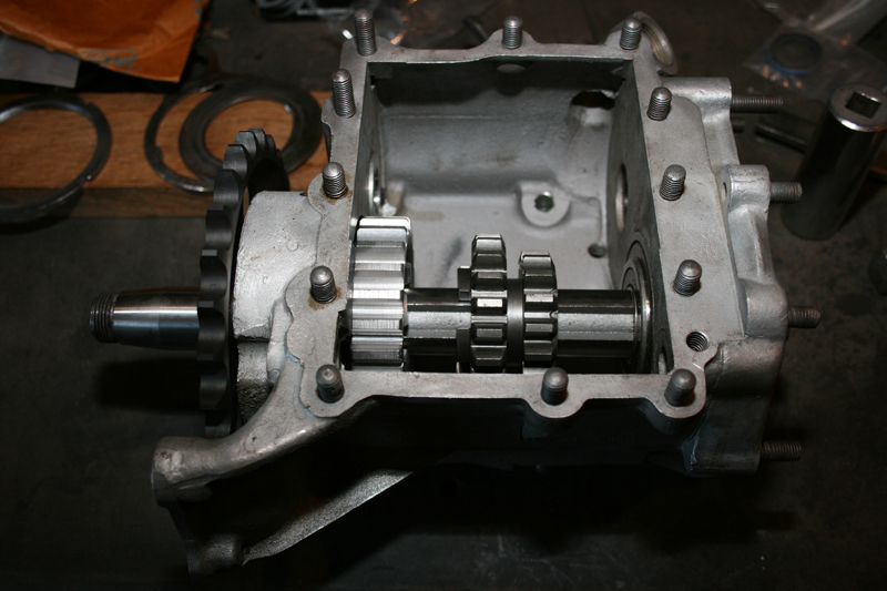
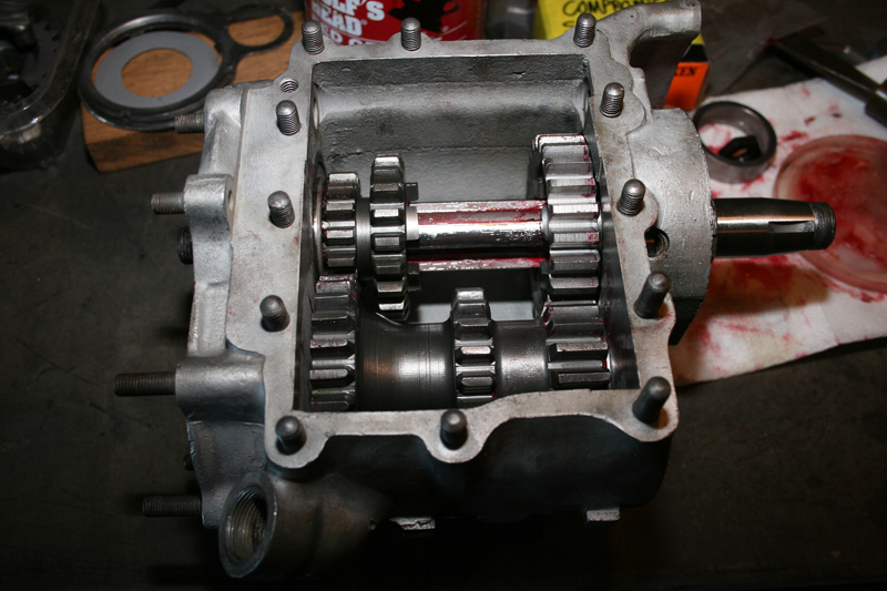
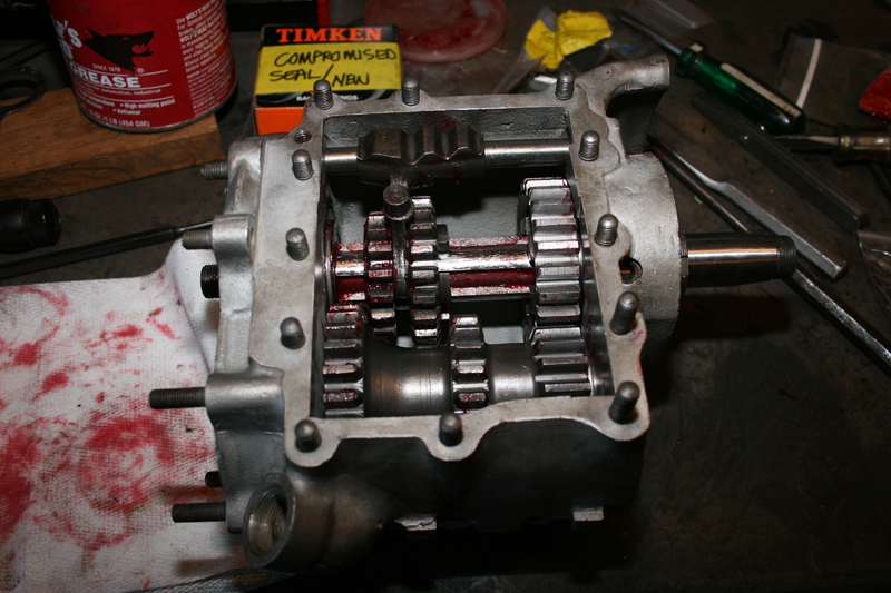
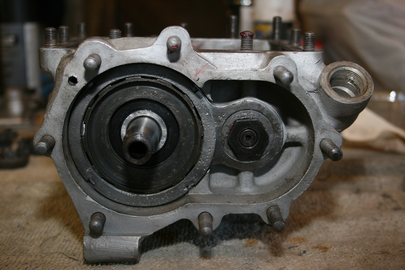
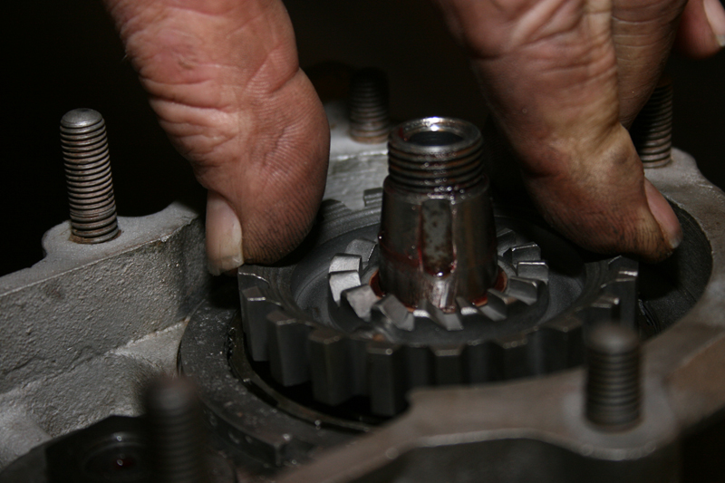
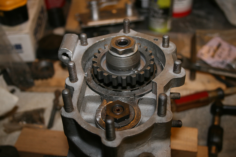
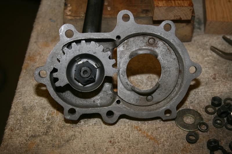
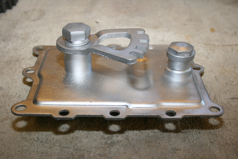
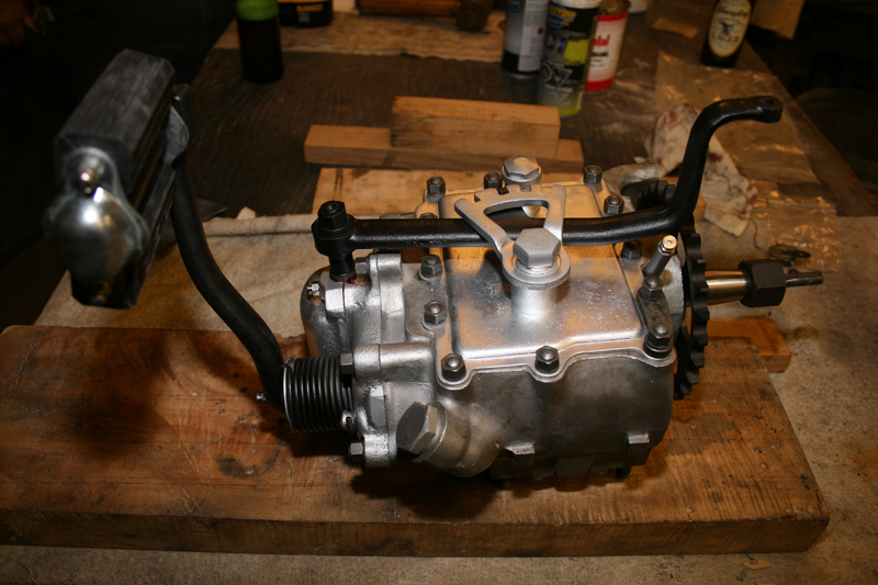
We have already gained the support of many of the top compaines in the vintage motorcycle industry. If you would like to see your company’s logo included not only on the motorcycle, but also on every article, please contact me directly to learn more about our marketing campaign and advertising opportunities. EMAIL
|
|
|||
|
|
|
||
|
|
|
|
|
|
|
|
|
|
|
|
|
|
|
|
|
|
|
|
Biker’s Choice TWIN-POWER Ignition Tech
By Robin Technologies |

I recently rambled about never giving up. This tech is an example in not giving up, and looking for opportunities for success. James Simonelli recently went to work for Biker’s Choice and it’s a company constantly looking for opportunities to succeed. They continue to expand and James is working hard on the Twin Power line of products.
I built this bike a few years ago and enjoyed each element of the build. It was my first opportunity to work with Black Bike Wheels and installed the new 23s at the time. I also worked with Rick Krost and the Paughco team, who were building his US Choppers frames and several components. I also worked with Chica for the first time to build my rear fender. This bike slipped together like a dream.

I was digging the old board track notion from the ‘20s, although I wasn’t the first. Arlen Ness built vintage-styled bikes with sidecars around Sportster drivetrains. The master, Don Hotop build a Silent Gray Fellow more refined than any the Davidson and Harley team built — it was beautiful. The Shadley brothers built another example with a sidecar, which I proudly featured recently.
I was just one in a long line of masterful Hamster builders to take on the challenge. When the bike was completed and I slipped the key into Phil’s Speed Shop ignition box and fired it to life, it purred like a kitten. It was a beautiful thing and I appreciated all the help and guidance slipped my way to see this project through to fruition, including the hand-tooled seat by Glen Priddle in Australia. Some of my welds were not handsome, but I was proud to see this puppy finished, and then I went for a ride.
My first challenge was the handling and the two, seemingly giant Black Bike spoked 23-inch wheels and Avon Tyres. It felt odd, but then it popped and coughed at just about 30 mph and I thought it had to be jetting. I carefully tuned and ran an S&S super E for the classic styling and shorter reach sticking out the left side of the bike.
That’s one of the distinct reasons for a Crazy Horse, now American V-Plus engine. It fit in the realm of making a bike look truly old, especially with the carb leaning out between the cylinders on the left, like old flatheads. No matter how I jetted it, it wouldn’t run past 30 mph. Ultimately, I changed the carb for a Mikuni, and I switched out the original Crazy Horse Ignition for a reliable Compu-Fire. I switched coils. I changed the exhaust by removing the muffler. Nothing changed how it ran, and I moved on to the next project.

But obviously it bugged me and recently, when James pointed out the new Twin Power ignition product from Biker’s Choice and suggested an install, I jumped at one more chance to make this beauty come to life. James suggested I install it with Primo-Rivera advance weights, although Twin Power sells a kit.

“Try it in the dual fire mode,” James suggested. “You’ll like the exhaust note and the old school thumping idle.”
Back to the initial problem, I heard strange rumors regarding Crazy Horse engines, and struggles to make them run. John White bought a bunch of the Bottlecap engines when the Indian effort failed in Morgan Hill, California. With the engines in hand, he started Crazy Horse Engines. He was a big construction guy and hoped to build something from the stylized engines, and I agreed with his philosophy. The engines were magnificent, classic, 100-inch, and different.
The company is now American V-Plus and Irma Martin, out of Auburn, Washington, owns it. She is working with Frank Aliano to reintroduce these puppies to the aftermarket and custom world.
As a rider, Frank spent over ten years racing motorcycles in all types of environments, including motorcross, cross-country, scrambles, enduro, hill climb, TT, flat track, ice, and drag racing. As a builder, Frank’s custom and high power creations continue to be trophy winners around the country, with several featured in national magazines.
As a designer, Frank spent decades in engineering, fabrication, machining and product development for Indian Motorcycles, American Quantum Cycles, Big Dog Motorcycles, A&A Performance, Double Services, and more.

Frank designed the billet system to plug more tuneable and flexible Evo ignition systems onto a Crazy Horse and now V-Plus engine. I reached out to Frank, because my investigation steered me to Micah McCloskey and then to Keith Ruxton, who designed the Worlds Fastest motorcycle engines in 1990, two Shovelheads built by Micah. They took the Easyriders streamliner to 321 mph and the record for 16 years. I was a member of the team.
Keith suggested, since I have switched out the carb and ignition, that the breather gear was out of time. “It could be flooding the engine with oil and causing it to fail,” Keith said. And so I dug in during the process of switching out the ignition system to Biker’s Choice Twin Power.

The Twin Power electronic ignition from Biker’s Choice fits ‘70 – ‘99 Big Twin models and ‘71 – ‘03. The unit is entirely self-contained and fits under the original points cover. It can be wired single- or dual-fire, and the built-in timing light allows for easy timing.
Front to rear timing is accurate to 1-2 degrees. It is delivered with a one-year manufacturer’s limited warranty, and they are made in the USA.

Twin Power coils are high-quality direct fit with at least 20% more voltage than stock.
These coils improve starting, stop high-speed misfires, and increase mileage and overall performance.
They are available in black or chrome and carry a one-year manufacturer’s warranty.

I went to work digging into the cam cover of the V-Plus 100-inch engine. I removed the point cover, hand-engraved by Heather New in Canada, with the 5-Ball Racing mascot, and then I removed the Compu-Fire ignition system, the ignition cap and the first level of cam cover. Frank coached me on removing the final billet aluminum cover.


“You may not need to back off the pushrods,” Frank said, but I ended up backing them off for a couple of reasons, including ease of replacing the cap. It can be a bastard if you don’t.

“This plate has a gasket and is held in place with steel dowel pins,” Frank said and he was right. “Take a claw hammer and install a quarter/20 bolt with a couple of washers into the plate. Use the threaded hole closest to the cam. With the claw hammer, leverage against the cam and hook the bolt.”

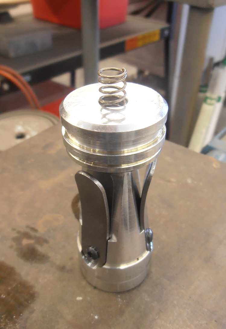

I readjusted the valves and looked for top dead center on the front cylinder with a massive tie-wrap. The tie-wrap cannot damage the sparkplug threads or any internal parts. Dominick, another master builder here in LA, suggested the tie-wrap.

“Once you have it at TDC, back it down 7/16-inch for about 30 degrees before top dead center, and your timing mark should show in the timing hole,” Dominick said. He was dead right. Worked like a champ. I grabbed a silver felt pen and was able to make marks to indicate TDC and 7/16-inch down. The timing mark popped right into the hole and I centered it by jacking up the bike and using the massive Black Bike wheel to move the engine in 4th gear.


Here are the Twin Power T/R #21-6500 ignition guidelines. They wanted me to rotate the motor until the front cylinder showed the fully advanced mark in the center of the timing hole, during the front cylinder compression stroke. Note: The compression stroke is evident when the both front valves are closed and you can rotate the pushrods with your fingers.
I installed the new ignition, keeping the rotor index hole in line with the light on the ignition, basically at 9:00. This system automatically runs in the single- or dual-fire mode, depending on how you wire the coil or coils. If it’s not in the 9:00 position, you’re on the wrong compression stroke. Rotate the engine again.

James recommended the dual-fire mode so I wired the Twin Power mini coil with the red wire heading to one lead and the black and white wires going to the other lead (it doesn’t matter which lead you chose on these coils). For single-fire coils, you need to run your hot wire and the red wire from the ignition system to the positive side of the coil, the white wire to one coil and finally, the black wire to the other coil.

This mini coil will afford more cooling space around it while it’s stashed between the heads. This coil doesn’t indicate a positive or negative lead position.

I ran the gray tube insulated wires out of the bottom of the cone cover and basically around the engine and up to the coil between the heads where many coils are located. I wish the insulation was black, and in hindsight I would have run shrink tubing over the gray sleeve for additional protection. I ended up extending the wires about a foot.
I also soldered a length of 14- or 16-gauge wire to pull the new wires through my existing loom. It worked like a champ to hide the new wires. I extended the wires, soldered them in place, using the Frank Kaisler soldering tool and his system for connecting wires, which can be a pain in the ass. He basically cuts and strips his wires and feeds one into the other for a direct connection, which also does not cause a lump in the wiring. It’s almost like shoving a key into a lock and it sometimes takes some maneuvering. That’s where his handy-dandy tool comes in.

Don’t forget to install the hot wire from your ignition switch to the hot side of the coil. You will need that power. I installed a new Twin Power Lithium Ion Battery while I was at it. What an amazing puppy.

This battery fit like it was meant to be. Most of these Twin Power Lithium Ion batteries were designed for stock applications, but we found just the right one for my situation.
Note: Use this ignition system with 3 to 5-Ohm coils.


After the coil was wired and actually before I completely installed the Twin Power ignition system, I installed the magnificent Rivera/Primo mechanical advance weights. I lubed the weight axles with some engine oil and slipped them into place over the cam and then slipped the billet aluminum rotor in place with timing magnets embedded into the cylinder. Be careful, the rotor only fits over the stem in one way. Note the position of the flat.


I repositioned the ignition plate and turned on the ignition switch. The red LED light lit up, and with a right angle punch I was able to push the rotor into the advanced position. It only moved about 20 degrees, if that. The light came on, indicating power to the coil and the ignition system. The key is to rotate the rotor counter-clockwise to the fully advanced position and have the light go out. As soon as you release the rotor, the light should come back on.
I always shoot for the exact link. I want it to light up at the exact point that the rotor moves. The coil and the spark plug fires the moment the LED light shuts off.
The timing procedure is exactly the same for both single- and dual-fire operations. The front and rear cylinders are internally timed and accurate to 1 degree.

That’s when life got interesting. The Redhead loaded up my 5-gallon gas can with premium and I poured a couple of cups in the tank and turned on the petcock. Nothing. I monkeyed with the carb. Nothing. Sometimes there can be a vacuum. I almost filled the tanks; still, nothing passed through the clear glass filter. I started at the carb and removed the line. Still nothing. I removed the line to the brass, inline petcock. No joy.
I could even looked down the mouth of the petcock and saw the large ball valve. I could see it turn and open. Nothing. If it had worked, my face would have been covered in gas. Then I attempted to remove the petcock.

I moved a large crescent wrench into position to back up turning the brass petcock and was immediately sprayed with gas. It was one of those strange moments in the life of a mechanic. Sure, it was a pain in the ass, but it always seems that stuff shows up at just the right time. The trick was to get all the fuel out of the tank so I could replace the split line, plus the petcock was clogged.

With the Redhead wearing protective purple gloves, we maneuvered large old fuel lines, funnels and the gas can to carefully remove all the fuel. I replace the split line (I have never, ever seen a line split like that). We removed the petcock and discovered what appeared to be a glazed layer above the ball valve. The redhead cleared it out with a short piece of brass rod and the fuel delivery system was replaced and fuel added. The 5-Ball factory racer fired right to life.
I spoke to Keith Ruxton the day before, and he told me that top end breathing engines, especially high performance engines don’t need breather valves, or even reed valves. I started looking at fuel delivery from the gas tank, which makes a lot of sense. I need to check to see that my fuel line will deliver 16 ounces of fuel in one minute, according to Dr. Ruxton. I removed the fuel line from the carb, stuck it in a measuring cup, checked my watch and turned on the petcock. It filled it to the 16-ounce mark in about 20 seconds. It wasn’t fuel delivery. So, I’m still not sure if my sputtering problem is solved.

I noticed one more item that needed to be addressed. When tightening the advance bolt, the rotator rubbed against the ignition plate, which would mess with the advance weight mechanism. First I took out the plate, because this cone was removable and if the Allens were loose it shifted around. I loosened them, shifted the system and retightened them. It was substantially better, but not perfect. This wouldn’t happen with a stock cone motor.
“The weights and the rotor have to be completely free to be able to advance,” said Ben Kudon, the Executive Director of Rivera-Primo

I reached out to James. “Here’s what you can do to Auto Advance units. Put a drop of blue Loctite on the advancer bolt and do not over-tighten. Spin the motor without the ignition in place and watch the rotation. If it is eccentric, take a small punch and give a tap on the flat of the hex head screw that will shift it to best center it, until it runs true. Please let me know, nothing should need to be modified. Occasionally, a shim is needed between the advance unit and the cam to shift the mechanism outward.”

“I am not familiar with the Indian cam cover, might be a little different from H-D. Does the plate fit nicely and rotate easily in the recess or is it tight? If this is tight, you may have to slightly sand or file the plate O.D.” That’s what I did until the rotor was centered. I also noticed the hex rubbing on the gasket. Again, this wouldn’t happen in stock applications. I cut a hole in the gasket and rotated the gasket to allow the 5-Ball Racing cap to set out slightly more. Done deal. James also suggest thin washers under the stand-outs, which would accomplish the same thing.

I took the bike for a ride. Over and over it fired right to life and hummed, but again is sputtered. I called Phil at Phil’s Speed shop late at night. He was still working. “It could be the cam timing,” said Phil. “They may have switched the gear for a better pinion shaft mesh and since there is no direct key-way to align the cam, it could have shifted.”
I’ll pull the cam today and take it to Bennitt’s Performance or Branch Flowmetrics to have it checked. Never give up!

Biker’s Choice
Paughco
Rivera/Primo
Black Bike Wheels
Chica
US Choppers
Rick@USChoppers.com
Phil’s Speed Shop
941 West Collins, Orange CA 92867
Appointment (714) 771-6727
Avon Tyres
New Line Engraving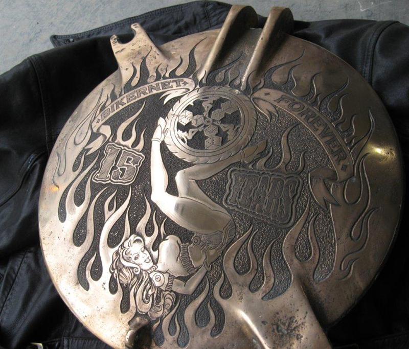
The Amazing SHRUNKEN FXR Updated
By Robin Technologies |

Once upon a time there was a bike built called the Shrunken FXR. Keith “Bandit” Ball, of Bikernet and other assorted fame, built it. By a stroke of good fortune the bike became mine through the generosity and trust of Keith Ball.
This bike was my daily commuter for a handful of years. It was and is always a challenge and a ton of fun navigating the streets and freeways of Los Angeles on two wheels and especially on a custom built motorcycle.

I decided it was time to update the look of the bike as well as do some fine-tuning of a few mechanical items I wanted to switch up a bit. Below is a brief summary of what was done, again primarily with the help of friends and some extra cash from my Pops to help get it all finished up proper.

First I replaced the front fork tubes with new fork tubes made by Forking by Frank. Styles have changes, so I installed new handlebars, 10-inch baby apes mated to Black Boyd Motor Co. risers.

I work at the magnificent ARCH motorcycle company and LA Chop Rods, so natch; I installed Black Anodized hand controls by ISR purchased. They are absolutely the best and contain the mechanical Bandit approved styling.

I replaced the mirrors with 2-inch Blind spot jobs by CRG (Small and work great). We
Powder-coated the classic Performance machine wheels black (Thanks to Custom Metal Finishing in Gardena CA, who handle the high-end ARCH motorcycle extreme perfectionist coating).


We manufactured a new Shift arm and Brake arm to improve function. Ryan Boyd, Boyd Motor Co./Arch Motorcycle, is a master machinist and engineer. He configured then machined these components to enhance the rear brake functions, and it now works like a charm, plus it improved shifting dramatically.
We replaced the pegs with something sport bike like and again Ryan stepped up to design and machine one-off mounting bracket adaptors.

We reworked the exhaust basically back to the original first version, added BBQ paint and LA County Chop Rods baffles.
These upgrades, in addition to the rear shocks by Progressive and my comfy Saddlemen seat make the Shrunken FXR road ready and looking fresh for 2016.

Me owning this bike and updating would not be possible without the help and kindness of the following wonderful humans beings: Keith “Bandit” Ball, Dr. Ladd Terry, Gard Hollinger, Ryan Boyd, Jose Laguna, Saddlemen, L.A. County Chop rods, Custom Metal Finishing, Boyd Motor Co., Frank’s maintenance and engineering.

Here’s a link to the original feature, if you search the Shrunken FXR on Bikernet, you’ll find all the build articles: http://www.bikernet.com/pages/Amazing_Shrunken_FXRThe_Full_Feature.aspx
–Buster Cates
The Magnificent ARCH motorcycle factory
LA Chop Rods
Saddlemen
BDL
Progressive Suspension
Rebirth of an American Classic: Case Repairs
By Robin Technologies |



|
|
|||
|
|
|||
|
|
|||
|
|
|
Rebirth of an American Classic: The Build Begins
By Robin Technologies |

|
|
|||
|
|
|||
|
|
|||
|
|
