Doug Coffey’s RetroMod Panhead Part 1
By Robin Technologies |


Other than the missing sidecar sidecar loops, it has a strong resemblance to a 1957 straight leg rigid frame. Exactly what I wanted.
Mudflap Girl FXR Part 13 New Paint and More
By Robin Technologies |
Here’s the link to Part 12: http://www.bikernet.com/pages/Mudflap_Girl_FXR_Part_12She_meets_SS.aspx

Okay, so my Mudflap Girl FXR was running fine and I enjoyed every ride with the bare chassis, but I got a hair to treat the frame and powder coat some parts, but the corrosion treatment made the frame look almost black, and I didn’t want to build another black motorcycle.


I also had some tech obligations. I needed to test the new Centramatic wheel balancers. I needed to install new Spitfire rocker axles in the girders and tack weld them into place. Then the bros at Digital Dawg contacted us and told us about their new keyless ignition. Suddenly I was inspired. I had installed a marine ignition switch in the backbone of the frame, and Saddlemen carefully made me a seat that fit, but reaching in to install the key was a pain in the ass. I started to work with Bruce McKinley from Digital Dawg, and the keyless system made more and more sense.


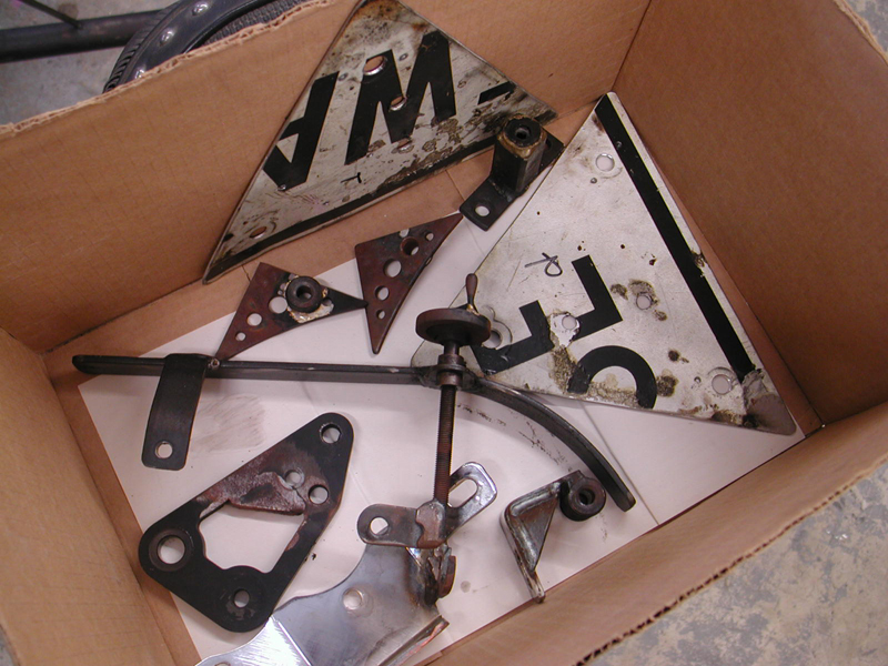
One day, under the spicy effects from drinking RedBall Whiskey, I decided to tear the bike down to the ground, finish the final TIG welds, and then powder coat the frame and Spitfire Girder front end. I tore the whole damn thing to the ground, and then discovered that I still needed to build a front fender.


For some reason that seemed a daunting project, but ultimately I cut a slice of Bare Knuckles heavy-duty fender blank and went to work. With the help of our certified welder, and master metal fabricator, Tobey, we came up with the perfect fender.

I cut and shaped the fender brackets and tacked them into place. He performed all the final welds. Then all the parts were shipped to Worco Powder for heavy silver and asphalt satin black.
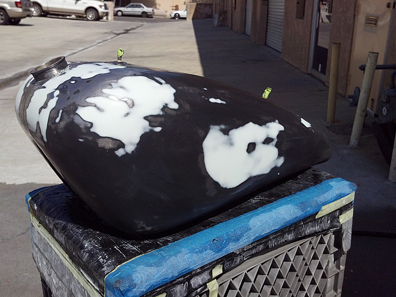

I hauled the tank to Chris Morrison in Harbor City to force the stretched Biker’s Choice flat black tank to match the powder, which he did masterfully. Then George, the Wild Brush put the final touches on all the black components with some simple matching silver pinstriping.


It was time finally, as the rainy season began to subside, to make this Girl run once more. Bruce Tessmer from S&S suggested I install a new Hi-4 single-fire ignition from Crane, along with their all powerful single-fire coil. There was nothing to it, and setting the timing was a breeze.


I pulled the plugs and the front intake pushrod tube clip. I rotated the engine over until the front intake began to close, then started to stare in the timing hole until the TDC slot appeared. I centered the slot carefully, rotated the ignition plate until the light went out, and presto, it was timed. The instructions called for an additional five degrees for electric start bikes, so I followed the instructions.


I also decided on a slight cosmetic change to the grips and pegs, and the new Contrast Cut Performance machine pegs and grips did the detail trick. I avoided chrome like the plaque, for a tough hot rod approach. I think it worked with the Metalsport Foose designed wheels and rotors.


John Reed made a comment to me about falling in love with a motorcycle, and I told him I was always in love with the bike I was building. This Mudflab Girl has touched a unique cord with me, and I’m not sure I can explain it. It’s absolutely the most comfortable, tall-guy fit bike I’ve ever built. I’ve tried to study every aspect of this machine and refine every element from the suspension to the electronics, and it’s still a work in progress. But there is something about this machine. It speaks to me, it fits, and it handles well for a chopper.

I called Bruce from Digital Dawg to discuss their keyless installation, and he informed me of a slight glitch. These systems are designed to slip neatly into any stock bike configuration, but nothing about my bike was stock. “You must have a kill switch,” Bruce said. “Most guys have a kill switch on the bars.”


He sent me a very cool kill button, and it worked perfectly to replace my old ignition switch in the backbone of the frame. This became a golden opportunity. I’ve built a lot of custom bikes, and few had kill switches. Like chain guards, kill switches are almost a Code of the West factor. If you need to kill your motor in an emergency situation, you don’t need to be hunting for that super-cool hidden ignition switch.

I followed the Digital Dawg directions and wired the system into my circuit. It works like a champ and is clean as a whistle.

Centramatic
This is one of those smoke and mirrors products that works. It’s like the guy in the seedy bar who hands you a small tainted bottle of liquid and swears that it will double your gas mileage. Don’t get me wrong, some of this shit works. Remember the guys who sold black rubber snakes or long tubes of solid rubber. If you installed them in your handlebars they would reduce vibration significantly. They may work, but they lack the obvious cool factor, and installation was a bear.


I watched the Centramatic youtube video around these puppies and was immediately impressed. I took a set of the stainless steel balancers to my local bike shop and asked if they would install them. The shop, Bennett’s Performance, is not a high-end chopper fab shop. It’s more of a performance, tough city streets, Sons of Anarchy style shop, but none of the customers would step up and install these puppies around their big buck Performance Machine custom rotors, or have them interfere with their brand new Chip Foose designed Metalsport billet wheels.


Centramatic On Board Continuous Wheel and Tire Balancers are a proven life cycle cost solution designed to smooth your ride and extend tire life with a unique “On-Board” balancing system for steer, drive and trailer axles for light duty and heavy trucks.
I actually believe Centramatic balancers would be perfect for Kendon Trailers. They manufacturer the same wheel and tire balance technology for Honda Goldwing, Harley-Davidson and Victory motorcycles.

• Increased Tire Life 35%-50%
• Reduced Vibration
• Dramatically Improved Ride
• 8%-10% Lower Tire Temp
For orders outside the United States, please call 800-523-8473 or e-mail us for shipping.
Not Sure Which Balancer Is Right For You?
To better serve you, E-mail us with the Year, Make, Model, Wheel Size, Number of Bolt Holes and Size of the Bolt Circle.
Click Here To E-mail: info@centramatic.com
The company describes the Centramatic product as a simple solution. Weights in Centramatic’s aluminum balancing ring move opposite of out-of-balance points with wheel rotation by centrifugal force, at any speed. The wheel is dynamically and statically balanced at all times. Old-fashioned lead weights are attached and can’t move or adjust to changing elements within the wheel system.
Large commercial fleets consistently see increases in tire tread life up to 50% and eliminate truck tire hopping from out-of-balance wheels. When a vehicle is retired, the Centramatic Balancer can be transferred to the new vehicle. No obsolescence here! Satisfaction is assured with a 5-year, limited, nationwide warranty and a 30-day, no-questions- asked, money-back guarantee.

Centramatic has had the privilege of having their “On-Board” balancers tested and evaluated by two of the most respected research organizations in the country: Auburn University’s National Center for Asphalt Technology (NCAT) and Speed Measurement Laboratories, Inc. (SML). At NCAT’s facilities, the effects on tire mileage and cab vibration were evaluated. Since operating temperature is critical to the endurance life of a tire, SML assessed the validity of Centramatic’s ability to decrease this debilitating condition.

By Speed Measurement Laboratories
By Auburn University Program for Advanced Vehicle Evaluation (PAVE)
Out of Balance Pounding Force, Per MPH
Balanced Wheel Diagram
Since I was in the process of tearing my Mudflap Girl FXR down for paint, I decided to give Centramatic a shot. I was concerned about only one aspect of the installation, the caliper fitment, since the stainless steel backing material was .030-.032 thick, so the rotors would move and require new caliper spacing in some cases. “Brembo brakes are more flexible than many calipers,” said Tom Nolte from Centramatic.

Other than the calipers, I ran into just one problem. My new GMA front caliper touched the outside ring of the balancer, and I needed to relieve the corner for clearance.

Other than those two issues, they simply bolted on under my Metalsport rotors and I was good to go. They are available for Victory motorcycles from 2007 to 2013. Victory bikes with ABS will need their sensors adjusted. GoldWings with ABS are good to go.


It took a couple of weeks to finish other aspects of the bike, before I could go for a test ride. My Metalsport wheels were mounted with Avon Tyres at Larry Settle’s shop and balanced, but in this case, I wouldn’t need to glue lead weights to my custom wheels. I rode the bike for a couple of thousand miles, before I tore it down. It ran fine and I worked extensively with David Zelma at Progressive Suspension, and Paul Cavallo at Spitfire on the rear suspension and the Girder front end travel.


When I finally pulled the Mudflap Girl off the lift and rolled it into the street for a test ride, I was astounded. This is a rubbermounted custom motorcycle with extreme suspension capabilities, and I was determined to make this custom bike handle very well for rides to the Badlands. I was blown away by how smooth it rode.

I faced one issue. The bike started to lean-snap or backfire through the carb. I couldn’t figure it out, so I rode it to Bennett’s Performance, and Eric adjusted the low speed jet on the CV carb, and monkeyed with the timing to no avail. Frustrated, I called S&S, Crane, and Departure Bike Works. I’m rejetting the carb right now with a new Sportster main needle, a .048 low speed jet, and a new choke cable. Hopefully, that solves the problems. I’ll let you know.

This was a Trock modified CV carb. Last night I tore it to pieces and studied every aspect while scrambling through the manual. I put it back together, and it did exactly the same damn thing. Then I replaced the new Nology spark plug wires with standard Compu-Fire jobs—did the same thing. I replaced the Crane high-power coil with my old Compu-fire single fire ignition coil—same results.


So this morning I started making more calls. I ended up on a mission to see an old CCI employee, Kip Woodring, now parts guy at California Harley-Davidson. Kip always makes the extra effort to help you find what you need. Like a dipshit, I didn’t note the jet sizes when I tore the carb apart. Of course the jets I bought were the same as in the modified jets in the Trock Modified Carb, but I still needed to replace my broken choke cable, so I wasn’t forced to manually hold the damn thing open.


The Bikernet Code of the West calls for never giving up. That line-item is right at the top of the list. A jet is nothing but a chunk of machined brass with a metered hole drilled in it, and mine needed to be larger. I dug through the official Bikernet dinky drill container, and was missing the finest of fine bits. I called the esteemed Bikernet Performance Editor, Ray C. Wheeler and he suggested a late-night run to Home Depot.


Sounded good, but I had one more option to try in the shop, my torch cleaner round files. I’ve had this set of cleaners for about 45 years. They’ve been kicked around the shop ever since I purchased my first set of Victor torches. I tried the smallest old bent and mangled tool. The non-abrasive end of the tool, just barely fit into the jet hole, but it did fit, and I started working the file back and forth until I could insert the entire body of the file through the tiny hole. I opened the hole from .019 to about .022 diameter. Chris, from Crane said the idle adjustment should be about two to three turns out. Lee Clemens confirmed three turns.

I ended up with a smooth idle at about two turns, and it quite lean-snapping. Tomorrow I ride, and we see if the fix is real. Hang on for the next episode with my grandson, and his Mudflap girl. He needs his baby to take him back and forth daily to Electric Tattoo on Balboa Island, where he works.
S&S
Bennett’s Performance
Wire Plus
JIMS
Spitfire

Doug Coffey’s RetroMod Panhead Part 2
By Robin Technologies |

Timbo’s ’64 FL Restoration (Part Two)
By Robin Technologies |

1964 was an interesting year for Harley. it was the last year of the 6-volt electrical system, and last year for the kick-start only. In 1965 they stepped up to 12-volt system and the first electric start and massive batteries started to appear. So let’s get started, I removed the primary, to my surprise it had a belt drive in it.


Someone wanted a step-up from the original chain drive, unfortunately it’s covered in oil that leaked from the main shaft seal and chain oiler that was never shut off. I might be able to save it with a healthy cleaning, we’ll talk about that later. After removing the primary drive and clutch, I thought the transmission would be a good place to start the restoration.

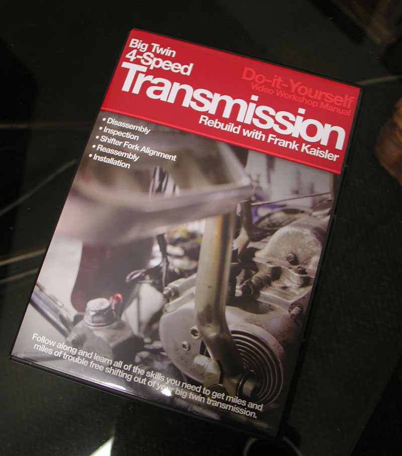
I did the research and found out all the parts I needed to rebuild the stock 4-speed transmission were available from J&P Cycle, and manufactured by JIMS. So off to the catalog I went. I ordered all the gaskets and seals I needed to rebuild it, except one, the main drive shaft seal (which was the worst one out of the bunch). According to the manual and other people I talked to, you need to invest $250 in the special tool from JIMS. It removes and installs that seal. However, I found an old friend (older than I) sorry Danny! LOL, who knew how to R&R the seal without the so called special tool, no big deal, according to him!


Be careful not to lose the gear shaft key for the sprocket. Also, there’s a small keeper key (looks like a flat L). It holds the sprocket far enough away from the seal, so it doesn’t ride on the seal. Keep it just in case. I later found out the new seal came with the keeper, but it’s better safe than sorry, if ya know what I mean.


There are some measurements you can take with feeler gauges for the shifter forks and spacers, refer to the manual.
Also you can check the timing shifter notches for alignment after the cover has been removed, also in the manual.

I actually ended up with two manuals, the original 1964 Harley service manual and a Clymer manual. Out of the two, I prefer the original service manual, it’s so easy to read and understand an idiot can follow it. Wait a minute! It’s also a good notion to pick up a parts manual for a variety of parts illustrations not found in service manuals.

For the serious rebuild the Wolfgang Panhead Restoration book, by Rick Schunk is an excellent guide. We were fortunate to have a low mileage transmission, and only a clean- up was required.

All the schematics are hand drawn in detail, very cool and definitely vintage. For the main shaft sprocket seal, I used the old school method my friend suggested, a slide hammer. Simply drill a couple of 5/32 holes in the seal, not too deep, about ¼-inch, screw in a sheet metal screw, and slam away!


It came out on the second slam of the hammer, YEAH! Installing the new one was just as simple, add a little Vaseline or WD40 to the outside of the seal and gently and evenly tap it in. I used a brass seal installer I had lying around, moving it back and forth on the seal so it doesn’t bind. Tap it down flush with the case, and your done. The JIMS tool insures that the seal is installed perfectly square into the case.
The rebuild kit came with all the gaskets and seals. There’s an O-ring seal in the kick-start shaft that rides between two brass bushings, be sure and replace it.

You can reach in with a dental pick or small screwdriver, and remove it without pounding out the bushings. The kit comes with new gasket for speedometer cable and neutral light indicator.

I polished up all the chrome it had and added a brass kick-start pedal, it looks great! Yeah, I know, not OEM pedal, but it looks cool and is pretty close to the era. I also ordered all new chrome case screws, the old ones were rusted, plus the chrome looks better anyway. I painted the inner timing cover and polished the out cap. You will find that almost all the transmission and engine cases are cadmium platted.


Lots of guys polish or chrome them, my customer wanted them to look as factory as possible. Here it is, the finished product. Not sure what I’ll tackle next, if you have any requests, let me know, I’ll be glad to accommodate. I’ll probably go right into the engine. That’s all for now, Tail Gunner out till next time.

Mudflap Girl FXR Part 12—She meets S&S
By Robin Technologies |
Here’s the link to Mudflap Girl Part 11: http://www.bikernet.com/pages/Mudflap_Girl_FXRs_part_11_The_First_Road_Test.aspx

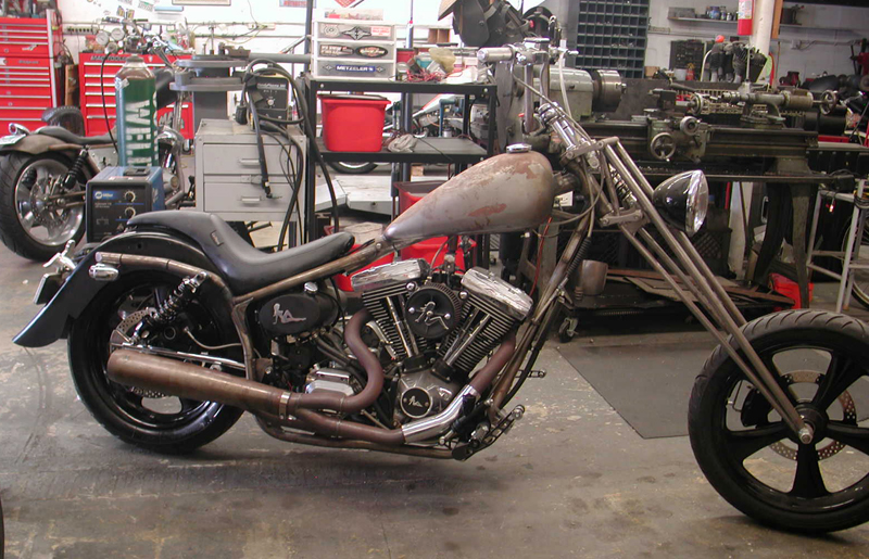
My son’s Mudflap Girl FXR is running and partially broken in. I even, finally, dialed in the Wire Plus Speedometer, and it’s working. I wish I knew what I was doing wrong, but that puppy works like a champ. I enjoy the tightness of the display and ease of installation. In that small cylindrical Wire Plus display, I get a speedo, a tach, trip gauge, neutral light, turn signal indicators, oil idiot light, and what else?

Okay, so it’s time to turn the Pro Street version of the Mudflap over to my son, Frank, but first we couldn’t leave the bone stock remanufactured 80-inch Evo engine alone. I reached out to S&S for a cam recommendation, and they recently built a relationship with Crane Cams.

Bruce recommended the following stock engine formula: S&S Super E carb, Crane Hi-4 ignition, S&S Cam and S&S easy-adjust pushrods, a Crane dual-fire coil, and the S&S 33-4250 breather and shim kit, for just enough pump to let this motor breathe.

I hauled the Mudflap beast on my Kendon tilt-up combo trailer to Bennett’s Performance, a very clean shop, next to Branch O’Keefe Flowmetrics, on Signal Hill. Eric Bennett, the boss, bought the Bikernet Hearse, immediately fired his girlfriend and started to cruise the backstreets of Long Beach. He traded his bagger for a Sons of Anarchy Dyna, and is about to turn the 88-inch twin cam into a 106-inch S&S night flier. His band, the Signal Hill Billies, transformed their usual light country western twang into dark blues. What the hell did I do? We will bring you reports on his engine transformation. I could swear the all-black lowered hearse smirks at me whenever I roll into his parking lot, but we won’t go there.

I pulled up the other day to find Frank’s Mudflap Girl on a lift center stage. No sooner did I enter the shop when Eric slipped out the back. A mysterious tech sauntered out of the engine room with long gray hair. “Don’t take my picture,” he said, “and don’t mention my name in the article.”

I’ve known him a long time. He’s an experienced Bonneville racer and a multiple-tour Vietnam vet, about my age. He’s only been married once, and is still married to the same woman. “I swear,” he said, “I’ve never pulled my military issue bayonet on my wife.”
I’ve been married five times and Eric three, and he just broke up with his long-time girlfriend. Maybe the graybeard tech with his twisted grin was trying to say something.

What the hell could I say? I set the box of parts on the lift and started to blow the dust off the fresh engine. Eric gave me a new cone gasket, seal, and a Torrington cam bearing, in case the fresh engine was fitted with a poor quality INA bearing—it was. I removed the pipes. The tech removed the plugs, and we jacked up the bike. He popped the pushrod covers and broke out the bolt cutters to remove the stock pushrods without removing the rocker boxes.

“I roll the engine over so the valves are closed when I cut the pushrods,” Graybeard said, “so the valves don’t slam shut when the pushrods snap.”

Then he removed the point cover, and the crane Hi-4 ignition plate. “There needs to be a washer under the fastener holding the Crane point breaker plate,” he barked.


Unfortunately, I had installed the Crane system and breaker plate—my bad. I thought about my fifth wife. He pulled the cone cover with a rare Trock tool, since the master is no longer with us.


With a couple of JIMS magnetic, or H-D lifter tools the lifters were held out of the way while he pulled the stock cam and checked the bearing.


Sure enough, it was an INA cam bearing with about half the rollers of the high quality Torrington cam bearings.


JIMS tools makes a handy cam bearing puller, which was installed, and swiftly, perfectly yanked the stock bearing free. Eric made specific machined aluminum drivers for installing new bearings, which were carefully tapped into place. After it was installed, he reached in to make sure the bearing spun free, with no binding.


Next, he aligned the timing marks on the pinion gear and set up the new S&S breather gear.


Steel breather gears have better dimensional stability than plastic gears. Embedded particles can damage the crankcase breather gear cavity. A screen provides better protection than a slotted gear, so small particles are prevented from entering the gear cavity, where they may damage the gears and oil pump.

The S&S steel gear with welded in screen with larger diameter holes provides improved air flow/oil scavenging from the flywheel cavity. Crankcase flywheel cavity vacuum and oil scavenging are further improved by optimized breather window timing. Breather oil trap scavenging is significantly improved by increased scavenge port duration. These improvements are the result of exhaustive research using digital sampling and data acquisition equipment.
This gear was the standard size for late 1977—‘99 Harley-Davidson big twins. Breather gear kits include breather gear and steel endplay shim kit.

With the new S&S breather gear installed, he started to adjust the endplay with a .120 shim. “That’s usually the one,” he said. As it turned out, we went with .110-inch shim after he checked the fitment with a straight edge. Then he performed a similar operation with the cam to check endplay. We discovered that a .055-inch thick shim was needed in addition to the existing flat shim. He dug around and found one, and we were set to test it with another JIMS special tool.

The S&S 510V bolt-in cam works well with stock or ported heads. The improved ramp design results in low valve train noise. It’s meant for engines up to 96 inches and with compression as high as 10:1. It’s designed to pull its best results in the mid to upper rpm range, 3000 to 5000 rpm.

It was time to set the cam timing with the pinion bearing and breather gear slots. Then the mystery tech cleaned some of the case threads with a tap. “Too much Loctite,” he said. He touched all the stock ¼-20 Allens with blue Loctite and installed the cone and torqued them to 110 inch-pounds. He installed the appropriate washer in my breaker plate, and then the timing plate.


Before he removed the Crane Hi-4 ignition plate, he scribed the plate and the case so the timing would be right where I placed it when everything was put back together—that is, if I didn’t fuck it up in the beginning.

I peeled the S&S quick-adjust pushrods out of their vacuum-packed container and shortened them for ease of placement. These S&S jobs were a breeze. He checked for all the needed pushrod gaskets, and we compared the pushrod lengths to use the short ones on intake valves and the long ones for the exhaust.

“I adjust them the old school way,” he said. “I make sure one intake lifter is at the top of its cycle, and then adjust the other. Then visa-versa.” He waited 20 minutes between adjusting valves for the stock lifters to bleed down, but while he waited, we started to install the pipes. “No time to lose.” He made sure each pushrod would spin after it bled down. In each case, he took the slack out of the pushrod and then turned it out four turns or 24.5 flats. Once he tightened the pushrod lock nuts, he would take the half flat out of the adjustment.

Here’s the Quickee Pushrod Supplement from S&S: To install S&S quickee pushrods, thread the jam nut off the threads towards the ball end and screw the adjuster into the pushrod tube until the threads disengage and the pushrod can be collapsed
When installed and adjusted, S&S Quickee Pushrods must have a minimum thread engagement of .500 or half an inch (Pushrod tube to Adjuster, not including the jam nut) or severe damage to the pushrod as well as your engine may occur.
When adjustment is complete, the jam nut must have full thread engagement with the adjuster screw. If you do not have full engagement, the pushrod is not correct for the application or position.
S&S Quickee Pushrods for S&S Shovelhead and all big twin engines contain two long and two short pushrods. All Sportster model and Harley-Davidson twin Cam 88 pushrodes are the same length.
We replaced the pushrod cover clips with another JIMS tool, and I finished installing the Spitfire brake master cylinder and pedal. Once together, we turned on the gas, hit the starter and it fired right to life. Our very experienced Vietnam vet tech let her warm up, adjusted the carb and quietly returned to the engine room to work on a twin cam engine build for a customer. It’s time for my son to pick up his bike and head for a paint shop or the hills.
S&S
Bennett’s Performance
Wire Plus
JIMS
Spitfire
Bennett’s Performance 2004 Dyna Build 106-Incher
By Robin Technologies |

Eric Bennett grabbed the shop door chain and hoisted the roll up door for the first time, in 2000. He started his mechanical career as a certified diesel mechanic with 60-weight always flowing through his blood stream. Finally, he gave into his entrepreneurial spirit and his desire to make motorcycles his life—he opened his own shop on Signal Hill. The rest is motorcycle history, much of it spent at the Bonneville Salt Flats with his dad, Bob.
He recently owned a modified twin cam FLH, but a customer made him a deal he couldn’t refuse, so he let it go. Then a deal on a Dyna surfaced and he made a quick move to snatch it. This time, he decided he would take it to the concrete and rebuild every aspect of the bike to be moderately fast, ultimately reliable, precise, and built with absolutely all the best mechanical intentions and components in mind. You get to see the 106-inch project unfold before your very eyes right here.

One of the benefits of running a service center in the largest city in Los Angeles County includes encountering every possible mechanical malady and the ability to research whatever solution might be necessary. Since LA is also the motorcycle media hub, he has constant opportunities to test anything new on the market. After working on Twin Cams since their introduction into the market in 1998, Eric has watched every configuration, modification, performance recipe, and model roll in and out of his shop.


With this build he could pour every lesson and improvement into his own ride. It started as a bone stock 2004, 88 cubic inch TwinCam. Eric could choose from any hot rod configuration in the world, but he chose to roll with a 106-inch kit from S&S and Branch re-tuned heads. He started the process by installing a JIMS Timken conversion into his left case and welding his crankpin into the S&S lower end after it was balanced.

“With superior S&S flywheels, I didn’t need to monkey with the cases,” Eric said.
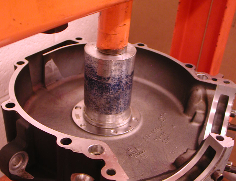
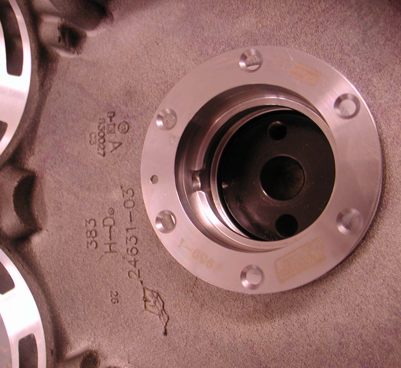
He bored the stock barrels from 3 ¾ to 3 7/8 inches and increased his stroke from 4 inches to 4.5. With JIMS tools he pressed in the JIMS race (using green Loctite) (9-59-1) while keeping his fixture perfectly flat and the hole in the race at 12 o’clock.


Using a JIMS fixture tool, he was able to drill guide holes in the case for Timken bearing and race oiling. The JIMS tool holds the drill and guides it. The drills are set to indicate the depth. Otherwise, he would need to use transfer punches and a milling machine. Then he used another JIMS tool to drill for the race fastener holes, and used tap guides to prevent misalignment.


“I’ve made tap guides for every size tap,” Eric said.


One of the benefits of the higher quality Timken lower end bearings is their ability to lock the lower-end into place.
“I have never seen a Timken bearing fail,” Eric said. Until recently Timken’s were used since 1957. “I’ve seen dozens of roller bearing failures!”
The cost saving shift to roller bearings started in 2003 during the 100th anniversary season. “The best Twin Cams were built in 2002,” Eric confirmed. “Better engines, still carbureted and with 1-inch axles for strength and stability.”


Eric used red Loctite on the race screws. He uses a tool for installing both Timken races at the same time. Kelly McKernnan, an amazing machinist out of Portland, Oregon, manufactured it.


The next phase included welding the S&S flywheels. Anytime Eric has a twin cam lower end out of a customer’s bike, he welds the crankpin in place with stainless TIG rod. It doesn’t create much heat and is not a structural weld; it just cements alignment and prevents shifting. He always checks the true after welding.

Next, he installed the Timken bearing by heating the race to expand it, and it slippped over the shaft easily. There is very little endplay in the shaft, just .001-.002-inch. Eric cinched down the top bearing with another JIMS tool, then pressed in the main seal and spacer with yet another JIMS tool.


At this point, we shifted to pressing the new S&S cam bearings into the new heavy-duty Screamin’ Eagle cam plate for hydraulic cam tensioners, but Eric chose to shift to an S&S gear drive system, so he blocked off the oil passages to the hydraulics.




He installed Torrington cam bearings in the right case prior to installing the new cams. His plan called for installing a D&D Bob Cat exhaust system, which is 20 pounds lighter than a stock exhaust. D&D pipes come bolted together with all spring clips, flanges, and heat shields in place. “They take like two minutes to install,” Eric said.


“It’s the easiest system I have ever installed,” Eric said. “It comes with the all the components needed and the heat shields in place. No shimming is necessary or egg shaping holes.”
Day 2


We took a break for the day and grabbed a beer. But the next day, Eric installed a heavy duty Harley-Davidson pinion shaft bearing kit using a JIMS pinion bearing tool and it was time to slip the cases together with Yamabond on the case edge, while applying assembly lube on the pinion shaft. The case bolts were torqued to 18-22 ft. lb.


“Don’t forget the new oil pump O-ring when installing the high flow H-D pump,” Eric pointed out. Eric has an engine-building quirk. He continually turns the engine over, while rolling through the build process, and constantly tests for changes. “I want to catch anything that might bind early on,” Eric said. We actually ran into a small glitch while installing the cam plate.


But first, he installed the oil pump return gears, and then the separation washer and the spring, before the feed gear. He bolted the cam plate in place with ¼ -20 fasteners torqued to 120-inch- pounds. He used guide pins to help align the oil pump, and turned the engine over while tightening the pump so it would seat itself properly. He tightened two oil pump bolts, then removed the guide pins, and then tightened the other two Allens.


While aligning the cam drive gear dots, he installed the cams and used red Loctite on the drive gear Allen bolts, but used assembly lube on the washer for more accurate torque values and to prevent the bolt from galling against the washer surface for a false torque reading.


As we wrapped up the operation for the day, Eric installed the lifter with the oil holes facing the cam cover, then the guide pins, caskets and covers. No more lifter stools.


Day 3

Eric sub-leased a portion of his Signal Hill building to Branch O’Keefe, perhaps the best head porting business in California. I don’t want to put down any performance heads, but Jerry Branch, who is now about 82, built a helluva business around head performance.

Here’s a description of their heads from the Branch-O’Keefe site:
This is where is all began. Branch-O’Keefe is known throughout the industry for legendary cylinder head modification service. Our extensive reworking of stock Harley-Davidson cylinder heads begins with removal of the stock valve seats and guides. Next, the combustion chambers are heliarc welded to add additional aluminum alloy in the combustion chamber and around the valve seats for re-machining.

The valve seat pockets are then machined for larger nickel-chrome valve seats, and the combustion chamber is cut from the stock low compression rectangular shape to the legendary Branch “bathtub” chamber. After cutting the combustion chamber, new oversize valve seats and performance-quality valve guides are installed to tighter than stock tolerances.

The heads then advance to the porting room where the ports are fully hand-ported, blended and polished to Branch’s exacting specifications as proven on the dyno and flow bench. The head’s gasket surface is machined an additional 0.050-inch, which raises compression slightly. Finishing up, new oversize intake and exhaust valves (hard chrome stainless steel with stellite tips, polished face) are installed in bigger seats with a machined race-quality valve job and then hand-lapped. New seals and a high quality high-lift radius spring kit complete the installation.

The Branch O’Keefe head components are damn impressive from the titanium upper collars to the single oval wire spring with more travel and a larger diameter spring material. They have developed heads for JIMS big inch motors that produce 132 horsepower and ft-lb of torque, at an absolutely stock reliability level, even on a B motor. So natch, Eric had John O’Keefe and his master right-hand man, Paul go through his heads. Actually they used a formula they call the Dave Thew head. It’s a nickname for a performance formula. Dave beat everyone with these Branch O’Keefe head configuration. I will outline the different formulas next week.


We started the day installing S&S pistons with wrist pins first, since the oil rings pass over the wrist pin holes. Seems odd, but it’s the nature of the short-skirted piston. “Actually it allows for more skirt on stroker motors and does away with stroker plates,” Eric said. “This piston configuration will keep a stroker running longer.” The oil ring must be positioned with the dimple in the wrist pin area in a particular location to prevent rotation. The S&S pistons use four-piece oil rings with a removable ring land.


Eric installed the bottom compression ring so that the opening faced the exhaust port area. “No gaskets are used on the bottom of the cylinders,” Eric said, “just O-rings.” He compressed the rings carefully, lubed the inside of the freshly bored cylinder and slid the cylinder into place. Then Eric spun the motor over to check for binding. “I can’t wait to hear the D&D pipe.”


Eric started to install the heads using Cometic gaskets. The heads were torqued to Cometic specs and then he set to installing the rocker boxes and the fasteners, which were torqued to 22 foot-pounds. He started from the inside and worked out. Then he slipped in the S&S Quickee-Install intake pushrods for maximum valve opening. “I run premium S&S lifters with travel limiters,” Eric said. “They become solids at high RPMs.”


He tightened each pushrod until the valve slipped off the seat, and then let it bleed down, for about 10 minutes. He backed off the adjustment until he could spin each pushrod (one at a time). Then he backed off just one complete turn or six flats.


These shots were taken before John O’Keefe came up with a crazy notion to machine Twin Cam cylinder fins in a round configuration. Eric was knocked out by the procedure and pulled his barrels for the process.


In the next episode, Eric will slip the beautiful 106-inch Twin Cam into the stock frame, and we will discuss JIMS tools, while replacing the inner primary bearings, the slightly modified Dyna D&D pipe, and then and the new Rivera Primo clutch, the S&S G carb, and a new S&S high flow air cleaners.


Sources:
Bennett’s Performance
S&S
JIMS

ACORN NUTS MEET THE MUDFLAP GIRL
By Robin Technologies |
|
||
Bikernet/Cycle Source Sweeps Build Part 7 Sponsored by Xpress
By Robin Technologies |
Hang on. We are two weeks away from running out to Vegas for Bikefest and pulling the winner of this most magnificent custom motorcycle, specifically built for Bikernet and Cycle Source fans, readers, and subscribers. You need to sign up, if you haven’t, or come to the Cashman Center in Vegas to grab a card and sign up for the drawing. You don’t need to be on site to win. After Bikefest, the scooter will return to Kustoms Inc. near Detroit, for final tuning and break-in before being shipped to the winner.

So here’s the update in a flash, after Bonneville, and heading smack dab against a Cycle Source Deadline. “I’m way behind,” said Chris Callen, the esteemed Editor da Emperor, in Chief, in Charge, in Trouble. This year has turned into the scrambling year. We are scrambling to finish projects; builders are scrambling to finish bikes. Chris scrambles every month to finish a magazine. It’s bananas.
The bike was displayed in Sturgis at the Broken Spoke. Then it returned to Grand Ledge, Michigan, down the street from Ron Finch, for final manufacturing and paint by the master of Chop Docs, Ron Harris, but let’s finish the pieces first.
“I kill batteries no matter what I do,” Gary Maurer said as we started to discuss the battery box. “When I carefully rubber-mount the bastards, they vibrated enough to rip the battery cables to shreds.” So now he puts a small rubber lining under the battery and bolts the unit down hard with Jules-made steel battery straps. He is now using Brail and Ballistic batteries with some luck. This is where I started to learn more manufacturing processes from Gary and Jules, again.
It’s interesting. I don’t consider myself a builder, and when I work with someone with the manufacturing knowledge of the Kustoms Inc. team, I know I’m just an enthusiast, not anywhere near a pro builder. This story contains a couple of fine examples of their expertise. The battery straps are easily bent after marking the position for the bend on the top corner edge of the battery. Jules made the hand bend with a solid bar of steel, and then noted the amount of metal used in the radius and worked it into the formula for the next bend so the strap fit the battery perfectly.
“There is a mathematical formula for this process,” Gary said. “You need to add or subtract material from the next bend, but we bend one side and then adjust the other.”
I also noted how perfectly the fender edge fit the line of the tire, since most fenders do not align with the tire radius. “We often scribe the radius of the tire on the fender and cut it to match perfectly,” Gary said.
He uses thick welder ground cable stock taped to the fender to give him the proper fender clearance. “Sometimes we use chunks of busted rear drive belts,” Gary said. “Sometimes, if need be, we can double the belt, or mesh the teeth for a slightly larger space.”
They break the chain to be as close to the center of the adjustment path as possible, with the engine, primary and transmission in place. Then they adjust the chain to be bowstring tight, and then they tape the spacing material to the tire and start mounting the fender.
This Bare Knuckles fender was bobbed and channeled on both sides by Jules. She often cuts with a plasma cutter, and then works the edge with Matabo grinder with flap wheels. Bare Knuckle fenders are made with solid, thick spun steel. They are as strong as a battleship hull and easy to work with. “Our plasma was toast,” Gary said, “so she used a high-speed cut-off wheel, then the Matabo and flap wheels.
I like the exhaust system he built with D&D components and a carbon fiber muffler. I asked how he held the components accurately together for tacking. “I start generally, but not always, with the muffler in place and move forward,” Gary said. “I hold the chunks in place with three fingers and tack them.” If his weld pulls away from the joint, he adds a small ball of rod to one piece, then holds them together, and heats the ball until it flows to the other tubing piece.
Note how Jules fashioned the lower fender mount to the frame so it acted as a battery strap mount and fender mount.
Then Gary built the sissy bar by hand-bending the steel rod. He machined each chunk of bar stock for the frame rails, and drilled them ½-inch so the rail would simply insert into the welded boss. Then he drilled and tapped them for setscrews. On the top, he welded a machined bung to the bar, and a drilled and tapped the bung to the fender, so the fastener simply slips through the sissy bar tab and screws into the solid bung on the fender.
With all the components tested and brushed with flapper wheels, Ron Finch stopped by and picked up the components for the trip to Ron Harris, a third generation paint and body shop guy. “I couldn’t touch a paint gun until I could bump a fender,” Ron said of his granddad. Back in the day, bodywork was hammered and filled with brazing and lead.
“My dad called Bondo Chinese lead,” Ron said. Then he ran down the Chop Docs custom paint process. From the photos, paintwork slides along like ironing an old pair of Levis (who the hell does that anymore?), but any top-notch painter has the talents of a concert violinist. It may look easy, but there’s a refined eye and level of perfection that turns any steel surface into a perfectly smooth piece of art.
As soon as Ron Finch dropped off the components and peeled out, Ron Harris cleaned the welds with a cookie wheel, and then scuffed all the surfaces with 80-grit for a world-class bonded protective coating. Initially, paint was used solely to protect a surface. Now it protects and adds the final illustrious finish.
Then he coated all the sheet metal surfaces with a filler Bondo skin coat and block-sanded the surfaces. This is where perfection and talent come into play. I’ve been there. I couldn’t Bondo a baby moon hubcap and make it look like new. There’s an eye for sanding just the right level of Bondo to capture the perfect slick surface.
He followed the Bondo coating with a skim coat of putty to capture imperfections, and then tested his eyes with various levels of Emory paper from 80-grit, to 150, to 320, so he can minimize his primer usage.
“I’ve been working with Stage 5 Coatings for two years,” Ron said.
Stage 5 Coatings was established in 2008 and is the newest and one of the fastest growing coatings suppliers in the United States. We are committed to selling jobber direct and establishing an exclusive territory for anyone that carries our lines. We strive to offer the best values available in the market. We are a small company that is personal and ethical. We build a personal working relationship with every customer, whether they are our largest or smallest. We believe when a customer buys from us, a partnership is formed, and is not just another customer. We have the industry experience to put ourselves in your shoes and understand the everyday struggles in the body shop business. From us to the jobber to manufacturing, we have the personal hands-on experience in all areas of the aftermarket coatings industry.
States with Stage 5 or Technico:
Michigan New York
Illinois Missouri
Texas Oklahoma
Wisconsin Oregon
California Arizona
Washington Georgia
Maryland Caribbean
Virginia
Ron is working with Ken Dudley on a line of Chop Docs candies. After he primed all the surfaces, he used a black spray bomb dusting to cause imperfections to surface. After any pits or surface maladies were dealt with, he water-sanded everything with 400 grit wet and dry, and then hand-sanded with 600 grit and finished off with Scotchbrite.
With the components hung in a booth, he primed them with two coats of sealer, and then hit them with the silver base coat and inner clear before taping off for the black pearl inlay. Then everything was cleared again and sanded with 600-grit.
This was Ron’s first attempt with green variegated leaf* using Mona Lisa glue to attach it to the paint surface. “It’s like a very thin, watered-down Elmer’s glue,” Ron said. “The leaf is so thin, it’s like dust in your hands.”
Once the leaf was glued into place and the area cleaned with a cotton ball or a brush, Ron hit it with another coat of inner clear, which locks the base down and leaves sort of a satin surface to adhere any art to, such as pin striping by John Harrow, who used a one-shot enamel sign paint called Kansas City Teal.
Now for the final six layers of gloss clear coats and 1500 grit wet sanding, followed by 3000 grit with water, and then buffing with polishing compound, finishing glaze, and spit shine. It’s Saturday, and by Monday, all the elements will be returned to Gary and Jules and Kustoms Inc. for final assembly. Ron volunteered to help. Unfortunately, he’s 140 miles away, but he drove out and spent all day, Sunday, helping with assembly. “It’s 80 percent there,” Ron said on his way home.
Speaking of volunteer efforts, this has been an amazing build with efforts from a variety of sources, all to create a bike we are giving away. No one made a dime off this puppy. It’s all American-made, and the whole gang pulled together to offer Bikernet and Cycle Source readers a shot at a world-class custom motorcycle—thanks. Chance of a lifetime, goddammit.
Dimensions: 5½” x 5½”


Xpress
http://mysmartcup.com/
Crazy Horse
http://www.crazyhorsemotorcycles.com/

Texas Bike Works
www.TexasBikeWorks.com

Kustoms Inc.
KustomsInc@hotmail.com

Chop Docs
www.Chopdocschoppers.com

3 Guyz
www.3Guyz.com

Accel
Accel-ignition.com

Fab Kevin
http://www.fabkevin.com/home.htm
.jpg)
Evil Engineering
www.evil-engineering.com
D&D Exhaust
http://www.danddexhaust.com/
Wire Plus
http://www.wire-plus.com/

Barnett
Barnettclutches.com

Rocking K Custom Leathers
howard.knight@montana.com
Rivera Primo
www.RiveraPrimoInc.com

Spectro Oils
www.Spectro-oils.com

Bell
www.moto@rcn.com

Metzeler Tires
www.metzelermoto.com
.jpg)
Hawg Halters

Handy Industries
www.HandyIndustries.com

Grip Ace
www.gripace.com
Biker’s Choice
www.bikerschoice.com
Aeromach
www.aeromachmfg.com

Ride Wright Wheels
www.ridewrightwheels.com

Biker Pros
www.BikerPros.com

Bare Knuckle Choppers
www.bareknucklechoppers.com

Rivera-Primo Brute II Install
By Robin Technologies |

We have a goofy Shovelhead in the Bikernet shop called the 1928 Shovelhead. It has 21-inch wheels front and rear in a Paughco rigid frame, but some 1928 elements were used, including the re-pop semi-flat sided tanks, the rear fender and perhaps the seat. The bike was conceived by Bandit the bastard, built by the crew at Rick Fairless’ Strokers Dallas, with the help of Randy Simpson who manufactured the handlebars.

The bike has contained a couple of hiccups and hasn’t been ridden much. Recently, one of Bandit’s friends needed a ride, so Bandit shipped this puppy to Washington. Richard Kransler installed new Avon tires and took it out for a spin. Unfortunately, the early Rivera-Primo belt, stuffed into the semi-stock inner primary, snapped and the 1984 Shovelhead was garaged. More recently, Richard concocted a deal with Bandit for a van in exchange for his Sturgis Shovel, and returned the 1928 Shovelhead to the headquarters, where the gang went to work on it.

With Richard’s info, and after consulting with Ben Kudon at Rivera-Primo, a plan was put into motion to make this wild puppy more rideable. We needed to add an oil filter, rerun the oil lines to reduce heat, fix the sumping problem, replace the primary drive, and then we discovered a loose valve seat, but we’ll get to that.


This is also a two-part tech. We first installed the Brute II Extreme Belt drive with a 1 ½-inch wide 11mm belt with electric start in the closed primary. Then we will install the most magnificent Rivera-Primo Pro Clutch. Since this is a jockey shift, it will be interesting to test both the stock clutch against a new clutch system that’s state of the art. We will forward all of our extensive reports directly to the boss and all Bikernet readers.

We discovered immediately that the front Brute II pulley was larger than the previous model, which was disappointing because it called for more clearance in the case, which weakened one of the primary fastener locations. Not a big deal, so we went to work with a pneumatic cut-off blade and emery wheels.

It’s critical to disconnect the battery, especially while working on the inside of any Shovelhead primary. It’s too easy to bump or pull on the starter solenoid, and you could lose a finger pronto. Fortunately, we have a selection of JIMS tools and pullers for this operation.

Here’s the fine print from Rivera-Primo: Primo Belt Drives are designed and engineered to correctly fit stock Harley-Davidson motorcycles. Aftermarket frames, primary covers, engine shafts, or clutch hubs may cause installation problems. Also bent frames, sagging motor mounts, worn transmission mounts, and other defects may cause shortened belt life due to incorrect pulley alignment.

If you have a stock system being replaced, here’s the dope: Remove the front pulley, chain, compensator and chain adjuster. Remove oil lines to primary and plug or clamp to prevent leakage. Cut the chain oiler hose 3 inches from the oil pump and permanently plug it. All belts must be run completely dry, without lubrication of any kind. Therefore, remove all oil from inside the primary covers.

The spacer behind the front pulley should be removed before installing the belt drive. This spacer may or may not be required to correctly align the pulleys. If a spacer is needed for alignment, various sizes are available from your local Primo-Rivera dealer (part number PX-1, is a package of various sizes).

We discovered a very tight belt. We had to carefully install the belt in the case first. Then the front pulley was installed onto the main shaft, but just slightly to afford us some flexibility with the clutch hub. We re-greased the bearing on the clutch hub and inside the clutch shell. With the handle of a plastic hammer, while prying it with a large screwdriver, we were able to drive the clutch shell over the hub with some gentle persuasion.

We tracked the belt, and installed the same spacer from the last system behind the engine pulley. With the bike jacked and the plugs pulled, we turned the engine over to test the running direction. We made sure to run the engine over in a forward direction. It’s not a bad idea to use a straight edge at first to make sure the pulleys have the proper spacing.


“Spacing the motor pulley outward will cause the belt to track towards the outer primary cover,” said Ben. “If spaced too far out, the belt will rub on the inside of the clutch shell.

Then we attempted to install the outer, aftermarket tin cover and discovered a significant problem. It rubbed against the clutch shell. So far, our inner primary clearance adjustments worked.

We were concerned about the tightness of the belt. It seemed severe to us, and to Bandit. According to the Brute II directions, the belt requires a minimum of ½-inch up and down play at the center of the belt, and up to ¾-inch. We barely encountered ¼-inch of tough play. “Free play is critical,” Ben said, but when Bandit questioned him, he muttered something about ¼-inch being okay, since the belt was so stiff.

The crew even considered replacing the system with a stock chain, to avoid issues. We took the system apart and studied each element, and investigated. I looked into a longer belt, or installing the earlier unit again, which had its benefits with the smaller engine pulley and tapered clutch shell that fit in the primary. We installed the belt again and tested the flex—still tight. We cut a hole in the tin primary, eliminated that problem and affording us tremendous venting. We live and breathe by the Optimist Creed, sort of code of the west. We are hoping once the belt settles in and warms, we will encounter additional flex and no stress on the engine and trans bearings.

“This is a much stronger, more technically advanced belt over the previous 14mm belt,” Ben assured me. We will give it a shot. Venting is a critical element. Primo recommends venting enclosed belt installations to allow cool air to circulate into and out of the primary case. This will keep heat expansion to a minimum and extend belt life.


Special Note: Big Twins from 1969 require a #16657 motor seal. Next we will install the new Pro-Clutch from Rivera Primo and test it, so we will be in and out of this primary case and reporting back on our findings.


In the meantime, we rerouted the oil lines, added an oil filter mount, and an oil pressure gauge for more capacity, cooling, and cleaner oil. We worked on the sumping problem, and then discovered that a valve seat was loose in the rear head. We pulled the heads and delivered them to Branch O’Keefe for repairs.

Our shop intern and overall handy-man, Kyle Olsen, our official Bikernet electrician, will test this bike. We are determined to make it a solid rider, and Kyle will bring us reports and handling complaints in the near future.


We modified the jockey shift and added the 5-Ball for easy shifting that’s out of the way of our thighs at stops.

And Bandit has a code, a good one. All bikes need rear chain guards, and this bike doesn’t have one. We will remedy that. Plus we have a brand new set of Nology plugs and plug wires to install. Hang on for the next report.

Timbo’s ’64 FL Restoration (Part One)
By Robin Technologies |

Not too long ago, my good friend Timbo approached me with a proposition, restore his 1964 Harley FL, I agreed. Problem was, it’s in a box, literally! So after a brief discussion on exactly what we wanted to do, how much it would cost and the possible value at the end of the rainbow, I started the Hard Ride back from Hell with the old ’64. I picked up the bike, basically a roller and all the boxes of parts that came with it. As you probably expected, this will be a frame up restoration as close to factory specs as I can get it.

There will be some minor changes, which I’ll talk about as we go along. First thing was to lay it all out and take inventory to see what was missing. After some research, I found replacing parts for the ’64 surprisingly easy thanks to J&P Cycle, Biker’s Choice, and the internet. I ordered the Vintage catalog J&P Cycle puts out and started researching parts I needed to replace.

I also found a local polishing company and chrome hardware supplier (needmorechrome.com) to make life easier. Tear down was a snap. Make sure you bag or box all your parts as you go and label what they are, and in some instances what order they go in. It’s not a bad idea to take lots of photographs for future reference. Sometimes a parts manual comes in handy.


After tear down, I started the fun stuff, going through each and every part, each nut and bolt and cleaning them. Some parts and hardware will not be salvageable, so you’ll have to replace them with either new, or good condition used. I found that there is a tons of vendors on line for just about everything you need. Buying new parts from the catalog is not always the best answer, especially if you’re on a budget like I am.


So shop around, do some research, you may be able to save as much as 50% sometimes. You will also need repair manuals and a few restoration guides like the one my friend Bandit sent me for reference from Wolfgang publishing, thanks Bandit. It has been very useful so far. This is the first of many articles on this restoration project. As the months progress, I’ll try and give you a detail look at what’s involved with a full-blown restoration.
Tail Gunner out for now, see ya next month!

