Bikernet West Bogged Down In Pheonix
By Robin Technologies |
| I knew it! The sonuvabitch couldn’t make it to the Badlands and back on that piece of shit. I knew it! The way Bandit mounted that tank was fucked from the beginning.
 I told him. Nuutboy told him. Harold Pontarelli told him. Shit, his 78-year-old mother told him. Did the big bastard listen? Nooo. So it jumped off the frame in Aspen, Colo., and landed in his lap.
 Yeah, they welded it up in Aspen with the help of Randy Aron from Cycle Visions in San Diego, and he limped into Sturgis, rode around the Badlands for the week and then the scoot was kidnapped from him by someone who knows what the fuck he’s doing, namely Paul Yaffe from Paul Yaffe Originals in Phoenix. Paul is working with Kyle of Independent Tanks, who hand makes steel tanks from heavy 16-gauge material. It’s about time someone grabbed that bike before it exploded into flames and scorched the ornery sonuvabitch.
 So we sent that fly-bitten claybrain to Phoenix for a welding lesson and instructions on how to properly mount a gas tank. If he wasn’t such a hasty-witted old fool, he would have put the bike together right the first time.
 Here are shots of the existing piece of shit with the new tanks recommended by Paul, who builds some of the most innovative bikes on the planet.

 Paul’s philosophy is to manufacture enough custom components to allow his customers to build something without doing a piece-meal job. “Instead of buying fenders from me that don’t fit the other guys’ frame properly and then mount a gas tank from so and so, and nothing fits properly, I want to give the customer half a chance to build a world-class custom on his own.” Paul’s positioning himself, unlike Bandit, to afford customers with frames, plus the fenders, tanks and billet components to match. Paul began his operation building LED taillight products. Unlike the slob who runs this joint, Paul is a young man of vast energy and talent who could not contain himself building bikes with existing components. He began building his own fenders, air cleaners, frames, etc. The young upstart with the flaming red hair does share one notion with Bandit: “If you’re going to build a new full-custom for a customer, I want the bike to be a reliable runner, of the newest technology, or how can you call it a new bike?” So all of Paul’s bikes are built with Harley-Davidson Twin Cam drive lines. “I use as much Harley stuff as possible,” Paul said. “Plus the factory is going crazy building more new accessories all the time. The selection is growing by leaps and bounds.” Damn, if I told that lunkhead Bandit once, I told him a thousand times, it’s time to move away from the Evolution shit into the real world of Twin Cams. But that motley-minded minnow is still out in the garage trying to put two Mikuni’s carbs on his ’48 Panhead. If you want to check true customs, built to ride, check Paul’s site http://www.paulyaffeorginals.com Finally, after much consternation, Bandit succumbed to one of Paul’s buddies, Kyle at Independent Gas Tanks. These are new, contoured tanks and here’s how ya do it right.
 Kyle has been building his own line of steel gas tanks for two years. Prior to ’98, he built tanks for Roger Borget for three years and before that he built Porsche 911 race cars. He won’t get near aluminum. “Not with the engine sizes that are bouncing around in these frames,” Kyle said. None of his creations are Mig welded, either. “I only Tig weld my tanks. I’m glad to work with builders and make suggestions.
 I’ve hand-built over 1,000 tanks for Harleys, and if told the brand frame, the stretch and rake, I usually know which tank works the best. I can go with one of my six to eight standard styles, or I can design something out of this world. I can make a bike blend into the crowd or stand out anywhere.” Kyle’s tanks come with mounting straps. Don’t just weld ’em on and go, though. “Depending on how the tank is designed to mount will depend on if the existing tabs will work immediately or need to be modified,” Paul said. In this case, he created some spacers to allow the tank to set on the frame perfectly to capture the look the big bastard wanted, then he cut the tabs and tacked them to the frame. Next he removed the tank and solid tacked the tabs. He put the tank back on and made sure everything was in place. These tanks are handmade and not manufactured with a jig, so no two tanks are alike.
 The tabs were finish welded and the tanks shipped to Harold Pontarelli for repaint. Paul welds everything with Tig because the Argon gas shield makes for a more controlled burn. It gives him better penetration and a less brittle weld than a Mig. Kyle had one other recommendation. He often gets calls from brothers requesting tanks after they have taken their frame to the powdercoater. Don’t do that. Make sure all the sheet metal is prepped and assembled before any finish work is undertaken. In fact, many builders ride scoots without paint for a hundred miles or so before tearing down for paint. Saves the headache, and makes for a much tighter custom.
 Of course the whole operation must have a photo finish. Two days before the Love Ride, the tank is floating into town via Harold and eight H-D Performance troopers. The bike is rumbling in on the back of Paul Yaffe’s custom trailer. The two will meet with Bandit in Woodland Hills for the install and road test for the parties to come that weekend. He doesn’t deserve this scoot. It should be mine. –Renegade |
| |
Bikernet West – Zebra’s Chop is in the Lead
By Robin Technologies |
In his sullen mood, he continues to assist his brother Agent Zebra, although some of the parts he’s now bolting on the Agent’s Paughco/Custom Chrome monster look suspiciously familiar. Could it have been an inside job? Could he need cash to pay the rent? Could another psycho girlfriend have taken him for more than his heart? –Snake
|
Sturgis Shovel Part 8
By Robin Technologies |
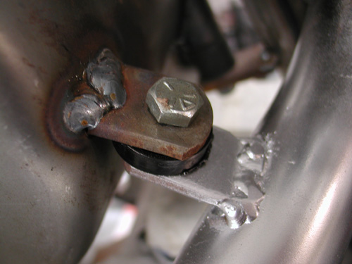
My first move began with a correction. I removed the exhaust pipe tab welded to the oil bag. The oilcan is rubber mounted, the exhaust pipe generated severe heat and the pipe system needs to be solidly mounted. It had to go. Actually Kent from Lucky Devil Metal Works in Houston tried not to mention the false move, but his frown gave it away. Or was it that question? “Is your rear pipe really mounted to the fuckin’ oil bag,” Kent said tentatively?
I discovered that the pipe exits the head close to the seat post and worked on a pipe connection there. There are a couple of rules in making pipes that I need to abide by. I needed to remove the pipe once in awhile, so I needed the pipe tab to be on the outside of the frame tab. Often mounting required slack, so I dug around for 1/16-inch washers to run between the tabs. That way when the fasteners are removed there’s some slack to pull the pipe free.
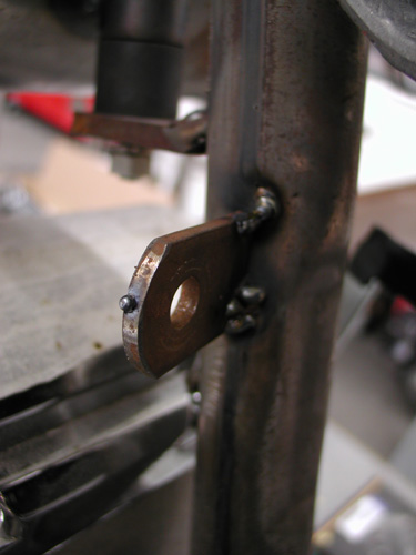
I worked with the pipe fully in place then tacked the seat post tab. Below is the tab tacked to the pipe. Then the tab welded in my shitty MIG welding fashion. I should slow down and clean the base metals more. I generally grind a bevel into the tabs for greater weld penetration. The welds are strong, just not handsome.
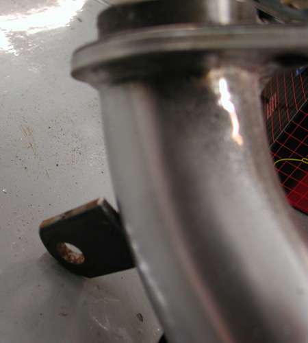
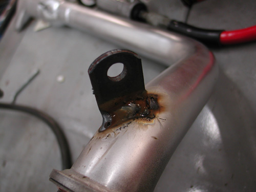

Next I needed to attach the Lucky Devil rear fender, align the rear wheel and cut the chain to fit. But first I needed to center the wheel in the frame, sorta. The custom Paughco frame is designed and manufactured to hold a belt pulley and a 180 Avon Tyre. That prevented me from measuring between the frame rails. I needed a straight line down the center of the frame backbone. It’s not incredibly accurate but close to draw a fabic or nylon line down the tube. Then with Doherty space kit and the seal spacers that came with the Custom Chrome aluminum and stainless spoke wheels, plus the Brembo brake caliper bracket, I aligned the wheel.
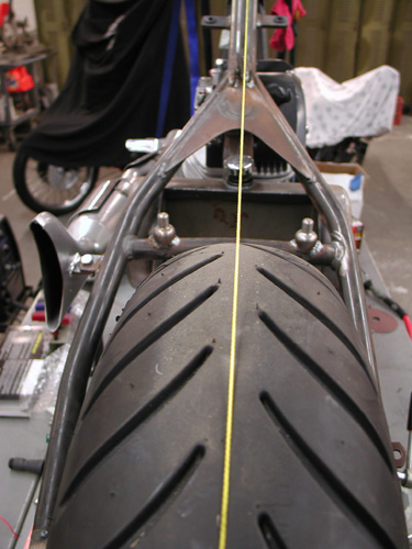
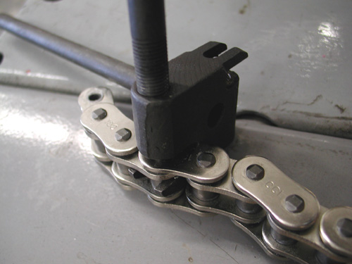
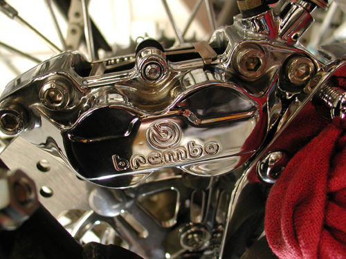
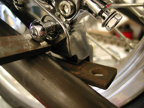
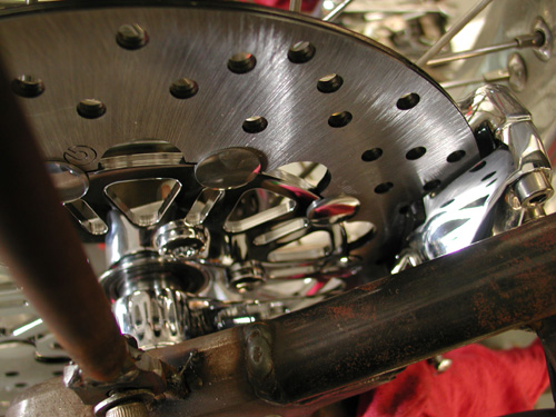

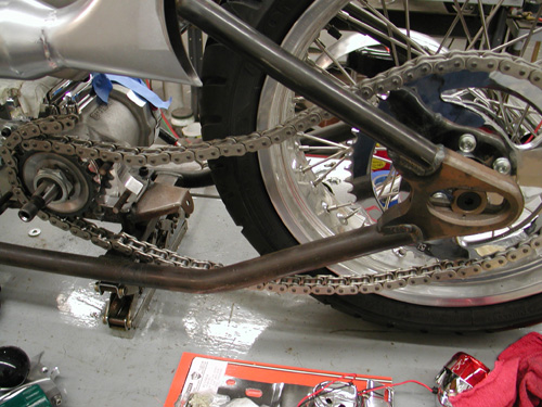
Before I cut the Rev Tech chain I installed the BDL Belt inner primary and pulled the engine and transmission into place which determined exact spacing. I know I covered this aspect somewhat a couple of chapters ago. There’s been some heavy drinking in the meantime, so if I lose track, it’s on Jack.
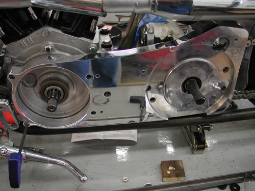
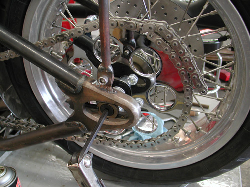
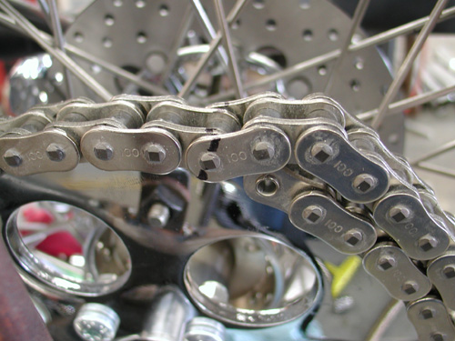

I centered the wheel in the chain adjustment slot to give me slack either way. Then I finally cut the chain with a JIMS tool.
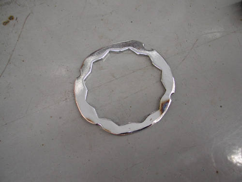
I spoke to a couple of guys about sprockets and was told that this contraption will hold a sprocket nut from coming loose better than simply Allen screws in the Custom Chrome sprocket. I may use it or not. Haven’t decided yet.

The reason this is altered is that it’s for a pulley and a different era. Add that to the fact that I flopped the dished sprocket over to space the chain away from the tire. That aspect worked perfectly.
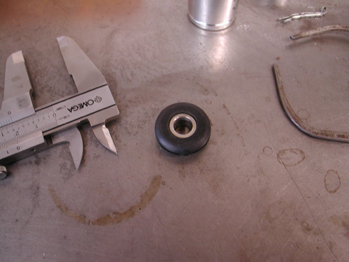
I decided that since the tank was rubber mounted and aluminum won’t flex as well as steel that I would attempt to rubber mount aspects of rear Luck Devil fender. Kent designed and handmade the fenders to match aspects of the XR 750 tank.
Cyril Huze sent me several grommets to work from and this pair are from some late model Sportster application. I measured the O.D. on the center portion and discovered that I needed ½-inch holes in the fender which I drilled after I had mocked up the fender in place, ground a clearance strip for the chain and stood back several times. Arlen Ness once told me that he used a chain wrapped over a tire to space a fender. I needed enough space for fasteners under the fender and some chain adjustment slack either way.
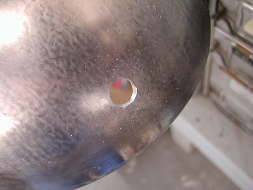
I moved the fender up and back, and side-to-side several times before making any hole-drilling marks. I was a nervous wreck. Ya don’t mess with the Devil’s fender. I finally drilled a half-inch hole, and smoothed the edges, in the bottom of the fender then at the crossover tube. I worked in the rubber with a dab of oil and bolted the bottom stainless bolt in place.
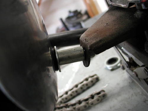
The Sportster grommets have metal inserts, which make them easier to install. With a couple of spacers in place the fastener held the center tab for tacking.
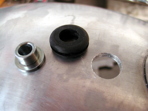
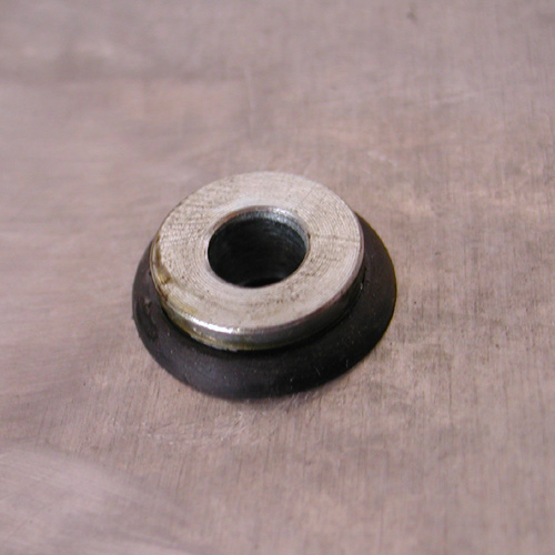
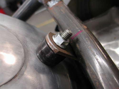
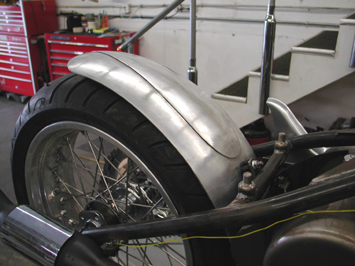
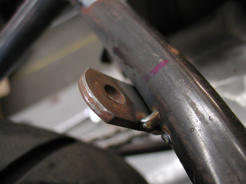
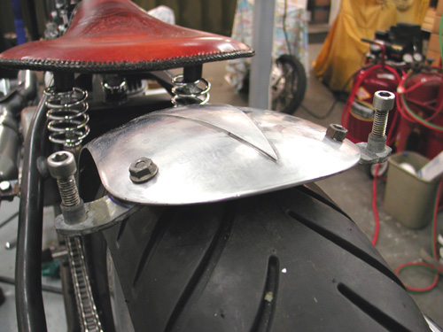
Here’s where it got tricky. I’ve been bending metal with a torch for years. Never improved my technique. Just the other day, a month after I built this fender rail system, I bought a small strap or tube-bending tool. Wish I had it when I went after this project.

First I built the fender strap out of a piece of exhaust pipe bracket. It came with two 3/8-inch coarse tapped inserts in each end. My plan was to build a fender rail system with tubing so I could adapt a couple of running lights on the tips. I carefully bent and drilled the strap and fender.
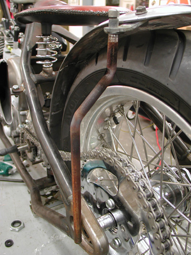
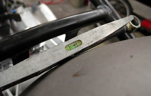
Then I bent the tubing fender rails to fit over the chain and tacked tab to the Paughco frame. One item I often attempt to use is a level. I’ll level the frame from side to side, then strive to keep all the other elements level. It helps.
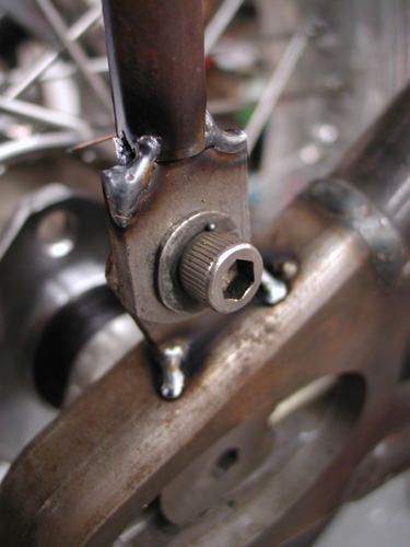
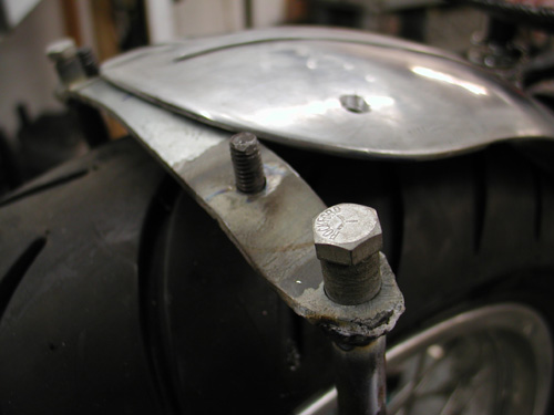
Here’s a perfect example. As I finished my welding chores, I got on a roll. I thought– wouldn’t it be cool to weld the fender bolts in place from the bottom. They would never come loose. Note the angle. There was no way they would ever return through their mounting locations. I was forced to grind them off and clean the holes.
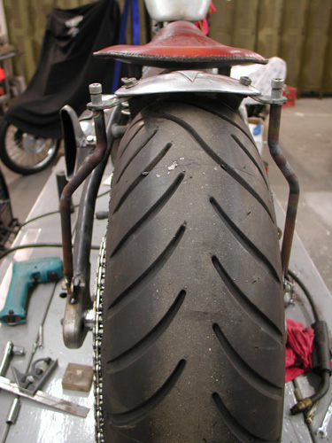
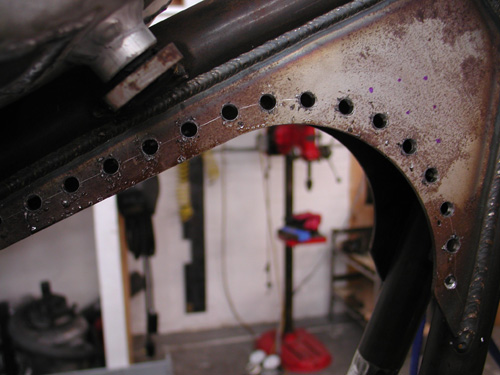
Here’s the finished fender rail system. I drilled holes in the frame and the rails to run wires. I still haven’t found the perfect running light style that rocks my boat and will afford me enough room to use the proper fasteners. Hang on!

Sturgis Shovel Part 9
By Robin Technologies |

This is strange. I’m writing several Sturgis Chop Techs after I returned from Sturgis. I’ll try to remedy that in the future, but we were so damn busy trying to complete the bike and run Bikernet, we didn’t keep up on the techs. Many apologies.
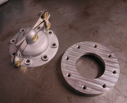
This piece covers the installation of the hot Speedster cap from Crime Scene Choppers in the modified stock XR 750 factory tank. Later, you’ll discover, that this highly modified, strengthened and extra rubber mounted beast was my Sturgis nemesis. But more on that later.
We added rubber-mounted bungs to the back of the tank. I moved the petcock to the rear and filled the center for a 2.76-gallon gas capacity before it hit reserve. I doubt that it contained more than a quarter tank of reserve, so I’ll toss it a 3-gallon total gas capacity.

Oh, I need to thank Cyril Huze, who designs beautiful steel tanks for the opportunity to experience an aluminum tank once more. He suggested this classic for the Sturgis effort.
I’m not holding it against Cyril. He’s a master and I’m the bungler for attempting aluminum on a 93-inch rigid S&S hot rod. As you’ll see the vibration aspects came from several sources that I could have remedied. It’s all just a roll of the dice.
When I received the Speedster cap I drug the cap and tank down the street, about three doors, to Bill Hall’s Welding. He handles my aluminum welding, since I don’t have a TIG welding system. I’ve got the rest, but not TIG. I would highly suggest a TIG system for quality welding capacity and good looking welds. It’s much like welding with a torch, so you’re certain of the bead and depth of penetration.
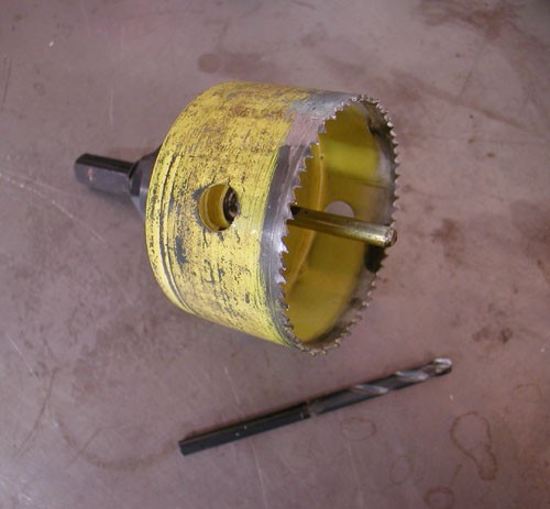
Bill’s a retired designer who enjoys welding and fuckin’ with his customers. “How are you going to drill the hole for the bung,” he asked?
I was thinking about die-grinders and files. I knew it would make a mess. Bill hooked me up with a 3-inch hole saw. He suggested that we hit a marine store for a tapered dowel pin (used for plugging holes in the leaking hulls).
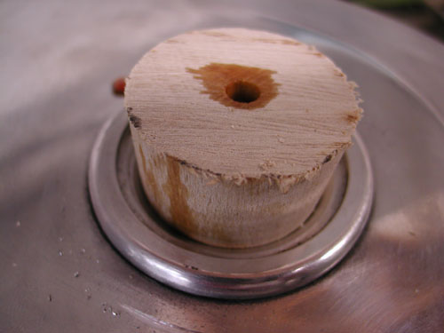
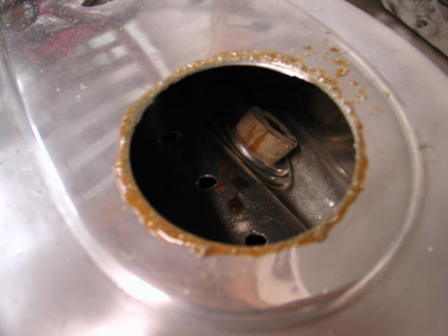
The key was to drill a perfectly centered ¼-inch hole to maintain a center approach to the cap bunghole. I drilled it and then ran the tapered wood dowel into the tank.
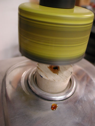
Then we set the tank on a pad on the drill press platform and lined up the hole saw. I used plenty of cutting oil on the edge of the blade and aluminum face to prevent the tank from snagging or catching. I knew how tender the surface of the tank was. We oiled the hole in the tapered wooden plug and carefully went to work. Bill’s formula worked like a charm.
Next, we needed a tool to hold the Crime Scene Speedster bung in place. I grabbed a piece of strap, drilled a hole or two and mounted it with the supplied hardware, which was brass. You can order the cap with several styles of fasteners for your application.
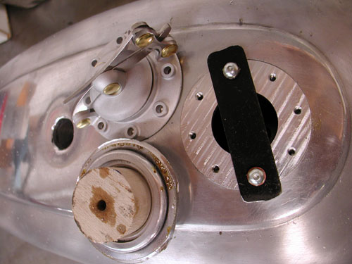
It was off to Bill’s for welding. While the gaping 3-inch hole was available I could have made a tapping tool and tapped out any imperfections in the tank walls. I dinged it way back in the beginning and never got around to fixing it. I left her be, as if it was the first injury and she needed to stay. I know it’s one of those wild superstitions.
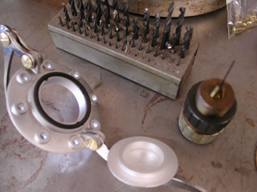
Okay, so during the “read the directions” phase, I noticed the bit about a non-vented tank. I would need to drill a tiny, cunt-hair hole in the cap of the tank. I discovered that I actually had such a tiny fuckin’ drill and dug it out. I had to find a chuck that pinched down to that size. Then I had a wise ass notion to drill the initial hole about 1/8 inch in diameter, since drilling with hair-thin bits causes easy drill bit breaks. The thinner the surface the better.
So, I initially drilled the inside of the cap with a 1/8-inch drill and drilled right through—Bummer. Ultimately I tapped the cap with a 10-32 then drilled the stainless Allen stud with the tiny drill bit. Then I screwed the stud into place and the job was finished.
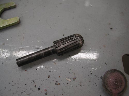
After Bill welded the bung into place it was my job to grind the welds down and ship the tank to Foremost Powder for a clear coat. I hit the big spots with a grinding tool. I tried my damnest to take only meat off the welds and not off the surrounding tanks surface.
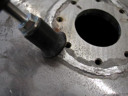
Next I used small emery discs to carve at the aluminum bead. I also smoothed some of the welds on the front of the tank where we filled the tunnel for additional gas capacity.

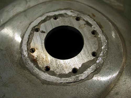
This shows the different grinding phases to reach a level that’s still strong with weld bead but handsome enough to live with. This was an interesting effort, since no bondo or thick urethane would be applied, covering a myriad of mistakes. This was the final stage before clear powder from Foremost in Gardenia, California.
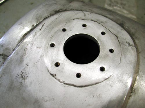
After this stage I polished the panels of the tank and hauled it off to the powder masters. There’s one other process I need to explain. I made every effort to clean the tank of debris and shavings. I also made sure to run a gas filter. I still had problems, which I will explain in my Sturgis Saga. They were easily remedied through Lee Chaffin at Mikuni. Just needed to dial the right number.
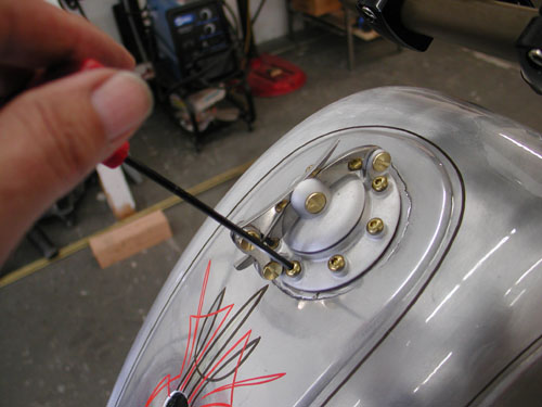
This shot was taken after powder and pin striping when I installed the gasket, decided which direction I wanted the cap to face and screwed the brass fasteners down. The cap worked flawlessly all the way to the Black Hills.

Sturgis Shovel Part 1
By Robin Technologies |

We're starting another project at Bikernet, the Ultimate Chopper. I dediced that title was bullshit. I look at some of the bikes built nowaday and mine pale by comparison, so screw it. It's the Bandit/Sturgis 2005 Chop. It's been a couple of years since I built a bike for myself. Hell, I can't ride the shrunken FXR, it's too small. Besides I need a rigid chopper for everyday flying. I gotta tell ya, I love choppers, like women. They're sleek, slim and move with an indescribable grace.
Here's the design notion. No we're not trying to compete with the Martin Brothers, Paul Yaffee or Matt Hotch, who are all master craftsmen and artisans in the custom motorcycle world. They are incredible and I have the utmost respect for each one of them. I'm sorta Indian Larry West. I want to build a light agile chopper for the ride. I'll attempt to explain. I've been riding choppers most of my life. I've tried out many styles, but consistently come back to the mighty light weight chopper.

Let's get specific. I needed something stretched to fit my 6-foot, 5-inch frame so were going with a stretched Paughco Rigid with 4 inches in the downtubes and 3 in the backbone. But I'm sticking with a very moderate rake of 35 degrees for handling. I'm running a 9-over light tapered leg Paughco springer for class and city handling. I'll run my traditional Custom Cycle Engineering risers for limited handlebar vibration and traditional appearance.
One of the notions is to make this bike a very reliable, rideable chopper for long hauls, maybe to Sturgis next year. I would generally run a 96-inch Evo to fit the rule, but this time a brother, Richard Kransler cut me a deal on a Shovelhead engine with 3 5/8 bore and 5-inch stroke. That over 100-inch monster would tear this bike apart in short order so I called S&S for advice.
We're going to roll with a tried and true S&S formula for street power, reliability and balance–same bore with 4.5-inch stroke will give me 93 inches of grunt. I tore the engine down for modifications last week and shipped the lower end to Viola, Wisconsin for a S&S blessing.
In keeping with the chopper code of the west, no fat assed tire will cramp the handling. I'm going with only an Avon 180/18 and a 21 on the front. No wild billet wheels but clean Custom Chrome polished aluminum rims and 40 stainless steel spokes. This bike will have a touch of chrome, but not much. I'm going to start a bin of Stainless Allen fasteners to take care of assembly.

I'm not going to run anything that sticks out from this bike, no sidemounted license plate bracket or wide bars, just tall risers and what I call TT bars that I will narrow for splitting lanes on LA freeways.

I may use a flush mount Sporty tank, or perhaps a Cyril Huze job like the one on the Shrunken FXR. What a sharp tank. I'll use a BDL belt, Compu-Fire alternator/ regulator and single fire ignition for reliability. We're mounting Kraft Tech fenders and oil tank, making our own pipes and brackets. Dewey's custom pegs will be used because they're light and contain just enough rubber to keep vibration away from feet and hands. The foot and hand controls are all Joker Machine for true reliability and simple clean design.

The Jim's 6-speed overdrive tranny is waiting a Custom Chrome Sprocket and Rev Tech O-ring chain. Finally I'll research the best possible sprung seat for comfortable, vibration free ride.
We're shooting for a bike that will be solid for the long run. It'll run strong, won't vibrate to shit, be reliable enough to ride to Sturgis, a street fighter in the old school fashion. Not a lot of flash, but tremendous class. Watch as it comes together right hear on Bikernet. Oh, I've got a couple of tricks up my sleeve that will be revealed as we turn this pile of parts into a running gargoyle.


1928 Shovelhead Project Part IV
By Robin Technologies |

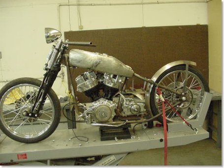
One of the best aspects of building bikes nowadays is the integrity of the components. If you get the right mixture of components together and take care with the wiring and assembly, you’ll have a bike as reliable as factory stock. That’s one of the reasons Bandit has moved to using Compu-Fire electrical components on most of his bikes. First, because even he can install them, and most of all, because Compu-Fire has been building electrical components for years. The stuff doesn’t break.
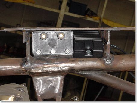
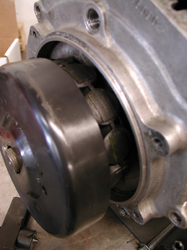
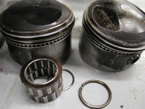
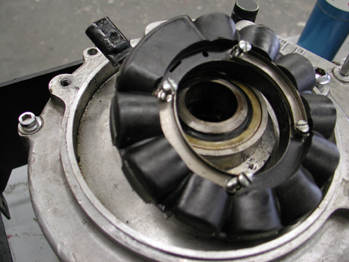
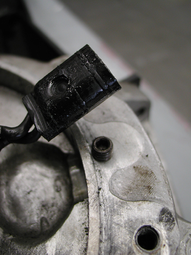
Take, for instance, this charging system. The stator slips firmly in place over the engine sprocket shaft race area and Compu-Fire suggests that you use the stock fasteners with a drop of red Loctite to ensure it won’t ever come loose. Compu-Fire alternator plugs are the protruding variety from the late-model design. Carefully oil the plug and slip it into place, then replace the plastic bridge and fasten it with blue Loctite. If you have new cases, make sure there are no sharp edges on the plug opening. File if necessary. Then with the shaft seal .090 shim in place, use a wire feeler gauge to determine that you have at least .060 of clearance between the rotor and the case.
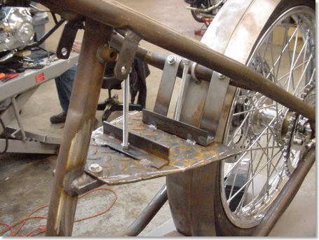
With each Compu-Fire charging kit for Shovelheads or Evolutions comes a thrust washer that goes on the outside of the rotor on chain primary systems. It may not be necessary on belt drive primaries. Mr. Gillihand from Compu-Fire recommends that you have a direct ground to the engine cases. Compu-Fire charging systems are the series type, unlike the shunt variety. The difference is that a shunt type drives the charge to ground if the battery is satisfied, causing the alternator to heat up and constantly work. The series type shuts the stator off when the battery is satisfied, which allows the unit to cool. The hot wire goes directly to the battery through a circuit breaker, or to your ignition switch on the hot side. In this case, the regulator was positioned with the coil between the tanks so the plug wire had to be extended.
That covers the basics of installation. Now here are the specs: Compu-Fire manufactures two versions of its charging kit, a 32 and 40 amp. From 1970-’75, stock charging systems were rated to 15 amps; from 1976-’80, they were 17.8 amps; between 1981 and 1988, they jumped to 22 amps; and finally, in 1989, skyrocketed to 32 amps. Now fuel injected models run 38-amp systems. So the two systems cover the lot.

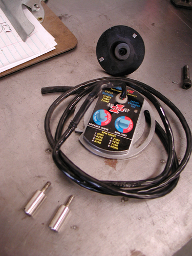
We’ll get into wiring after paint and chrome. The ignition system is Power Arc. The timing module is in the nose cone and the coil is also positioned under the seat with a chunk of angle iron. This system is about as clean as you can find.
Next week we’ll hit the final sheet metal as we close in on paint and chrome, and the lovely Princess Lena, daughter of the rich and powerful Rick Fairless, king of the Strokers Ice House plantation, makes her move on the hapless Bandit. –Wrench
1928 Shovelhead Project Part II
By Robin Technologies |

In a dank dark corner of a dusty debris strewn shop behind the Strokers Saloon on Harry Hines Blvd in Dallas was a small stack of bike parts guarded by a massive starving pitbull with one eye and most of one ear chewed away. The beast was so vicious that it once chewed through a 1/2 inch tether cable, and ate four Avon tyres before it could be subdued and chained in place. No one had the balls to feed the animal and it ran off so many customers that a collective decision was made to relegated the dog to guarding our Shovelhead project. It was like a death sentence. The lovely Lena, the 14-year-old daughter of Rick and Tina Fairless, the owners, who was scheduled to be Bandit’s 6th wife had a fiery temper and told Bandit, in no uncertain terms that the bike would be completed until he left the other women behind and came to Texas to settle down. The Dallas crew surmised that it would never happen so the fuckin’ dog would starve to death waiting for Bandit to return to collect the fair Lena and complete his pact with the marriage counselor.
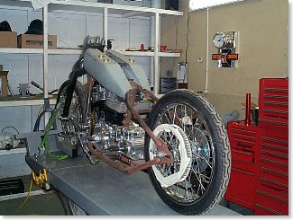
Unexpectedly during a freak Texas panhandle thunderstorm Bandit walked into the shop, carrying a turtle the size of a baby moon into and asked for the Lovely Lena. Upon presenting her with the turtle, her hardened resolve melted like a torch to a metal hanger and she swooned then demanded that her crew set to work on the project. We apologize for the long-winded explanation, but it’s important to understand all the delicate facets of this project to obtain a feel for the treacherous nature of this undertaking and the lives that hang in the balance.
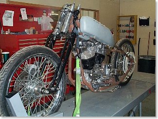
Just then the mega Dallas Easyriders store had a mass exodus of mechanics. Two were hospitalized trying to reach the parts, one died. Several were so pissed off at the shear audacity of Lena’s order that they started a competing business down the street. In reality they were so jealous of Lena’s affections for Bandit that they could no longer work and watch her dance through the shop on air. Enter Jim the transplanted fabricator from Florida who was hired before he knew what he was getting into. If you’re not from Texas, you won’t be familiar with the labor laws. Chain gangs are not exclusive to the Texas Penal system. They are a common phenomena in the work place. Jim hasn’t seen his family since going to work for the Fairless contingent. Between you and us, we have slipped Jim a note that once the project is finished we will spring him in the crate they plan to ship the bike, but that’s another story.
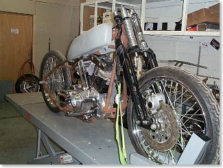
Jim has now modified the tanks for fit the Paughco rigid frame, mounted the engine and trans and front end. Randy Simpson is bending the bars for the project. Jim his building a box for under the seat for the battery since the oil will run from part of the gas tanks to the engine. If you note the belt pulley, we are now planning to run a chain for authenticity and since some other aspect of the bike forced us to go with a chain. We are still looking for the ultimate taillight to go with the project, and we hope to lower the front end enough to make the tanks more level, with Custom Cycle Engineering lower rockers. The front wheel is the stock Bad Boy 21 with an Avon tire. The rear will also be an 21-inch Avon with disc brakes. Pipes are scheduled to be reproduction stock early shovel pipes from Paughco.
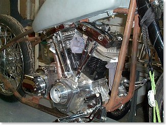
Watch as this project comes together. All bets are that the San Pedro Police bike with never even see the border of California, unless she sees the coast before the bike arrives. Stay tuned.
–Wrench
Sturgis Shovel Part 2
By Robin Technologies |
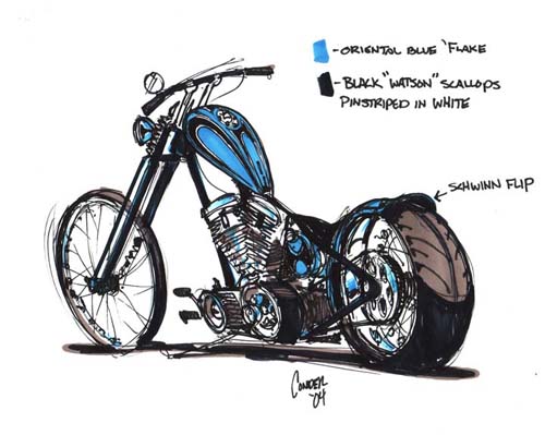

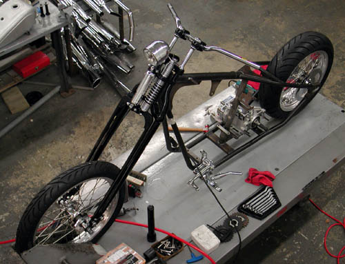

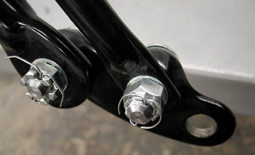
This bike might look like shit, but it should work perfectly. I'm endeavoring to keep it light, tight, narrow and right. So far so good. We've even decided to eliminate paint from the equation, except for rusty metal that may need black powder coating from Custom Powder Coating in Dallas, and the front end was powder coated black at the Paughco factory.

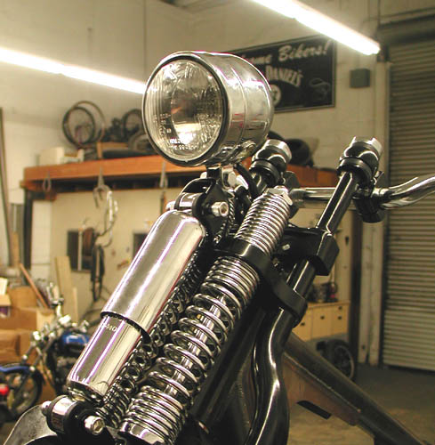
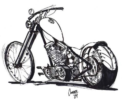
Let's jump into the shop. I was jazzed to receive my Rev Tech wheel order from Custom Chrome. I needed to mock up the frame and ship an image to Tim Conder for a concept drawing. Conder's images inspire any builder. I couldn't move on it until the Custom Chrome wheels were delivered and mated to the Avon Venom tyres. I'm also going to avoid chrome and flashy stuff as much as possible. We're running bare metal in several instances: Wheel rims, aluminum tank, brass fender rails and linkage, copper hard oil lines, and thick wall copper tubing bars. Dig this, we're going to galvanize the frame, rear fender and oil bag. The XR Sportster racing tank which is aluminum was delivered from Cyril Huze. I'm going to leave it brushed aluminum, but the capacity was a minimum 1.75 gallons. I'm mounting it high on the frame so we'll open the tunnel for additional fuel capacity and weld the area shut.
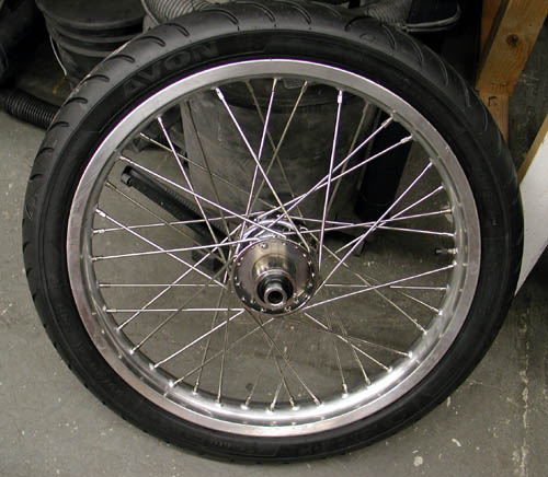
I'm jumping around. Let's get back to the Rev Tech wheels. The spokes are stainless with polished aluminum rims for a long lasting approach. Even the Paughco frame came with brushed aluminum axle plates. We're going to leave 'em alone. Cyril Huze designed a new, between the heads, coil and ignition switch mount. I ordered one without polish or chrome. It's unfortunate that we can't get wheels with Stainless hubs and eliminate chrome all together. The front is a 21 with a 18 by 5-inch rear for a 180 Avon Venom. I don't want a super wide tire. I'm specifically avoiding wide tires. I think they make choppers look like fat-assed chicks. They lose their chopper code of agility and lightness.
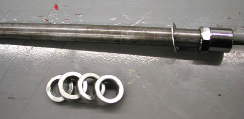
With my Doherty wheel spacer kit I was able to set up wheel spacing quick, for the time being. It's a trick working in the shop by myself and I will try to explain some operations from that perspective. We all face shop blues from time to time. Makes me kick back and rethink various operations when six hands are needed and I'm limited to one on the part and one on the arm of the drill press.
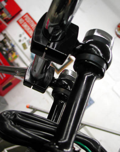
So alone one night I grappled with the installation of the CCI neck bearings (I need a JIMS tool for the races), to install the Paughco springer front end. After a trip to a local fastener store I was able to weave two studs into the rear legs of the front end for traditional, vibration dampening Custom Cycle Engineering risers. The studs needed were 1/2 inch about 2.5 inches long with 1/2-20 threads on one end and 1/2-13 on the riser end. The shop only had two different-length studs and one needed additional tapping to fit.
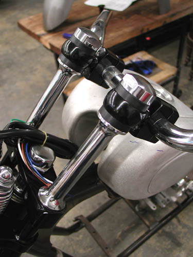

I use these risers on most of my bikes because of the traditional, old school appearance and the vibration element for long runs, but they take a degree of thinking since they shove the bars toward the rider (and often the tank) about 2 inches. I needed to watch for the appropriate amount of tank clearance and ultimately needed the 1-inch longer stems. Very high bars can be a problem with the leverage against the flexible rubber, but with patience, they will work fine. Since each riser is a single unit, they will flex and pivot until they're aligned and tightened down.
I installed low rise drag bars from Custom Chrome/Khrome Works. I'll see how they fit as the seat is mounted. I ordered a seat at a swapmeet this weekend, black with brass buttons by West Eagle. My plan is to bend thick-walled copper tubing and polish it for the final bars.
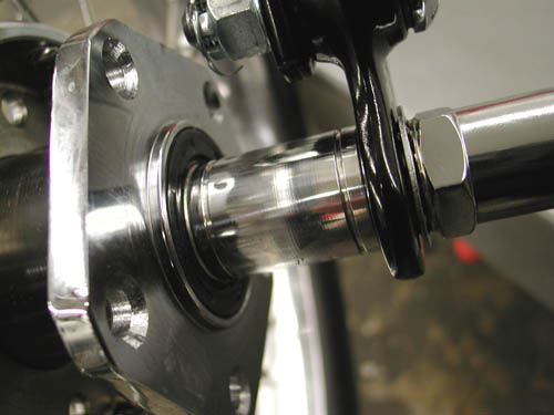

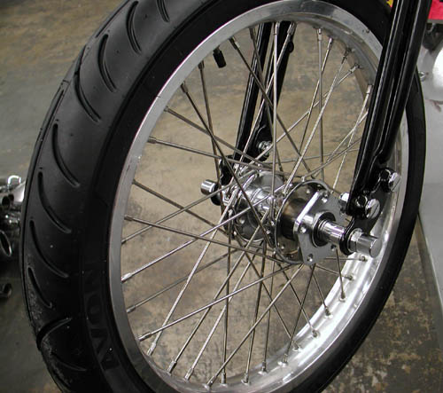
Now Imagine the first time I installed the front wheel, wrestling with the slipping front end and frame, the front wheel, the axle and the spacers simultaneously. Fortunately my 11-year-old grandson was on hand with a rubber mallet to assist. For the rear I used a crate to hold the wheel and the approximate height so I could muscle the axle and spacers through to align it with the frame. It was time for a Corona.

The engine is currently in the hands of S&S for a breast reduction from 103-inch to 93 smooth inches of reliable horse power. I'm waiting on the engine build images to share with you.
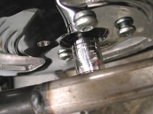
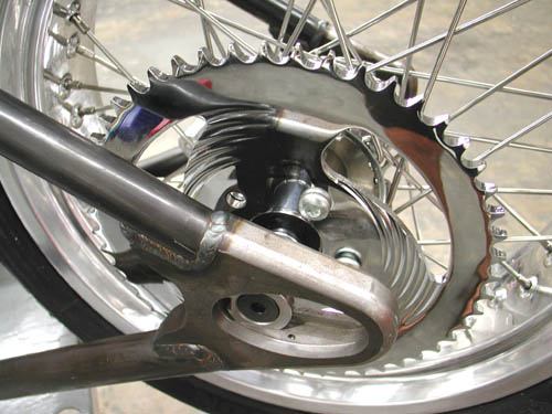
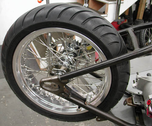
Hold on, I'm slipping the clutch again. Next I mounted the Rev Tech rear wheel with another Avon Venom within the Paughco frame. Unfortunately my Kraft Tech Fender is 9-inches wide and the tire on the 5-inch wide rim runs only 7-inches. I need about an 8-inch wide fender. I'm waiting for the shipment to arrive.
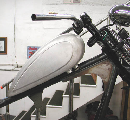
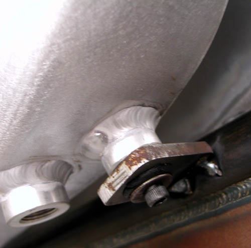
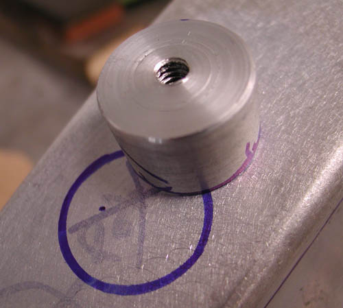
Then I moved onto the tank. I needed to create a couple of bungs for rubber mounting the rear of the tank and tap them for 1/4-20 threads. It was the first time I used our new/old lathe. This is all a new learning experience at the new Bikernet Headquarters. I grabbed a lathe that was rusting in Japanese Jay's backyard. He wasn't using it and I wanted one to cut wheel spacers. I reworked and cleaned the lathe until it was operational then the Doherty crew created a wheel spacer kit? Ah, but the lathe has a myriad of uses, like cutting bungs from a chunk of aluminum. Worked great.
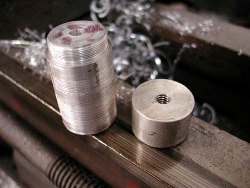
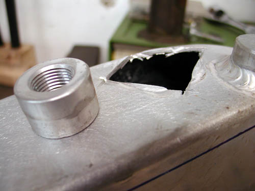
Then I tapped them using the lathe chuck. I discovered that the tank petcock bung needed moving to the rear, since the tank was mounted at an angle. I cut it out with a die grinder and returned to the lathe to machine off the welds.
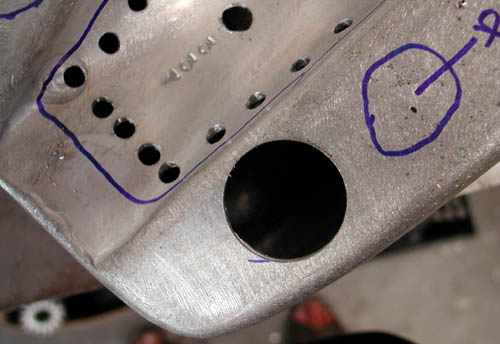
Next I need to learn how to use my new/real old, milling machine. My dad was a machinist most of his life and ultimately an engineer in the oil well industry. As a teenager I worked in machine shops and picked up equipment experience between smoking joints. I swear I learned something.
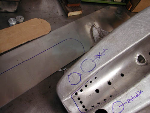
Let's see, what else. I dug through our parts bins and found the exact bracket I needed to mount the Kraft Tech oil bag. I need to cut off the existing coil and oil bag brackets and make a new front mount.
Wait a minute I'm slipping again. I dug through my bracket drawers and pulled a couple of old Jammer brackets 1/4-inch thick. I drilled 1/2-inch holes for the rubber mount grommets from Cyril Huze. I bolted them in place.
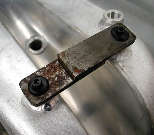
Next, I carefully measured the backbone tubing of the frame and figured the dimensions of the tabs and carefully marked and cut them, then beveled the edges for strong welds.
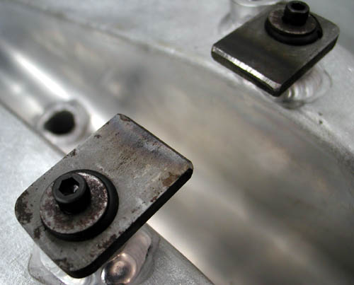
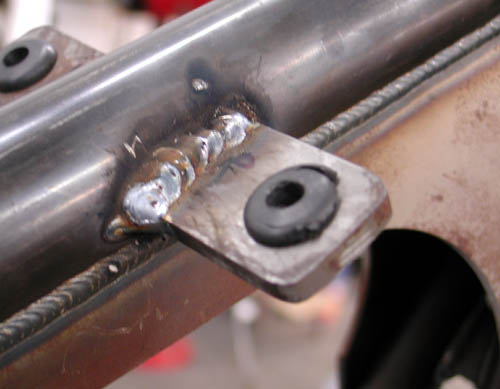
The next day under a sober sky, I refit the tank, tacked and MIG welded the tabs. Once the Bill Hall, pro-welder, welds my tank bungs in place and the tunnel is capped, I can make the final rear tabs and mount the tank semi-permanently. Is that possible?
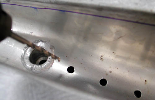
Next, I will mount the Kraft Tech Oil bag, the rear fender and sprung seat mechanism. I'm also dealing with the rear drive. The frame was set up for belt, but more and more I like the chain notion.
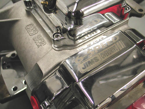
The JIMS machine tranny is set up for 4-speed applications with 6-speed gears. First, I ordered the wrong Custom Chrome tranny plate, then I was twisted about the sprocket vs. belt pulley needed to drive the bastard. I dug through old parts bins until I found gears, since it looked like a gear-driven job. Then the sprocket didn't fit. I'm still trying to figure it out.
I'm going to meet with Jim of JIMS in the next couple of days and get to the bottom of it.
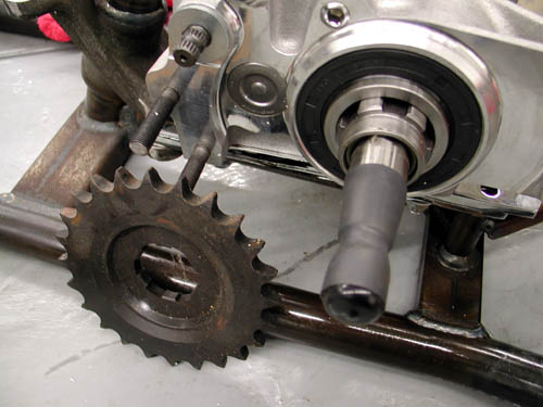
Although the frame is set up for a belt, that means if I run a chain, I'll have plenty of alignment flexibility. Hang on for my next report.
–Bandit
Doherty Machine
1030 Sandretto Dr Unit L
Prescott, AZ 86305
928-541-7744
mailto:Dohertymachine@aol.com
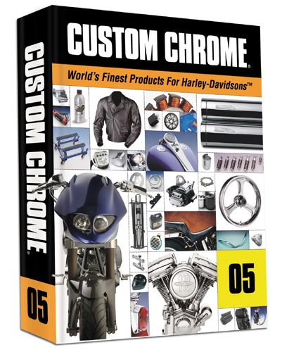
BRAND NEW CUSTOM CHROME CATALOG RELEASED–
Want the Custom Chrome's new offering for 2005. The California based distributor brings you the most comprehensive product offering in the Harley-Davidson aftermarket! At over 1,500 pages and over 25,000 part numbers, their 2005 Catalog features the new RevTech 110 Motor, Hard Core II, bikekits, frames and forks–everything from nuts & bolts to performance products. It's the Custom Bike Bible for the year. No, this is not the latest book, just click on it to find the real deal.
ONLY $9.95 + 6.95 Shipping**
** Price may have changed.
1928 Shovelhead Project Part 1
By Robin Technologies |

In an effort to stay tuned with the rapidly growing and ever changing industry the staff of Bikernet began a project Shovelhead several years ago in conjunction with Randy Simpson of Milwaukee Iron and Arlen Ness. It’s been a strange road, but we’re now rolling closer to completion with the assistance of Rick Fairless of Dallas Easyriders and his ace fabricator Jim.

The project began with the purchase of a slightly destroyed Mexican Police bike from Arlen a couple of years ago. He had scored some 300 1984 Mexican cop bikes that had been ridden through several revolutions and costly rebellions. The bikes were shot at, dragged, bombed and ridden harder than any V-twins on the planet. When we first purchased the Shovel complete with police sirens and blinkers, we assumed foolishly that we would restore it to it’s original fighting condition. Arlen even hand picked our unit specifically with our goal in mind.
Well it’s one thing to dream of a restoration, but when the cast iron triple trees are broken, the frame is bent, all the sheet metal destroyed we took a step back and said, Help! We pulled the Engine and sent it to JIMS Machine for a rebuild along with the Transmission. With the cases replaced along with the barrels and heads and all the internals replaced, the engine was ready to rock once more. A similar concoction was mixed for the transmission and a couple of us dressed all in black and prepared to bury the chassis in a shallow grave in the desert outside of 29 Palms, California when the Editor of “Biker” pointed out that we had a valid pink slip. Dean, salivating, over the dying chassis took the entire unit and paid us handsomely for the paperwork. We suspect that he made a rocking chair out of the frame and wheels. During one of our weekly Bikernet meetings we discussed what to do with the Shovelhead drive train, and in the process we started discussing various options and some of the customs we respected the most. Several suggestions were thrust onto the rusting boardroom table. First Randy Simpson had volunteered to help us build an old time looking bike from the remnants of the ’84. We voted unanimously to pursue this avenue, since we had always been impressed with the workmanship and design Randy injected into his own 1928 Shovelhead projects, and he had a desire to create a simple chassis kit to build one of these puppies to market to the public. We agreed to help him promote the concept. We also all agreed that a gesture to the community of San Pedro was a necessity since several members of the staff had been arrested and the headquarters were constantly under surveillance, so we decided that Bikernet needed its own private San Pedro Police bike. How else could we crash the local parades. Randy is a persnickety builder who takes great pains to build quality parts for the market. Two years passed and he still didn’t have the frame built. He was obviously so successful with his growing line of fenders that his chassis concept was slipping onto the back burner. Arlen Ness was also taking giant strides to build a similar machine and if you picked up a recent Easyriders you would have seen the fruits of his labor in his 50/50 Shovelhead. In addition Chrome Specialties with the assistance of Chico in Southern California had recently completed a similar project around a Sportster (It’s called Trick and is featured on Bikernet right now). The competition was stiffening. Randy dropped out, and we moved ahead, and with some research we discovered that a number of reproduction parts are being built in Europe for early Harleys. Early like in 1915.
Devoted to successfully completing this project we picked up a rigid frame from Paughco. This is a standard scale Paughco Rigid for Shovelheads. From there our old part contact was Fred Lange in Santa Maria California. Fred informed us that a European group is remanufacturing 1915 springer front ends, flat track tanks, headlights, fenders and Fred was making appropriate sprung seats for these models. We were in business. We ordered the flat track tanks, the fender for a side car so it could be used for the front and the rear, a hand leathered seat and snuck out of the hills over looking Santa Barbara.
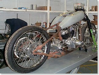
We had a Bad Boy front end, Wheels, etc. We’re in the market for some Custom Cycle Engineering lowering rockers. At that point we needed miscellaneous parts, pipes, etc., and we could get this puppy on the road. It was time to call in a favor. Rick Fairless had purchased the exclusive Bandit I Pat Kennedy Built bike from Bandit and part of the deal was parts and labor on a bike project in the future. It was time to call in that note. Then in a stroke of bad luck and good, Marty Ruthman decided to close his shop abruptly due to health problems and he had a massive sale.
–Wrench
Mudflap Girl Part 1, the Concept
By Robin Technologies |

Life is nuts, or is it just me? Fortunately, we have motorcycles and women to chase. And this year became the year of the Evo, the FXR, and the mudflap girl. I’m scratching the back of my head and wondering how to kick off this build for 2011. There’s a lot on the plate this year and it’s a tad difficult to explain. First, I must fess up. I’m turning 63 this year and no more riding rigids to Sturgis, or even chasing young broads. Ah, but the adventure continues. It’s actually a blessing not to be hassled with women troubles. I’ll let my son, who just turned 37, deal with the addiction to soft curves. I’ll hide out and watch…


The solution for my missing long distance rider was an FXR, and I have one, the John Reed V-Bike that I took to Bonneville in 2006 and set a 141-mph record with a top speed over 150. Unfortunately, I have a hip problem and can’t ride mid-control bikes anymore. I even modified that puppy, but that didn’t do the trick. I love that bike. So, what the fuck was I going to do?


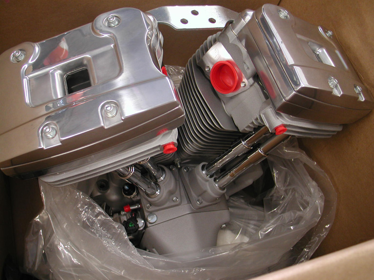
Okay, so I started to piece this bike together. We factory re-manufactured a ’98 Evo engine and JIMS rebuilt the transmission into a six-speed. I had a couple of Renegade Wheels and Progressive Suspension shocks. Then I had a conversation with Kenny Boyce, the man who designed the Pro-street FXR frame. He wasn’t happy with now-defunct Quantum. I also found out that some of these frames break in front of the seat area at the backbone. The project was moving forward with a Custom Chrome, super-wide, upside down front end, Aeromach risers, and we added super wide, Burly bar highbars.
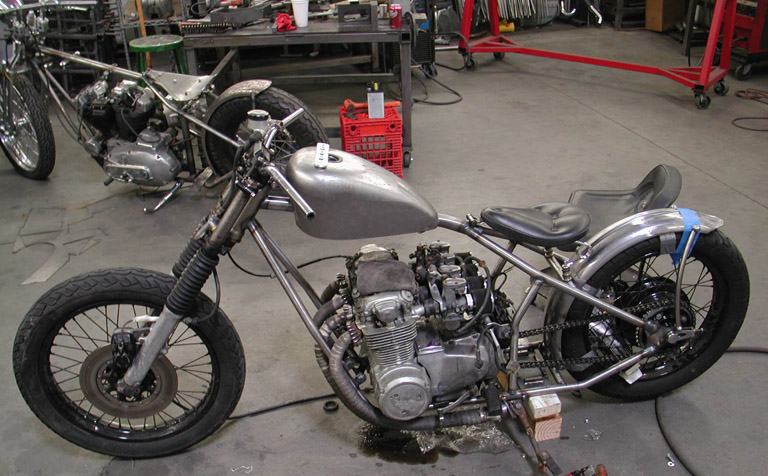
I even had an aluminum mudflap girl oil tank I ordered from Nick at New York Choppers. The bike was leaning toward a pro street touring model with a set of Redneck Softail fiberglass saddlebags and a Klockwerks touring bike rear fender.

I was rolling when Kim Hottinger called and asked if I could haul my old ass out to the American Built/Spitfire manufacturing facility in Rancho Cucamonga, California. Paul Cavallo was the engineer/manufacturing guru behind Hellbound steel. As we watched the production chopper industry dry up, in the wake of a floundering economy, only the diehard survived, and I wanted to support anyone who understood the code of the west.

The brothers who love motorcycles, choppers, bobbers, and custom parts continued to jump up every morning and do what they adore, work on motorcycles. Some went from building hundreds of bikes every month to a handful, but they kept building. Paul downsized and kept rolling with his father at his side. When I saw what he was up to, I was inspired. He can build any frame, for any motorcycle configuration, so my mind went wild. We could build a Frisco’d and stretched, single-loop FXR, and I dragged an old Durfee girder out to his facility so Paul could see how the master built the originals. Imagine an FXR with a state-of-the-art girder.

Paul is a wild man when it comes to building and manufacturing anything. He re-engineered the girder and refined the looks, and added two shock mounts to incorporate a state-of-the-art front suspension. Over the next year, you’re going to witness Paul’s Spitfire abilities with features in several national magazines, and you’ll begin to see his products pop up in Custom Chrome catalogs.


The more we moved forward with this bike, the more inspired I became. This was a bike for me, maybe the bike for my old-guy riding future, now that my Road King was down the road. So I went to Paul with the deal of the century: build two of these frames and front ends. I spoke to Paul, then to my son.

There had to be a goal behind this effort. We would ride to Sturgis together. Shit started to happen fast and I ran into a TV producer who wanted to follow the build, and Leomark studios got involved.

Next, I reached out to Chris Kallas and we started to work up a concept drawing. Here’s some of the e-mail that flew back and forth.

Here’s my initial description:
Frank’s bike: classic black mag wheels from Metalsport. Klock Werks rear dresser fender on Frank’s, might bob it. Both wheels will be mild width. Mudflap girl theme on my bike and Hardball tattoo on Frank’s. Paint reversed from Frank’s bike to mine. Forward controls on my ride, Frank’s will run mid controls. Rubber pegs, grips. dog bone-style tall rubber mount risers. Shotgun pipes. One Redneck bag on the left of Frank’s bike. We also talked about a small front fender.
–Bandit

Some questions?
Black and chrome or silver Evo engine?
Your wheels? Mag or spokes, what kind?
Style/brand of headlight, tail light?
The risers are the type with rubber mount at top?
Carb/aircleaner?
Shot gun pipes, staight, no mufflers?
Style of seat?
Your fender the same not bobbed?
Brakes? Dual or single up front? What brand of rotor/caliper?
If any of these things aren’t specific yet, they could be semi generic on art.

If you can send any photos or links to of fenders, wheels, bags, brakes or controls, it would be helpful.

As for paint, just a thought.
It looks good with lots of black or aluminum, and chrome.
It also looks good with your signature orange accents or striping. Since I’m not crazy for white frames, they could both have blue frames and just flop the two-tone paint on the tanks and fenders.
— CK 
Here’s the basic FXR platform showing the frame modifications.
This is with a 3″ extended swing arm.
I need to go back and recheck some measurements but it will give you a
rough idea of the stretch up front.
Is this the type of exhaust setup you were thinking of?
When you said shotgun and 2-into-1, I wasn’t sure.
— Chris K.
I think we should go with this type of exhaust, if we plan to pack passengers. I’m going to ask Dar about that swingarm, but my tendency is to extend it about 1.5 inches, not 3. The stretch looks great. Let’s fuck with those fender rails, arch them, or make them disappear and bob the fender slightly. Plus I think we will need to lower the rear at least an inch, with shorter shocks.
–Bandit
Hey, here’s my first crack at putting it all together. Overall the stance looks good. Since it’s a rough draft without much decoration, I just threw a couple
of mud flap girls on it. I thought I’d try a traditional Sportster/FX headlight with it’s rubber- mounted bulb to stay with the theme of using rubber pegs, grips, and
rubber mounted-risers…. not to mention a rubber-mounted engine, plus I like them.
The frame tube behind the shocks creates a challenge for curved fender struts. I’ve included a couple of photos of some frames so you can check out that area, plus for general interest I tried mounting the tank higher (Frisco style) but thought this looked better.
You might use a semi-later model Sporty tank (when they first started making them larger but still had a carb).
I don’t know at what angle or how Spitfire plans to deal with the secondary neck brace under the tank, so just drew it how I thought it might go.

When you said a Fantasy in Iron tear drop air cleaner I took that to mean a plain Goodson (no rib), for engraving. (We now have a Roger Goldammer air cleaner for Frank’s bike)
Since you need to run a front fender, I made it small. I like when they show most of the top of the tire.

Questions:
Who’s handlebar and foot controls do you plan on using?
How about brake calipers?
–CK
Hey, Chris,
I feel like I want more attitude. How about the tank mounted in line with the bottom of the top bar and stretched a tad at the back to more of a point? Take out the stress bar and add a gusset there with a mudflap girl cut out.
Check the news. I ran a shot of the air cleaner, but you nailed it. Did you check out the heavy green flake and silver bike? I like that theme. My bike will have a plain engine. I thought that style worked well with the plain silver, driveline. And I liked the green springer to match the frame.

We don’t need to go with green. It could be almost anything and silver, then reversed for Franks, with a silver frame, and colored sheet metal.
–Bandit

If the Redneck bags wouldn’t fit, we looked at what Bob T. runs on his fantastic RT.
Part number for bags:
’87-90 FXRS conv bags
H-D 90702-89 left
90703-89

As you can see we are flying at this effort. Don’t miss the frame build in the next segment. As it turns out Frank and I will be running the same drivelines: JIMS six-speed transmissions and Harley-Davidson Evo engines.
Sources:
