Bikernet West – Amazing Progress
By Robin Technologies |


Late into the evening, Bandit, Nuut Boy, and my wonderfully-knowledgeable- self hammer, weld, bolt, space, and tear our beards out moving forward on Bandit’s rigid. The Weerd Bros front end is in place with the Roadwings 21-inch, 40-spoke wheel. The rear is a 180-18, both with Avon tires. The frame is stretched 6 inches up and 2 out. The trees on the clean front end are raked 6 degrees (photo 1). The S&S 98-inch stroker is bolted in place as is the 5-speed Sputhe trans.
We set the engine and tranny in place and then found a scrap inner primary to line everything up. With the stock 32-tooth pulley on the tranny, we put a 70-tooth narrow belt pulley from Harley on the back with a 134-tooth belt. It was too long. We tried to get a hold of the frame manufacturer for some guidance, but they wouldn’t get back to us, so we had to wing it. We had another option. Run a Harley Thunderstar 65-tooth wide pulley for taller gearing for the trip. We picked up a 130-tooth belt and it fit like a glove. The pulley on the wheel also felt good and afforded us plenty of tire clearance with the offset frame. With the rear wheel in the center of the adjustment axle slot and the tire centered in the frame, it was time to fit the rear fender. The rear fender was a Milwaukee Iron job, which took some time to mount up. First we centered the tire in the frame. Ignore the offset rear leg. Center it in the frame using the cross member behind the seat as a guide. We centered it then strapped chunks of 3/4-inch board (photo2) to the tire with green paint masking (low tack) tape.
Then we slipped the fender in place after the rear belt was adjusted. Again, make sure the fender is centered over the tire. The fender didn’t contour the tire completely, so you must decide what area you want contoured. We decided on the top, most visible area. Make sure the slot for the belt rides a good two inches above the belt and at least a 1/4-inch from the inside.
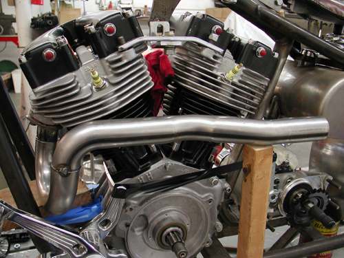
Then the Samson exhaust was removed from the box. They don’t build exhaust for rigids so natch the Dyna exhaust didn’t fit, since with rubbermount frames the engine sets higher in the chassis. They were also over 10 inches different in length. For performance we cut them to a more equal length (photo 4), about 27 inches.
We also ordered baffles and we cut them (guessing) to give the 2 1/4-inch exhaust some back pressure. Then we mounted them. The front pipe was way too close to the deck, so we cut 2 inches out of it and gas welded the pipe back together. During this process we were able to bring the pipe into closer alignment with the rear exhaust. None of the brackets would work so the madman with a torch went to work building brackets. The seat was also a trick. Bandit purchased an old cop solo with the plunger t-bar from 34th Station, a bike restoration shop on Pacific. After much contemplation he decided that he had to mount springs under the seat for something of a ride, but springs were a problem. He had some success with a set of valve springs on his dicey Knucklehead, “Made all the difference in the world,” Bandit said while pondering the ride. But the old Bates tapered 2- or 3-inch springs generally bottom out under any load. Then a bolt of lightening hit while attending the Harley-Davidson new model presentation to the motorcycling press. In addition to all the new models for 2001, they were showing off their new police bike, which had a sprung seat. Bandit drew the 4-inch crescent wrench he’s been carrying in his pocket for the last 32 years and began to take the springs off the new 2001 model. Seven factory executives struggled to pull him off the new demo bike. “But wait, guys. I just want to borrow ’em,” he screamed, pulling on his crescent wrench. Back at the top-secret massive 50-square-foot Bikernet testing facility, the gang was taking more measurements. It was determined that if he could narrow the seat one inch, all would fit, and the seat spring studs would line up with the center of the frame tubes. A call was made to California Harley-Davidson to order the springs, ASAP. Nuut Boy went to work stripping the seat to just the pan. With a die-grinder he cut a 1-inch strip out of the center of the pan then laid enough brazing rod into the jagged gap to sink a battleship. We decided not to use the old t-bar and with some standard 3/8-inch round stock, fashioned a triangle brace under the seat for support.
|
Bikernet West – Belt Drives Limited Open Belt Installation
By Robin Technologies |
 Here’s the deal. With less than two weeks to go I’m praying, laughin’, grinning and scrambling. The paint finally arrived from Harold Pontarelli of H-D Performance of Vacaville, California, and the dark haired beauty wanted to be at the shed when I opened it. I paced the floor waiting for her alabaster legs to bring her quiet self up the sagging stairs and into the world headquarters of bikernet.com. We took the carefully packed boxes to the basement where we were attacked by the foam peanuts assigned to protect the polished finish. First it was slabs of pressed foam, then thousands of bouncing peanuts, yards of plastic wrap, then plastic bags and bubble wrap until we finally reached the bright candy blue finish with cream flames, silver inserts, for dimension, and gray pinstriping. Unbelievable! The perfect match for the bike. I’m jazzed. But let’s explain some of the praying that’s going one. BDL Belt drives, especially this one in particular, are simple to install. Incredibly simple, but there’s a caveat, a loophole or a tiny chink in the armor. It’s called alignment and spacing. Hot Rod Bikes recently published a full-on BDL installation, and I read it several times. It never made any sense to my simple mind, yet it was full of very precise instructions. The key is how you install and space the motor and tranny. It turns out that your inner primary, or in our case, the motor plate, is the best alignment tool you have. According to Frank Kaisler, the editor, you leave the engine and tranny loose, bolt the inner primary or belt plate to the engine then pull the tranny into place and bolt it up tight and start checking under the engine and tranny for gaps with feeler gauges. In the article it showed big Frank filling the gaps with spacers as thin as .010. Damn, that’s getting touchy. Recently a Bikernet reader, Breeze, sent me the following on BDL installation suggestions and I added my two cents worth to his experience: “When I was installing the BDL 3-inch open kit (the one that comes with the motor plate) I was having a bitch of a time gettin’ the belt on. So, I called and got to talk to their tech support.”
“Anyway Buddy Bob, tech master, says, “Oooh, just file the pulley splines (Photo 1) it will go right on.” Filing splines applies to S&S motors with slightly larger main shafts, like .001 so take your time and it will work out fine. If you don’t and force the pulley on, you may have a serious problem taking it off. I used a handmade puller from the bottom of the tool box to get the pulley back off.” “As far as alignment I use the good ol’ straight edge across the pulleys method. Check at top, center, and bottom, to get things straight on both axis. I do this without the belt and space the front pulley out so you can use feeler gauges to compare the front to back space between the rear pulley and the straight edge. Of course the ultimate alignment test is to run it and see how the belt is tracking. It should not wander and should track on the front pulleys outer flange and center on the rear pulley.” “I think they have a great design there, it is one of the smoothes clutches I’ve run, but you need to check tolerances for reliable running. Be sure to follow the instructions on the clutch install, the Locktite they tell you to use on the basket splines is important for the basket to seat properly.” “They call me the Breeze, I keep rolling down the road!” Well, that’s the Breeze’s story. In fact Breeze has given me a couple more things to check. I put one of the polished rotor covers on, which threw my pulley alignment out of whack, so I had to take it back off. I’d rather have reliability that flash. Before you attempt to install the belt drive check these alignment areas. Bolt your rear motor mount bolts down tight, without the top one in place. With feeler gauges check the front motor mount. Space the front ones if there is any gap. Now bolt down the tranny plate and the tranny except for the single bolt on the right side (Photo 2.)
Check the clearance to the final stud from the frame and correct the spacing. Now with everything loosened up install the inner primary. The BDL system comes with a very heavy duty clutch bearing, so the the stock bearing race must be removed. Fortunately I had a JIMS puller for just that application.
That and a couple of crescent wrenches and the puppy was gone, and the new bearing installed. Slide the clutch and front pulley on, and make one more alignment check as you rotate the motor (Photo 4).
Grease the starter shaft and bolt in the starter pinion gear. Next install the clutch pack as per the manual. You can now install the belt guard and adjust the clutch. I’m carrying another set of clutch studs and springs, in case the clutch begins to slip. I’m hauling along another belt for safety, also. Couple of years ago, I ate one (it wasn’t a BDL, though). Seems like a lot of work, but actually this is one of the cleanest, simplest systems out there, and once you have it dialed in, you can put it on and take it off in minutes. Damn, I running out of time. Gotta git to the wiring. Rock and roll. –Bandit
|
Bikernet West – Electronics in a Weekend
By Robin Technologies |
|

Wiring is the nemesis of man, the puzzle of the best builders, the hornet’s nest of breakdown treachery. Bandit sat for hours drawing a wiring schematic for Agent Zebra’s Softail, only to rip it to shreds and toss it in the trash. He made lists while Sin Wu brewed strong coffee and baked peanut butter cookies. Bandit barked and growled for a couple of days with each run to the marine store for connectors, to the electronics store for switches, to the Custom Chrome catalog for components. The same formula fit his own West Coast entry in the Sturgis Bikernet Chop-Off. We knew as soon as he mentioned that the bike was ready to wire, that we should pack our shit and leave. We took the case of Jack fifths, the girls, and checked into the nearest fleabag motel. While we sat around the stanky pool and partied, Bandit thought about each wire, each connection, and each component. His mentor, Giggie from Compu-Fire, was his only sounding board and the only sonuvabitch big enough to snap back when Bandit growled about wire gauge or lost connectors. He wired the bike entirely with 14-guage wires. The only other sizes used were for the battery cables (stock units) and the wire that ran from the battery to the ignition switch (12-guage). Even when the sexually starved statuesque Asian roamed into the garage with cocktails, adorned in a sheer negligee, she was ordered back to the headquarters. Soon she found another plaything to keep her occupied, but that’s another story. Wiring, in the big guy’s mind, is a process of understanding what is happening with each component, where each component is located, watching for the safety of each wire, keeping the bike sanitary, and organizing each group of wires. Each wire is covered with shrink tubing, each connector supported with additional shrink tubing. Each bike had a minimum of wires carefully placed. Each bike had a minimum of components to keep the wiring process uncomplicated or enhance the reliability of the machine. No turn signals, no handlebar controls, and no micro switches. He used only millspec (military specifications) or marine quality switches. Vibration is a killer on motorcycles and much the same on boats, in addition to the moisture considerations. One additional component made wiring simple and risk free, the Custom Cycle Engineering starter mounted mechanical switch. (Check the article here in the Garage.) This unit eliminated the starter button, the starter relay, and all the associated wires. You must make sure you will have access to the switch, which is mounted directly on the starter, under the oil bag, (Photo 2) which can easily be interfered with by the position of the exhaust pipes.
 Photo 2
The concept is that you physically push the solenoid into contact with the starter gears and electrically engage the starter. We chose a Compu-Fire starter from Custom Chrome to kick this 98-inch monster to life. The key thing on fucking up starter motor installation is over tightening the brass lug wire fitting. It may turn the connection on the inside of the starter and ruin the contacts. Compu-Fire has designed a new line of starters which feature 6:1 gear reduction (Photo 3) and a 6-pole permanent magnet field to eliminate starter stall-out.
 Photo 3
These units deliver maximum cranking torque without overloading the battery. They also eliminate starting problems on fuel injected bikes. Only two switches were used and one 30-amp H-D (common at any electronic or auto parts store) circuit breaker. One on-off marine toggle for the ignition, which energized the Compu-Fire single-fire ignition system, the hydraulic brake switch, and the taillight. Since all the sweet parts like handlebar controls, foot controls, mirror, and taillight were Joker Machine components, he was in luck. Joker works the brake light switch into the body of forward controls, which eliminated the bulky hydraulic switch, the junction, and a two-piece rear brake line. Another wire went to the other switch, an on-off-on switch for the headlight (high/low beam). Two wires were run from it to the headlight. Daytec does a beautiful job of running guide tubes in the frame to hide the wires. Initially, if you chose to do so when ordering a Daytec frame, you can have two inserts welded to the frame seat post rail for electric box mounting. We ordered the certs for this frame but decided that with the simplified wiring program we could stuff switches and all the wires into the structure of the top motor mount. This was Giggie’s suggestion and Bandit readily agreed (a miracle). With careful measurements the switch holes were drilled with several bits until a 1/2-inch hole for each switch was attained. The only guide hole that the frame was missing was one for the headlight wires, but two wires were run through shrink tubing to the headlight and through a 5/16 hole in the motor mount. One wire was run from one side of the ignition switch to the circuit breaker, another, the 12-guage wire ran to the battery. From the circuit breaker a wire ran to the taillight down another guide hole along with the brake switch wire. From the brake switch another wire ran to the taillight, brake element. We also used a Compu-Fire regulator, which mounted to the front of the motor. One wire ran from the regulator back to the hot lead on the Compu-Fire starter motor. Bandit used the excess 12-guage wire to run from the battery to the hot side of the ignition switch. Giggie recommends that you use crimpers designed for Duetch connectors for a solid, vibration-handling connection. Bandit used water resistant connectors from a West Marine store. After some 20 hours in the garage, Bandit was finally lured into a well warmed King size bed by Sin Wu and her girlfriend Coral as the sun came up, but at that point the bike was ready to be fired to life. The question was, could Bandit be fired to life? –Wrench
|
Bikernet East – An Eagle in the Garage
By Robin Technologies |
|
Custom Chrome introduces the world’s first rocket-powered Zebra. The power plant of the Great Zebra Northern Steamer for Bikernet Chop-Off 2000 by Special Agent Zebra 05.22.00. The Great Zebra Northern Steamer is to be a biker’s bike. No fantasyland Hollywood bullshit in the way of $80,000 paint jobs or diamond encrusted spokes, no chop-shop hoopla, the Zebra Steamer is going to the root of American bike building, tight, right, fast, and reliable. It’s being built by the rider, with help from Bandit, Wrench, the Chinaman and the torque kings at Casa El Horsepower, in an anonymous garage in San Pedro, California.
These suckers come complete with carb and ignition system. It is literally bolt-in ready when it comes off the truck with any OEM or custom frame that will hold an Evolution. The RevTechs aren’t a cheap amalgamation of aftermarket pieces. The entire system is designed on a CAD (computer assisted design) system, just like the ones used at the big automotive plants. This means you get the latest in engine technology available. Every component is created from new tooling techniques in a state-of-the-art ISO manufacturing plant. But high-tech engineering manufacturing equipment and techniques aren’t any good without great concepts to use them on. Again, Custom Chrome has put its money where its product is and created some revolutionary new thinking in big twins. The RevTech engines use no head or base gaskets. Why? Because they leak and they blow. Instead, CCI uses ultra-high temperature O-rings, which are hard as hell itself. Ignition is computer controlled. They come in 88 and 100-inch displacement. The 88s have 4 1/4 flywheel stroke with a 3 5.8 bore. The 100s boast 4 3/8 stroke and 3 13/16-inch bore. The cases are cut from 356T6 cast aluminum. Every stress point contains added materials for increased strength (read: you don’t walk across the Mojave Desert in August). They also have removable press-in/bolt-in bearing inserts on both the left and right sides of the cases and removable bottom sump-plate permits internal inspection. RevTech’s cylinders have increased fin surface in high-heat areas, for advanced cooling (Fourth of July runs, anyone who rides in New Orleans on the I-10 during rush hour or Miami before or after Christmas day). Steel liners are Perma-locked into the outer aluminum castings. The pistons are cast for controlled expansion, which reduces engine noise and wear.
Special Agent Zebra |

| |
Bikernet West – The Chop Lives
By Robin Technologies |
|

The speedometer arrived from the Dallas Easyriders with a little over 24 hours to kick-off. The cable was coiled in a cardboard box waiting and the drive unit was already bolted to the front wheel. Unfortunately, the cable was the wrong unit and a hunt began for the proper cap. A call from Phil, the Hamster painter, encouraged Bandit to send a young lady to see Jim at Drag Bike Engineering. He had the cable and, at three in the morning, Bandit was installing it. We will also follow this series with an article on the Weerd Bros. front ends. This is a ball-milled wide glide that, depending on what ruler you use, is approximately 14-over. According to Bandit, who is in the garage packing as I hit the keys, the front end is light handling with narrowed flat track bars due to the six degrees of additional rake. Even with an overall 44 degrees of rake, the front sliders are smooth and work effortlessly. Although this is a European-built front end with metric Allen head fasteners, it’s highly adjustable with removable fender mounts and brake caliper mounts that can be installed on both lowers or either one or none for the hardcore muthas.
 Bandit’s about to take his Blue Flame for a final test ride with his bed roll centered over the Weerd Bros. front end. Yesterday, during the heat of the harbor day, a small Fed Ex package arrived. It was from C.J., the old biker engraver. Inside was a Bikernet engraved point cover, a “Bandit” money clip, and a flamed mag light. When more photography is revealed of the Blue Flame, the Bikernet logo with our babe mascot will be revealed in all her nearly nude glory. Damn, when she walks into the sagging headquarters, everything stops, as if a contact high permeated the garage. In a daze we watch her every fluid move. By reader demand we will post a photograph of the lavish facility in the next couple of weeks.
 The bastard is rolling out in the wee hours of the morning and the race will be on for the Badlands. Agent Zebra will be heading out of Miami at noon on Saturday heading north and into Tennessee, as Bandit heads east across the border into Arizona where he will relieve his helmet of duty and ride on in freedom toward Phoenix.
 More reports are forthcoming. Live from the Bikernet World Headquarters in San Pedro, California. This is Renegade. Over and out.
|
Bikernet West – The Blue Bomb Explodes
By Robin Technologies |
In a mad rush to build and break-in a monster Simms built S&S motor rigid before the long haul to Sturgis, Bandit makes an abrupt move. At the final hour he decided to take the frame to a local powder coater in Orange County who is capable of layering on a two or three stage powder coating process. After much deliberation with the entire staff, the decision to attempt a match between the frame and sheet metal was made. Nuutboy pointed out that the powder coated frame would be more resilient to wear and tear. Snake, in a rare lucid moment, noted that we wouldn’t be able to cover Bandit’s crappy welds with bondo, because powder coating is baked at such a high temperature that it melts the bondo. Overnight shipping would have been less than $100 to truck the delicate metal parts to Sacramento for Harold Pontarelli to paint. In contrast if we had the frame powder coated locally, we could have it back in three days and be working on the bike. On top of the concern for the various components being shipped, damaged, lost or dented- which would really set things back- there was the overall concern of time. We needed to be building a bike. Some of the Bikernet gang like Renegade, who was pissed that we weren’t working on his bike (he won’t ever let any of our mitts near it), Snake, Nuutboy, and my most informed self, huddled around a large bottle of Jack and a small bonfire in the junkyard rubble behind the Bikernet World Headquarters in San Pedro, California to take a vote. Bandit was somewhere inside the luxurious offices chasing a new female recruit, an oriental girl, whom he had failed to introduce to the rest of us. He was building a deep-seated resentment amongst the staff. “I say, fuck that bastard, let’s burn his frame,” Renegade said taking a hit on the freshly opened bottle of Tennessee champaign. “You say that every day,” Snake mumbled filling his large rusting flask with the bottle while guzzling the last remaining can of Bud from his 12 pack. No one else drinks beer. “We’re supposed to be deciding whether to ship or powder coat,” Nuutboy said standing on the edge of the fire holding a wad of tools in each hand. He doesn’t drink, but smokes joints incessantly and fidgets constantly. “We’re running out of time.” The evening went south from there. More riders showed up, Japanese Jay from the antique bike shop, 34th Station, came by. Chris from Hill Products wandered in and filled his boot flask, put in his two-cents worth and moved on. Nuutboy and I pondered the question until we heard the giggling stop from inside the Headquarters and the large thump of boots against rickety floors. Bandit appeared bleary eyed but content and placed his vote. If we could get a sample of the paint color on a separate rod we could ship it to Harold for a paint match. We went to work. We delivered the frame to Primo Powder Coating in Huntington Beach, California (714) 596-4242. They had a sample of the metallic blue we were after, waiting for us. We immediately took that sample to a mail box joint and shipped it overnight. The tank and fenders were carefully boxed up and shipped to Harold via UPS second day air. Then we delivered the chrome to Orange County Plating (714) 532-4610 where they immediately photograph the items and enter them into a computer. In four days we had the frame and chrome back and were in the process of building the bike. Harold moved on the paint quickly, but even with a simple flame job on the table, a couple of days was spent at the body shop, then paint prep and primer, then undercoats of silver base were followed by a matching blue candy with a hint of pearl, then drying time before the graphics could be laid out. Two weeks have slipped past, but the progress with the frame in hand is considerable. The engine and tranny are bolted in. The Weerd brothers front end is in place. The wheels and P.M. brakes are in place along with the Samson exhaust system. Wiring will begin this weekend. Then with the BDL 3-inch primary belt in place we will haul the bike to Mikuni for a Carb and go for a ride. Here’s a sample of the paint from Vacaville, California near Sacramento.

–Wrench
|
Sturgis 2000 Project Bike – Bandit II Lives
By Robin Technologies |
 |
| Each custom motorcycle has a story. That’s one aspect of this treacherous world that sets it apart from stock bikes. Stop any rider of a chop and ask him about his bike and he’ll either punch you in the face or tell you how he started to build his bike, lost his wife and family in the process, and had to sell his home and move into a rented garage in order to complete the project. There’s a story of romance, heartbreak, hard work, and struggle behind any bike. This one is no different.
Now comes another saga, equally terrifying, equally fraught with intrigue and heart. This tale of woe begins five years ago with a project conceived with Ron Simms of Bay Area Custom Choppers. The plan was to build a bike as a tribute to the ’30s. But times changed and attitudes became harsh as the unit came together. The more we worked, the farther the project ventured from the reality of the hard-riding world. |
|
| Ultimately, the bike was finished and featured in the February issue of VQ magazine. As a tribute to all who worked on it, we will feature the entire list of talents that it took to complete (…see the partial list of the crew). The sad part of the story is that the bike was ultimately unrideable. Hell, we couldn’t even trailer it to shows without damaging the chassis, and the bike was put up for sale with less than a couple of miles on it.
But we don’t like the idea of selling something that our brothers helped us build and a suggestion was made to turn it into the ultimate ground-pounding, coastal-bar-hopping bastard. We pondered the thought. We kicked around the years it took to build it in its current form, the times we went through, the love that was lost and gained, the adventures, the rides, and the wild times to come. We thought about Sturgis 2000 and what to ride. I spoke to my brothers. We had considered riding old bikes. So the gauntlet was tossed into the ring. Build a rigid flyer from the pieces of the Bandit II and keep it alive, or put dual carbs on a ’48 Panhead and take our time? Ah, but the Bikernet staff can’t proceed with anything that’s status quo, we’ve got to tear the whole enchilida to the ground and start over, and do it with a vengence. At another meeting at Harold’s dive bar in San Pedro while tossing back stout glasses of Jack, a contest was conjured up. Bikernet East (the chicken-shit Agent Zebra who couldn’t hold a job in Los Angeles and escaped to Miami with his European nymphet) against Bikernet West (Bandit himself, riding a Daytec Rigid). Since the homeless, jobless bastard of Barstow doesn’t have a dime to his name, but still writes vile stories about the upstanding members of Bikernet, we voted to build him a bike to ride to Sturgis. Bandit was already tweeking the drawing board with parts from the Bandit II, hence a contest. Bikernet East rides against Bikernet West to the Badlands and we’ll take a vote as to who has the coolest bike that makes it. Yeah that’s right – gotta make it there to be voted on. |
|
 Photo One |
As it turns out, we will be able to use the entire driveline from the Bandit II for the Bikernet West rigid chop, including the 98-inch S&S, Simms-built motor (photo 1) and Custom Chrome transmission. It will be placed into one of Daytec’s 4-inch stretched, wide-tire rigid. |
| The Harley-Davidson narrow glide (photo 2) will stay with the original Paughco frame for the Bikernet East project and a new long front end will grace, perhaps a Weerd Brother glide, the Daytec chassis. |  Photo Two |
 Photo Three |
Two Road Wings 60-spoke wheels have been laced and mounted to Avon tires. The front will be a 21 with a 5-inch wide 18 on the rear. And Bandit picked up a Yaffee sidemount license plate/taillight. All the brakes and controls will remain Performance Machine (photo 3). |
| Harold Ponterilli will paint the reincarnated Bandit II cobalt blue with ’60s metal flake silver flames touched off with white pinstriping. The Bandit II will live to fly through the streets of Long Beach, Pedro, and L.A. And perhaps, if all goes as the Lord of Choppers dictates, across the desert into the Badlands this year.
You’ll see the entire saga unfold on bikernet, good, bad or ugly. |
|
| Ride Forever, –Bandit |
|
Sturgis Shovel Part 5
By Robin Technologies |

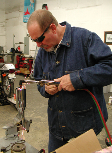
Helluva weekend. Anytime there's lots of motorcycle carnage,sex, whiskey and writing, I'm all for it. Maybe it's Valentines Daycreeping up. Make a note. Here's the deal on the Sturgis Shovelhead. Sincethe engine was in and mounted I went to work on the exhaust system,then seat mounting, position and played with the bars. I made a runto a local steel joint, because I had a notion that I doubt will worknow, but I'm still investigatin'.
Let's hit the highlights. I'm fortunate to have a young,talented fabricator/builder who I'm sharing ideas and resources with.Kent from Lucky Devil Metal Works in Houston is on the phone dailyfor tips and knowledge sharing. It's damn healthy to have someone whois in the trenches daily to assist. In fact I had a couple ofcrucial metallurgy question that morning, but let's hit what Iaccomplished.
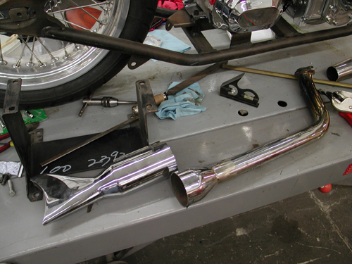
A crucial aspect of building any bike is planning. That'snot to say all my eggs are in a row. We'll see, but the more you canaccommodate, the less redo's will be necessary. Also, don't throwanything away. That junk part might be a critical bracket tomorrow. Idug through my partially organized pipe bin and found a set of oldglass pack, shorty muffler, shot gun pipes. I could use the rear one.I decided, since noise issues are a concern and performance issue area constant priority, I would build a set of shorty mufflers withBandit tuned baffles.

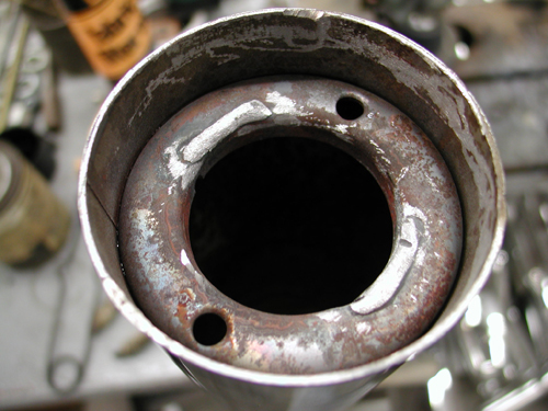
Then I spotted the fishtips in the pile and myconsideration changed. I dug further. Kenny Price from Samson allowedme to dig through his warranty bin when I was looking for stanchionsfor my Bikernet office railing. I remembered touring mufflers withfish tips, I kept digging.
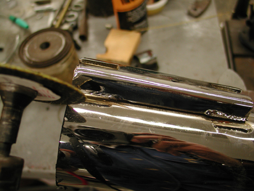
Sure enough I had a set and in quick movesI sliced them into chunks. You know me, I'm a gambler. I cut themwith no methodology in mind past the size and looks, but I came uplucky. Samson designed a baffle system with a cone at the front toguide exhaust pulses into the baffle and it seems to be working fortouring applications. I cut off that portion and discarded themajority of the baffle. But there was still 2 inches of baffle and astandard donut in the rear of the muffler. That's where fate movedit's evil hand over Richard Kimball again. Or in other words I rolledthe dice.
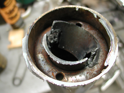
I spoke to Kendall Johnson recently and he told me aboutperformance stepped exhaust systems and reversion cones used to tunesystems at the rear of the pipe. I couldn't make this donut move upand back, but I had the makings of a reversion cone at the stern.With a torch I cut out the remaining baffle, then after speaking withthe HOT BIKE staff member, Craig Murrow, for a reversion cone descriptionI knockout out the remaining baffle, then with various cutting andgrinding cones I formed and smooth departure for the exhaust pulses.Then I had to remove the old touring mounts with a die-grinder andthey were ready to weld.
The rear pipe was comparatively easy since the pipe wasalready made except for the muffler and brackets. Shovelheads arenotorious for louse exhaust manifold connections and tearing out thesingle stud, so I wanted to mount them in the front and rear for asolid, secure connection. The only port for the connection at thefront was the oil bag. That was a bad choice and I'll run a bracket off the seat post before all is said and etched in stone.
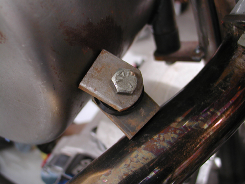
I had to make sure the pipe could be removed with the tabs onthe bottom, then I spaced the tabs apart with a heat sink material. Imay use Teflon, then the notion that the oil bag is rubbermountedfloated to the surface. What bearing would that have on thiscoupling? Hell the frame will vibrate like a mad dog. I'm stillquestioning that link, but we'll see, maybe a spring between the tabs? The final decision was the seat post bracket to come.
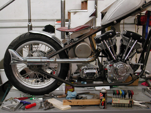
There was one other pipe design consideration–the length.I try to keep the pipes somewhat equal and between 32 and 38 inches.Buster's Sportster runs sharp and crisp with his hand-made 38-inchesfrom the Bikernet Headquarters, as seen in Street Chopper. So Idesigned this pipe to be 38-inches and not protrude past the tire. Mygoal was to make the front pipe curve out the other side and be ofequal length.
At the end of Friday night, one pipe was complete, toolswere scattered all over the shop and I had a couple of Hooker Headerchunks of 1 3/4 pipes segments cut and was fooling with the frontheader. The front was tricky as hell. I wanted to scoop out the leftside of the bike, which added length. I also had a bitchin Rohm Engineering oil filter/cooler system that mounts to the front motormounts and aims the filter at the ground for ease of removal anddraining. The pipe had to clear it significantly. This puppy was alifesaver. I planned to run an oil cooler (Shovelheads run hot) andfilter, for a lasting driveline and more oil capacity. My originalplan called for old school mounting on either side of the oil bag.This eliminated all of that and the plumbing for two elements, the cooler and the filter, wasreduced to one hot looking job in front of the engine for maximum cooling.
I spentall day long on Saturday, dodging the phone and working in thegarage. I had all the tools and materials I needed, even two new setsof welding glasses, which came in damn handy. The trick was to lineup the pipes, make all the right decisions, hope for the best andtack 'em. I did and with a level I constantly compared the pipe tothe top of the lift. The spacing worked out fine.
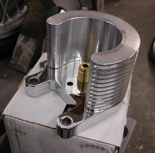
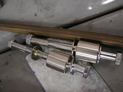
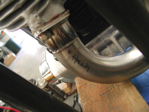
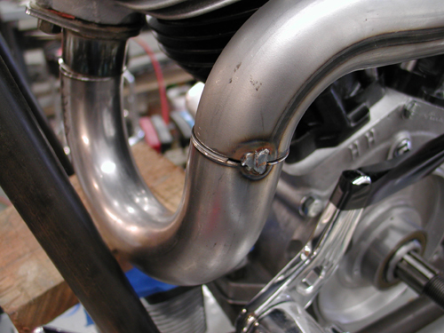
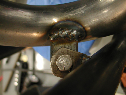
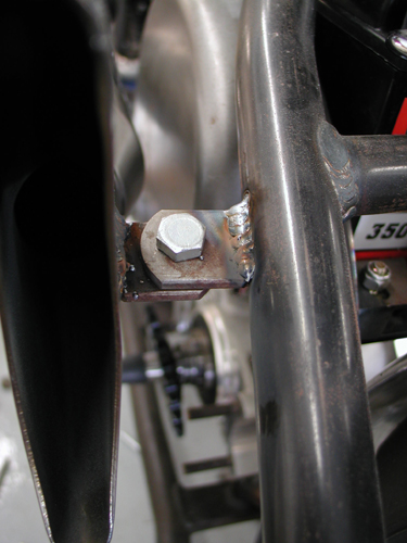
I cleared the top of the Rohm bitchin' oil cooler/filter mounthopefully by enough to allow the pipe slip down and out of the head (I was recommended to use a CCI Filter part number 270126).I tacked the tab with a spacer between the two for some jiggle room.And I made damn sure that the pipe tab was below the frame tab. Atthe back, the muffler was fabricated the same as the other one with aslight exception.
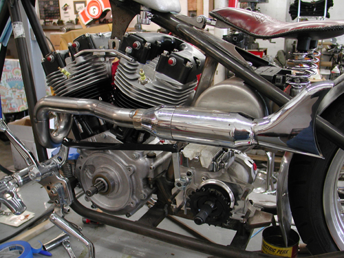
I shaped the reversion cone the same, cut off thetouring mounts and ground the tabs. Then I used a couple of V-blocksto hold it perfectly in line for tacking the halves together. Then Isliced off the crush tabs on the front of the Samson tapered muffler.They were wider and different than the other side, so I cut them off.You'll notice the difference, if you check both side.
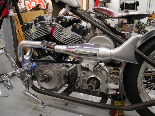
The front parts of the pipe were Hooter elements and theyare smooth mandrel bent segments. I used another one for joggedstraight piece between the muffler and the head. I took the 13/4-inch exhaust to my Muffler Master bender and bent it slightly oneway, then reversed the sucka and bent it the other way. It fit like adream and looped out enough to pass the oil bag. I used Hooker headeralignment sleeves to hold the front pieces in perfect alignment. Donedeal, I tacked them, constantly comparing the level with the lift,the pipes then the muffler. After the tacking was secure, another tabwelded to the frame, avoiding the oil bag (a Lucky Devil concern,since the oil bag is rubbermounted), then all elements wererechecked, I removed both pipes and MIG welded them as complete aspossible.

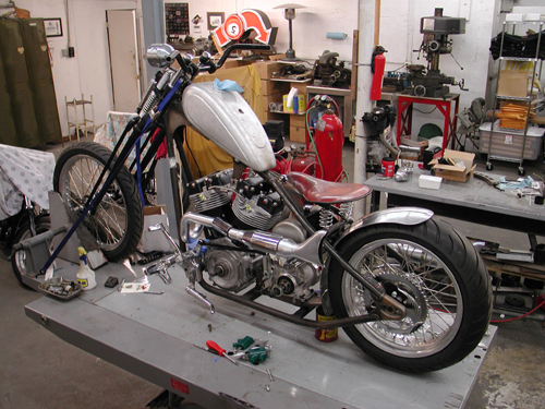
I find that MIG welding is a pain and blows holes in pipes easily.I also discovered that after I MIG weld a pipe I can flow the weldeasily with a torch and smooth out all the welds, fix holes and fillgaps. I actually found a piece of old steel rod, not much bigger thana piece of wire. I usually use old coat hanger, but it pops andwheezes from the paint coating.

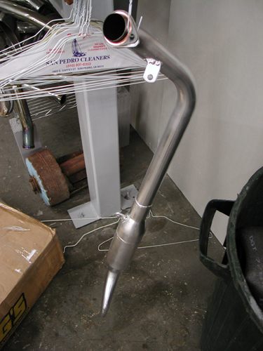

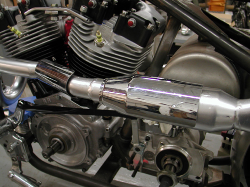
After the pipes were welded, flowedand checked twice, I ground all the surfaces with an emery disc andpainted them with whatever barbecue heat paint I had laying around.The lovely Layla is currently on her way back from Home Depot withsome flat black heat paint. We'll see how that works.
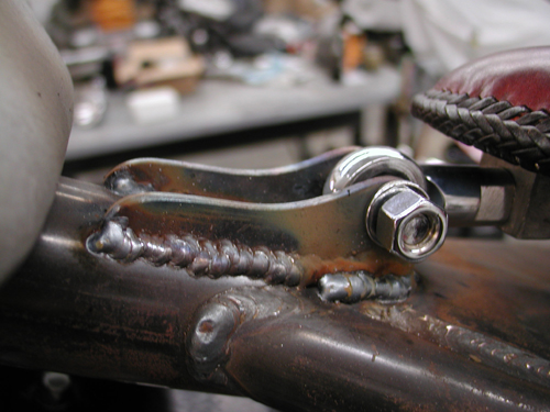
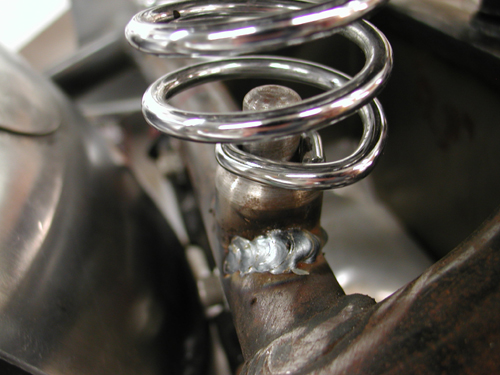
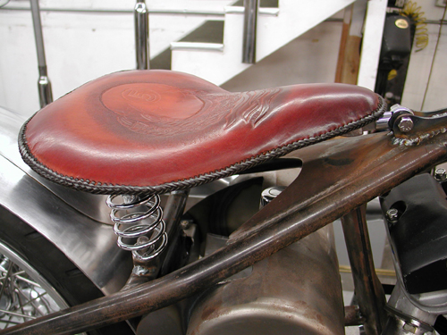
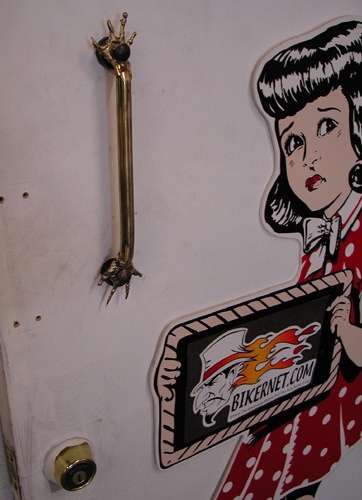
Kent from Devil hand fabricated the seat pan, brackets andbungs. I set them up and welded the parts in place. Then it was timeto roll the bike off the lift and see how she fit and where I mightneed heat shields. I discovered a couple of things. Yes, the scootwould require left side heat shields and nothing on the right. I alsotested my notion to sculpt claws out of brass, unsuccessfully.
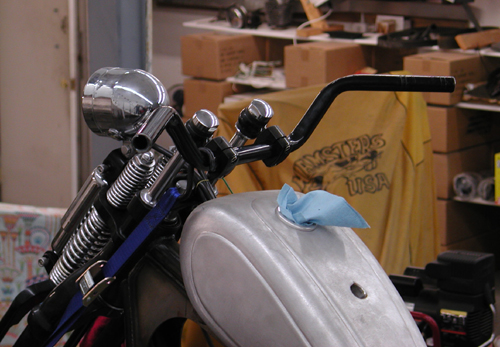
I also found that the existing bars wouldn't cut it. Igrabbed the old '48 Panhead TT-bars, narrowed them by 4 inches, and Isorta like them.
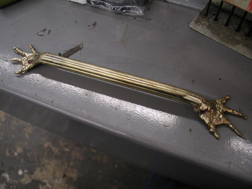
Okay, so I grappled with the sculpting business fora couple of hours and discovered that I can't control the brass likeI can steel. I spoke to Kent from Lucky Devil and he recommended thatI try TIG Silicon Bronze rod. I'll try that next week. In themeantime, my first brass sculpting attempt ended up on the shop door.Let's get the hell out of here.
Ride forever,
–Bandit

Sturgis Shovel Part 6
By Robin Technologies |

Here we go. I’m relunctantly behind the eight ball, or more likely the 5-Ball in this case. The bike is nearly complete and I haven't caught up with the articles. For the most part I was working at Primedia on the bike mags and didn’t have time to breath. No fucking lame excuses. Let’s hit it.
My original plan called for brass sculptures to hang this bastard together in a purely Bandit way. I messed with some odd heavy brass cloverleaf rod that was over a ½ inch in diameter. I wasn’t having my usual creative luck with bending or messing with this material. Kent from Lucky Devil Metal Works in Houston recommended that I use silicone Bronze rod and I’ve since messed with it. I shifted gears from Gargoyles and sculptures to pure mechanics. I started drilling holes is everything.
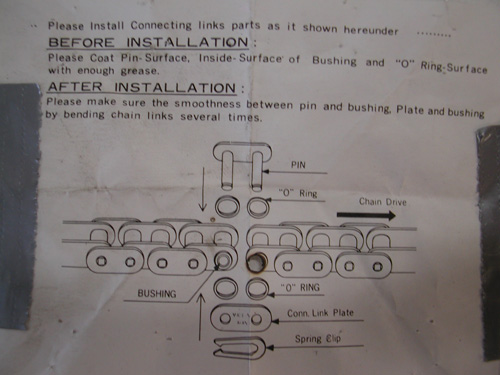
I discovered a piece of ½-inch wide strap that I thought was copper. Remember that the notion behind this mess is to use as much bare metal as possible. As it turned out the strap was brass so I gave it the Scotch Brite treatment and went to work. Before I made or positioned the rear Custom Chrome chain I needed to align the wheel, the transmission and the engine. I used my BDL inner primary and pulled the loose engine and tranny into position. Then I centered my chain axle adjuster and installed the chain using the CCI instructions (above). I have an old chain breaking tool, so I took out just enough links.
With the chain in place, aligned and adjusted the wheel using the Doherty wheel spacer kit (a life saver). I couldn't mess with the requisite chain guard until all was in the correct groove. Although the Paughco custom frame is designed for a belt, I choose the old school route and it worked out well. Lots of extra space to mess with.
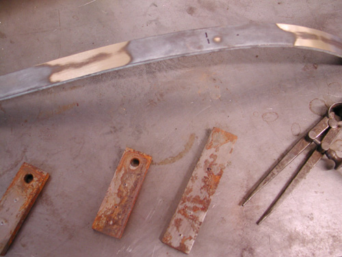
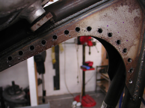
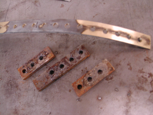
I dug through my drawers of tabs and crap that I’ve had around for 25 years. In the old days Mil Blair would call me from Jammer from time to time and tell me when it was time to shit-can scrap iron. I picked up tabs, spacers and brackets by the fist full and I’ve been moving them from place to place ever since. But damn, when you need a tab it’s bitchin to find just the right size in a drawer. Since I was going nuts with the drilling treatment, I matched the work on the frame with holes in the chain guard and counter sunk the edges for a more rounded look.
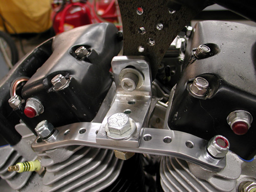
I also hit the top motor mount with a similar treatment. To give it a bit of consistency I measured from center to center on the holes and made all the holes the same diameter, 1/4-inch.

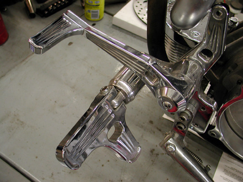
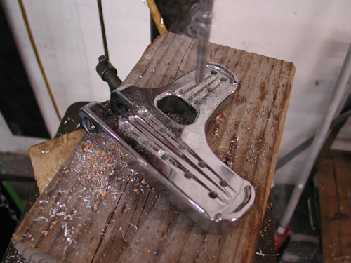
The hole deal became an obsession. I started drilling ¼-inch holes in everything including the Joker machine foot controls. I also went after Russell Mitchell’s Scotch Brite code. I swallowed hard and rubbed a piece of chrome with the coarse material and discovered that chrome reflects everything until it’s brushed with the wiry fabric. It gave it a raw material appearance and I decided that it was cool but a pain in the ass to do.
Again, I drilled the holes the same space apart, ¾ of an inch. It’s not always that easy, though. Sometimes the formula just doesn’t work. I use a pair of calipers to hold and mark the distance from hole center to center. If a hole ends up being located too close to an edge of the material, I back off and try another formula. Make sure to plan before you start drilling.
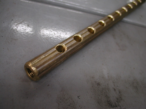
Here’s that damn brass stock. I was determined to have Brass, Copper, Stainless, Aluminum and a bare metal effect on the frame. You’ll see shortly how it worked out. I couldn’t bend that brass shit without destroying it, so I made the shift linkage out of it. I cut it off on a bench lathe and drilled and tapped the ends to 5/16 fine threads to fit the fine thread heim joints. Then I drilled the rod and countersunk the holes to remove the sharp edge.

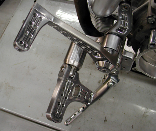
Here’s one of the Joker Machine control sets, rubbed with Scotch Brite and drilled. They make fine controls, some of the best. You can adjust these puppies anyway you choose to fit your riding position, inseam or foot angle.

Before I leave this chapter I’ll touch on this new petcock from Spyke. It’s incredible, if it works well. It’s designed to give you every option for positioning and spigot direction. I ran into only one problem. No wrench lands to help tighten the bastard.
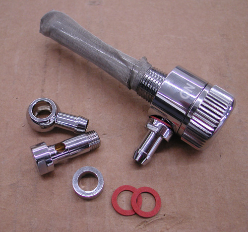
Check it out. You can run it faced in any direction and still read the switch locations and turn the knob without a lever smacking the frame and components. The spigot set allows builders to face the gas line in any direction.

I used the straight spigot and took off one of the fittings because my tank threads are female. The only problem I had was tightening it down, but I’ll get to that after the powder coating returns from Foremost Powder in Gardenia, California.
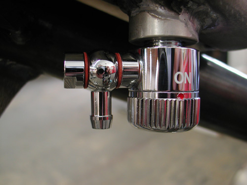
This puppy will revolutionize the industry for petcocks, if it works. I’ll let you know in a week or two.
Ride Forever,
–Bandit
Sturgis Shovel Part 8
By Robin Technologies |
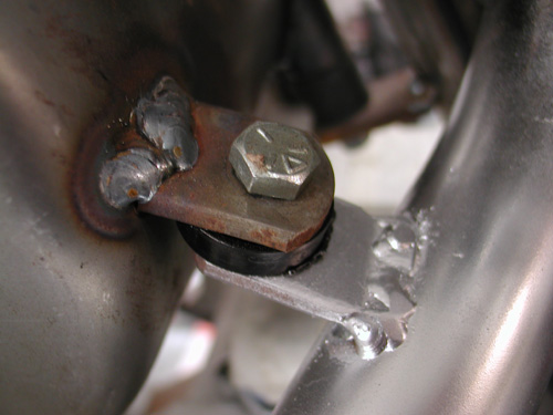
My first move began with a correction. I removed the exhaust pipe tab welded to the oil bag. The oilcan is rubber mounted, the exhaust pipe generated severe heat and the pipe system needs to be solidly mounted. It had to go. Actually Kent from Lucky Devil Metal Works in Houston tried not to mention the false move, but his frown gave it away. Or was it that question? “Is your rear pipe really mounted to the fuckin’ oil bag,” Kent said tentatively?
I discovered that the pipe exits the head close to the seat post and worked on a pipe connection there. There are a couple of rules in making pipes that I need to abide by. I needed to remove the pipe once in awhile, so I needed the pipe tab to be on the outside of the frame tab. Often mounting required slack, so I dug around for 1/16-inch washers to run between the tabs. That way when the fasteners are removed there’s some slack to pull the pipe free.
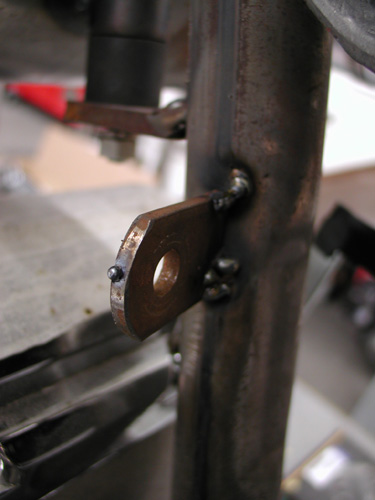
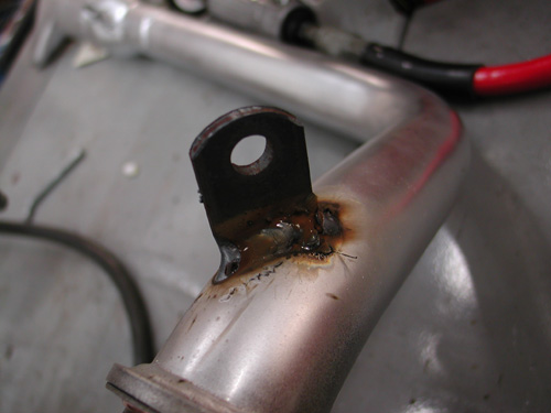
I worked with the pipe fully in place then tacked the seat post tab. Below is the tab tacked to the pipe. Then the tab welded in my shitty MIG welding fashion. I should slow down and clean the base metals more. I generally grind a bevel into the tabs for greater weld penetration. The welds are strong, just not handsome.
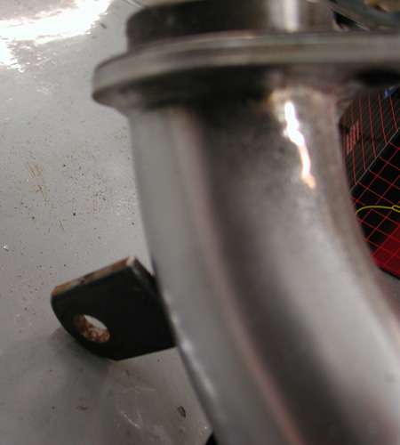

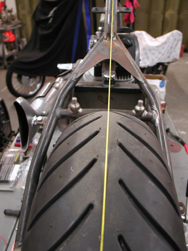
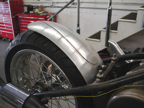
Next I needed to attach the Lucky Devil rear fender, align the rear wheel and cut the chain to fit. But first I needed to center the wheel in the frame, sorta. The custom Paughco frame is designed and manufactured to hold a belt pulley and a 180 Avon Tyre. That prevented me from measuring between the frame rails. I needed a straight line down the center of the frame backbone. It’s not incredibly accurate but close to draw a fabic or nylon line down the tube. Then with Doherty space kit and the seal spacers that came with the Custom Chrome aluminum and stainless spoke wheels, plus the Brembo brake caliper bracket, I aligned the wheel.
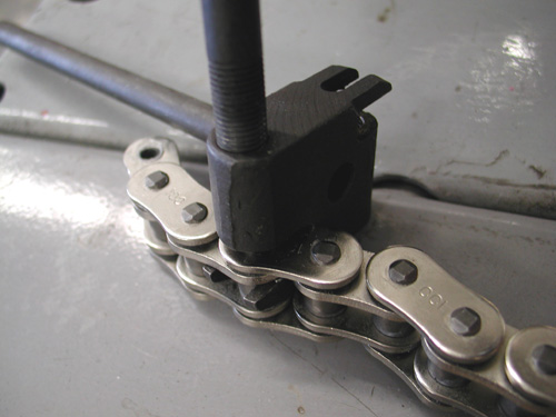
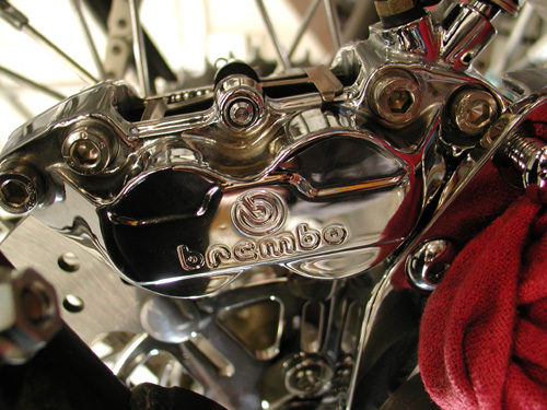
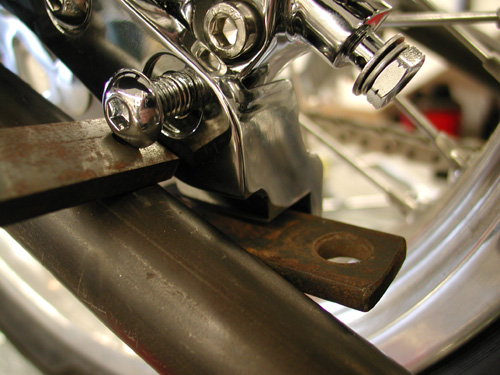
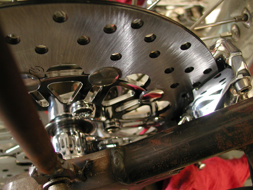

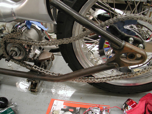
Before I cut the Rev Tech chain I installed the BDL Belt inner primary and pulled the engine and transmission into place which determined exact spacing. I know I covered this aspect somewhat a couple of chapters ago. There’s been some heavy drinking in the meantime, so if I lose track, it’s on Jack.
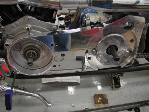
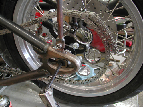
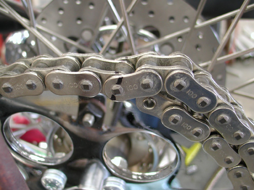

I centered the wheel in the chain adjustment slot to give me slack either way. Then I finally cut the chain with a JIMS tool.
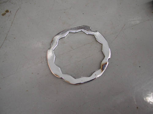
I spoke to a couple of guys about sprockets and was told that this contraption will hold a sprocket nut from coming loose better than simply Allen screws in the Custom Chrome sprocket. I may use it or not. Haven’t decided yet.

The reason this is altered is that it’s for a pulley and a different era. Add that to the fact that I flopped the dished sprocket over to space the chain away from the tire. That aspect worked perfectly.
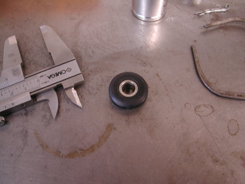
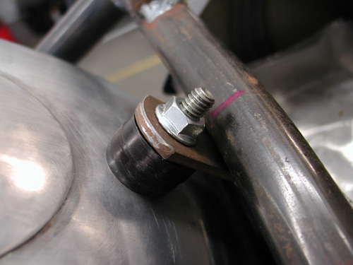
I decided that since the tank was rubber mounted and aluminum won’t flex as well as steel that I would attempt to rubber mount aspects of rear Luck Devil fender. Kent designed and handmade the fenders to match aspects of the XR 750 tank.
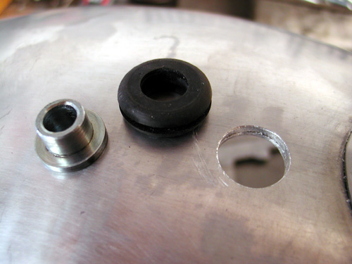
Cyril Huze sent me several grommets to work from and this pair are from some late model Sportster application. I measured the O.D. on the center portion and discovered that I needed ½-inch holes in the fender which I drilled after I had mocked up the fender in place, ground a clearance strip for the chain and stood back several times. Arlen Ness once told me that he used a chain wrapped over a tire to space a fender. I needed enough space for fasteners under the fender and some chain adjustment slack either way.
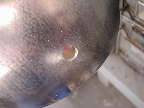
I moved the fender up and back, and side-to-side several times before making any hole-drilling marks. I was a nervous wreck. Ya don’t mess with the Devil’s fender. I finally drilled a half-inch hole, and smoothed the edges, in the bottom of the fender then at the crossover tube. I worked in the rubber with a dab of oil and bolted the bottom stainless bolt in place.
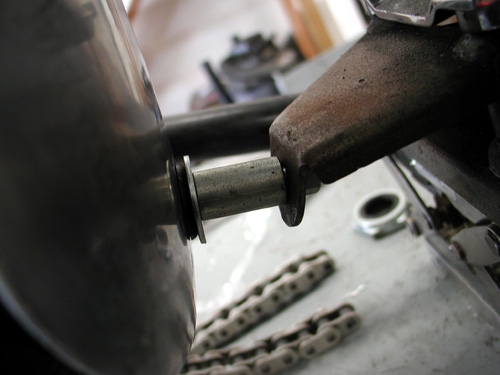
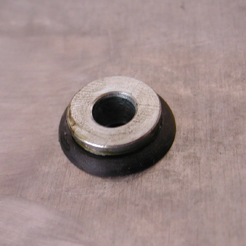
The Sportster grommets have metal inserts, which make them easier to install. With a couple of spacers in place the fastener held the center tab for tacking.
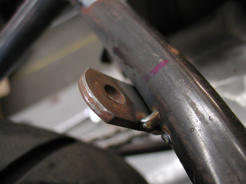
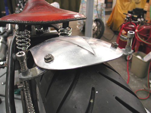
Here’s where it got tricky. I’ve been bending metal with a torch for years. Never improved my technique. Just the other day, a month after I built this fender rail system, I bought a small strap or tube-bending tool. Wish I had it when I went after this project.

First I built the fender strap out of a piece of exhaust pipe bracket. It came with two 3/8-inch coarse tapped inserts in each end. My plan was to build a fender rail system with tubing so I could adapt a couple of running lights on the tips. I carefully bent and drilled the strap and fender.
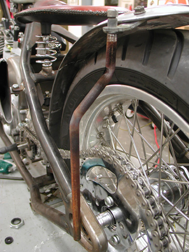
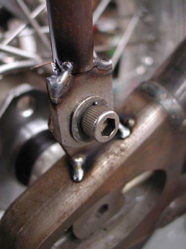
Then I bent the tubing fender rails to fit over the chain and tacked tab to the Paughco frame. One item I often attempt to use is a level. I’ll level the frame from side to side, then strive to keep all the other elements level. It helps.
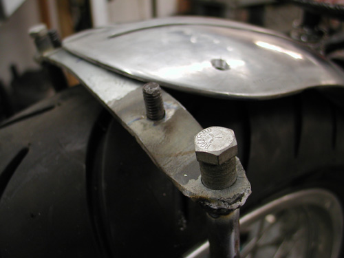
Here’s a perfect example. As I finished my welding chores, I got on a roll. I thought– wouldn’t it be cool to weld the fender bolts in place from the bottom. They would never come loose. Note the angle. There was no way they would ever return through their mounting locations. I was forced to grind them off and clean the holes.
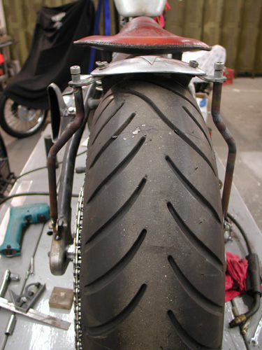
Here’s the finished fender rail system. I drilled holes in the frame and the rails to run wires. I still haven’t found the perfect running light style that rocks my boat and will afford me enough room to use the proper fasteners. Hang on!
