Road King 11/08/05
By Robin Technologies |

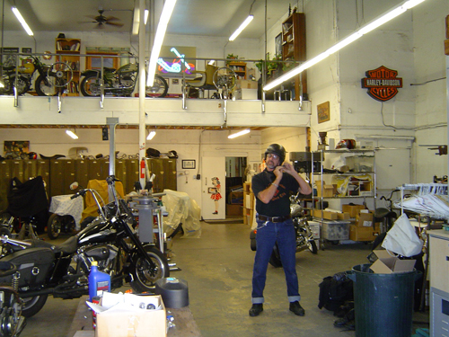
Around mid June Kerry and myself were organizing our trip to Sturgis, when Bandit contacted me an asked how would I liketo ride the Road King to Sturgis. Immediate thoughts were Wholly Shit, I’ve read all about the King on Bikernet and watchedthe different stages Bandit has put it thru, so I was very familiar with it, and for Bandit to be asking me was really a big deal, meaning, I felt honored enough when Bandit invited Kerry and myself to join them on the ride, let alone ride his bike. So youprobably guessed the answer was a big >>>>>> Yes Sir !! thank you very much.
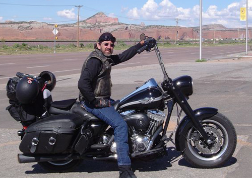
For the readers who aren’t familiar with the Road King, I’ll enlighten you. It started life as a stock 2003, 100th Anniversary model.Bandit said he designed the bike be a big bad assed, blacked out touring bike with heaps of attitude. Bandit and his crew wanted to use as many H-D parts as they could to prove you could build a mean assed bike out of Harley Davidson’s catalogue. They started by blacking out the dash, a set of one inch lowered air shocks and a detachable back rest along with some neat touring components. With the help from a dealer for some more involved tech mods to gain horsepower and some low-down torque, they came up with a formula by adding performance cams, Screaming Eagle Heads, air cleaner kit and two into one pipes powder coated black, giving them 68 horses compared to 60 and torque was 76 pounds with a 6 pound increase. Next they installed a factory oil cooler which Bandit tested on a run to Barstow saying how it kept the oil at a very reasonable temperature which is critical for long term, Twin Cam reliability.
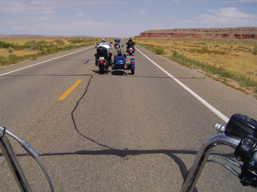
Fast forward to Sturgis, August 2005 and Kerry, my wonderful bride, and myself arriving at the Bikernet Headquarters being greeted by Bandit and the lovely Nyla. We were enjoying a beer while having a grand tour of their unbelievable home when Bandit said, “Get ya helmet Goddamit, we’re going for a ride.”
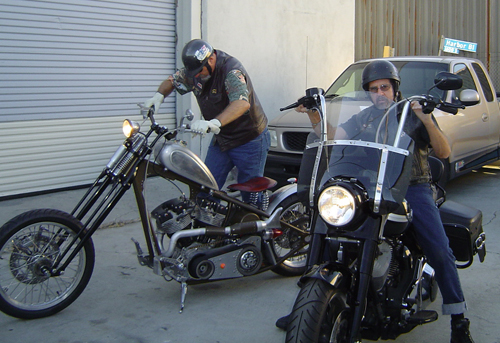
It’s hard to explain the excitement that was welling up inside of me, especially when I first laid eyes on Bandit’s bare boned, mean as shit Shovel, I swear it had a look like, let’s go, I’m ready. And right beside it sat the Road King.
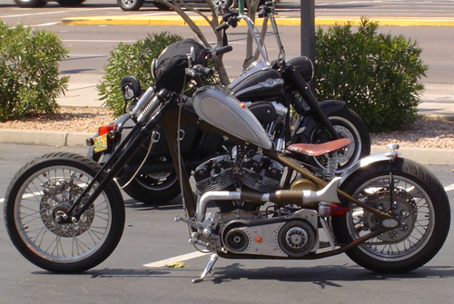
It definitely looked like itwas ready to do some very serious miles, man. It looked beautiful, all blacked out like a road warrior ready for action, 16-inch apes reaching for the sky, a very comfortable looking seat and a detachable back rest for Kerry. I gotta tell you these two bikes were like chalk and cheese, the Road King had all the creature comforts and Bandit’s Sturgis Shovel had absolutely nothing, excepta little back fender and a sprung seat, Shit !!! and he’s riding it to Sturgis, tough sonofabitch, I thought to myself.
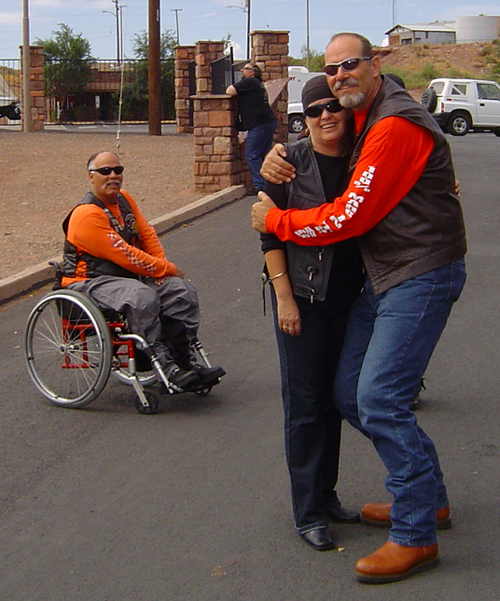
Just as the sun was setting over Long Beach we fired those puppies up and peeled out of the Bikernet Headquarters like two crazed maniacs going for their first ride after a long cold winter, ( sound familiar Bandit ). Seriously thou, we cruised around Long Beach taking in the sights and both of us getting used to our rides. We both had grins from ear to ear, especially when we twisted the wick on these babies, I was blown away, the King with it’s sheer size and weight, had some serious acceleration, man. I was impressed plus having a lot of fun and Bandit’s shovel went like a rocket, with it’s power-to-weight making it an awesome ride.
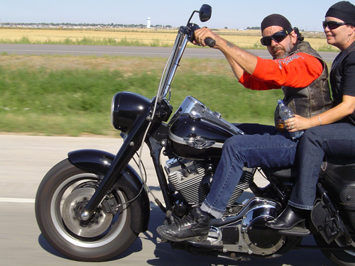
This was going to be my 4th trip to Sturgis (beginning in Australia) and I knew 100 percent this trip was going to be very special, I was feeling right at home on the Road King, everything was perfect except for the bloody windscreen, I think it was set up for Bandits 6′ 4” frame and I could not get used to it, but Harley had it covered. Two seconds and it was off, no problem.
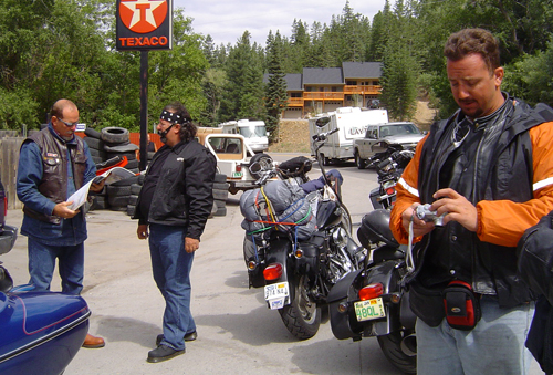
I would love to tell you about our trip to Sturgis, but it’s been covered by Bandit and Johnny Humble, the young gun from Texas, both really great stories and you can still check them out by going to The Events Coverage in Bikernets Department Site.
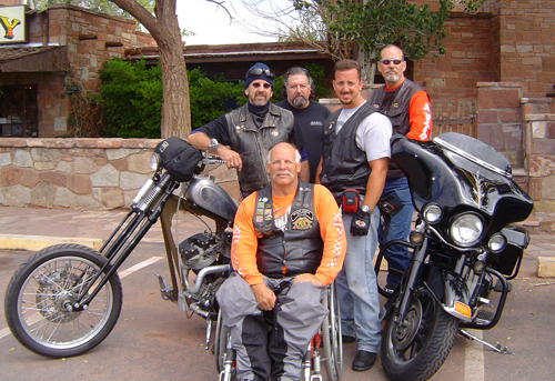
It’s hard to put into words, the true feeling of this road trip with such great company, I will say that we were very privileged to get to ride with them, even thou we live on the other side of the world, I know that Kerry and myself have forged life-time friendships and hopefully will get to do it again some day.
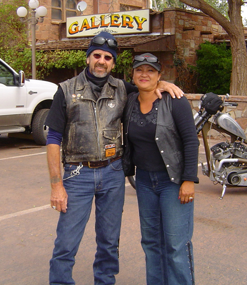
I have been privileged to ride a lot of bikes in my time and I must say the Road King was bloody brillante, we covered 4000 miles all up, came across all types of weather (as we all do) including high altitudes where the King never missed a beat with it’s superb fuel injection and very smooth motor. Seating was great, and I just loved the apes. Not only do they look really cool with an attitude, they were really comfortable.
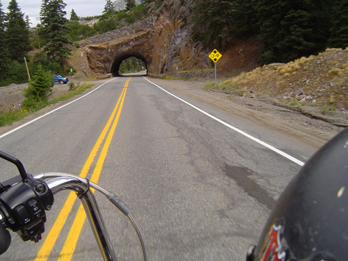
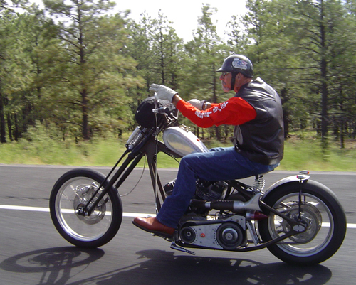
I will post some photos of our trip that you haven’t seen and would like to do a follow up of our trip from where Kerry and myself parted company from the rest of the crew, returning to L.A. via Denver, Santa Fe, Sedona and Vegas.

I would like finish up by thanking Bandit and Nyla for their friendship, hospitality and giving us such a great time, not forgetting the use of their Road King.
Okay guys thats a wrap, hope you like it.

Road King 12/04/02
By Robin Technologies |

Yep, these techs will be backwards. I just rolled in fromArizona after the first 1,000-mile test ride after installinghighbars, performance parts, and modifying the windshield to fit thehighbars. So why publish the techs backwards starting with thewindshield? We’re lazy. This one will be short and the next two,since Frank Kaisler was involved, will be mammoth techs withthousands of photographs. Hang on for them, but if you’ve installedhighbars on a Softail or a King model and have long arms like myself, the windshield may be a problem to attach, but there’s acareful, simple cure.
First put the shield in place and decide if you can endure ahandlebar adjustment or not. If you pull the bars back in line withthe front end, the windshield will fit without a problem. You mightcheck it for 80 mph flexing which could cause rubbing against thebars, cables, brake hoses or wiring (if you didn’t run the wiresinternally). I took short wire ties and held small soft stripes ofrags around the cables that would have been damaged.

So I shoved the bars forward until the windshield would havefallen off the front-end. I’m not a big fan of windshields, but whenyou plan a ride through a 1,000 miles of rain, cold and wet highways, it’s a plus. I used the adjustable windshield from Harley-Davidson which allowed me to raise or lower it. I discovered that the lowered position is actually more comfortable in the rain. If I had raised it, I would have looked through the shield which was scattered with water and streaks. Visibility sucks and distraction wasoverwhelming, so I lowered it and my visibility was perfect while stillmaintaining the comfort and protection of the shield.

So what the hell did I do? I cut scallops in the plasticshield. First I marked off the area of the shield that had to beremoved with 1/4-inch masking tape and began to grind through theplastic with a bench grinder, the finer of the two stones. I tookcare to keep the edge of the plastic aimed down so the stone wouldn’t grab the sonuvabitch and crack it. I ground one corner then the next to search for a basic rounded feel. I avoided sharp edges or grooves that could crack. Since this was no perfect established science, I took my time slicing notches then slipping the windshield into place. I went back and forth to the grinder over and over. You might want to wear a breathing filter during this process and eye protection.

Once I was close to the finished area on one side, I took thewindshield to the vice and with leather pads on either side of themounting bracket clamped it down. Then with a high speed drill and a burr bit began to cut and shape some more. This, I found was difficult and took care not to allow the bit to grab and cut into theclear surface, but I was able to clean the edge some more. Ire-installed the shield again and determined that I was damn close.

Keep in mind that this was a last minute operation onThanksgiving day, between writing projects and packing for a run tothe desert. As the evening closed in it began to rain, a rarity inthis neck of the woods. I jogged in the house and flipped on theweather channel. The gods of the Roulette table had decided that Iwas not supposed to ride this weekend. The only rain east of theMississippi was dead over the 10 interstate from Los Angeles to theArizona State line. That made the windshield project even moreparamount. I dashed back to the garage.

Once I was close to the necessary fitment, style andprecision matching became a consideration. I ran a piece of maskingtape up the side of the stainless steel strut straight up the shieldas a measuring guide. Then I measured up from the horizontal strut to where the cut began. With these measurements I was able to compare them on the opposite side for an even scallop into the shield. I went back to the grinder and to the burr device for the final shaping. I continued back and forth a dozen times from the grinder then the high speed drill and back again. Once I had it nailed down, predominately with the grinder, I used an emery bit to smooth the edge of the Plexiglas.

That completed the cutting and shaping although the unitdidn’t lock entirely into place. I knew that once on the road thewind would prevent it from escaping. One small wire tie held thespring lock on the detachable windshield to the clutch cable foradded insurance. Just under 1,000 miles later I pulled back into SanPedro with a completely successful ride under my sore ass, provingthat careful mods to the Plexiglas windshield are completelypossible. Rah, rah.

Saddleman Improves the Amazing Shrunken FXR
By Robin Technologies |

SADDLEMEN MODS TO THE SHRUNKEN FXR–In a world where over promising and under delivering has become all too common here is a gem I must share. The Bikernet built Shrunken FXR has become my daily rider and needed a couple small adjustments to be just perfect for me.
One detail was the too small seat or the bike was too fast (pick one). So I rode my bike over to meet the nice folks at Saddlemen and see what they could do to help me out with my seat. Upon arriving at the Saddlemen facility I spent time with guys from the front office to the guys in the shop ( all of whom took great interest in my motorcycle and the seat they were going to design and build). I noticed from the get-go these people were all riders. I shouldn’t be impressed by that, but there are so many folks in this industry who don’t even ride anymore.
We discussed what I needed (lumbar support) and a lip on the edge of the seat to keep me from being bucked off or sliding onto the rear fender. We also discussed the lines of the bike and that in the case of the Shrunken FXR , less was more. After the team and I spent a great deal of time figuring out what we wanted and didn’t want I was able to walk around the shop and see the whole seat making process from start to finish. man was I impressed!
So many talented folks all working together to put out an amazing array of products designed by and for riders! It was a real treat to see this and made me truly appreciate what they do much more. Great companies, in my opinion, are made of the people who work for them. So I left my bike for mock-up, and received a call back in a week.

When I showed up I saw the foam of the seat had been formed and pan had been constructed. We discussed coverings and stitching, again less is more. They got it and even pointed out to me the lines of the bike would be reflected in the seat.

Three days later I returned to pick up my bike and see my new seat! A seat is the finishing functioning touch to any motorcycle (much more than something you sit on) it must reflect the bike while being comfortable and a key suspension element.

I was so happy to see the seat. It looked amazing and really I could not have imagined it any better than they had built it. I put my helmet on, thanked them and jumped on the bike to ride away. First thing I noticed was the lumbar support made the bike so much more comfortable to ride and kept me in the perfect position to reach all my controls.
The biggest difference was when I hit a huge pot hole (tons of em’ in area) was my ass stayed firmly planted in the seat and the impact was minimal. The seat made my bike complete.
Can’t say enough about how impressed I was with the Saddlemen crew and facility, in short they made my custom bike have a perfectly functional and stylish seat. The perfect blend of function and form. I suggest anyone who needs a seat built or customized give them a call. They are a family team of bikers designing and building products for bikers. I like it!
–Buster
Mudflap Girl Part 4, the Spitfire Frames to Rollers
By Robin Technologies |
Suddenly we’re smoking on the Mudflap Girl FXRs, but the week after I received the frames, I had to jump a plane to New Orleans and ride a Victory to the Smoke Out. I was itching to work on these bikes.

I survived the Smoke Out, and since I just spent 1000 miles in a Victory saddle, I was motivated to get back in the wind. We looked down the barrel of the ticking calendar as I returned from the East Coast on Sunday and Monday the 27th of June I stepped back into the Bikernet shop and faced two Mudflap Girl FXRs on lifts ready to rock. I dove in making lists and started to assemble my frame and the Spitfire girder front end.

Building a bike is like falling in love. We all have our dream of the perfect woman, and each time I build a bike, that notion is the driving force. I’m building the perfect romance, with all the best intentions. I want this one to last forever, take me anywhere I want to go, and be my Mudflap girl baby in spirit, appearance, and function.

I would imagine the same mental scenario applies to a home building architect. In fact, we have focused some of our efforts on creating a vintage motorcycle coffee shop in the front of our building, Bandit’s Barista. Talk about a daunting process involving several city agencies. Let’s leave that one alone. Sin Wu came to a meeting this morning and immediately quizzyness engulfed her and she was forced to leave. “It’s too daunting,” she said.

We are so fortunate to be able to rely on our friends and compadres in this industry and build whatever motorcycle we want, then go for a ride without severe governmental restrictions. Meanwhile, back in the shop, I was completely astonished at Paul Cavallo’s talents and shop capabilities. He designed and manufactured every element of this classic girder front-end. As I installed his internal fork stops and began to assemble the front end with the Foose-designed MetalSport 2D wheel, I was constantly blown away at every intricately machined piece.

Although Dr. Willy bitched about the top motormount on the frame, I didn’t have a problem with it. It just forced us to face another brief obstacle, which will ultimately create a very cool linkage issue with a 7/16 pivoting rod end on the top like most FXRs.


But I’m getting ahead of myself. I installed the fork stops, then the Biker’s Choice neck races, the Timken neck bearings, and the Metal sport front wheel on the Spitfire ¾-inch axle. Paul set up his frames to take stock Harley 2000-2007 front and rear brakes. We are going to use factory brakes on my son’s FXR, but I’m running with GMA brakes currently manufactured by BDL.


I had to come up with a mounting system using Paul’s stock H-D brackets. It was a trick but worked out, with brass rod and steel spacers. I messed with it for a couple of hours. Ultimately the GMA caliper was centered over the MetalSport rotor and in a terrific position for bleeding.


Then I started to install the girder rockers and bronze bushings. I was careful to grease every component, and again I was impressed by the precision fit with each bushing and axle. I installed the trees on the fork stem and rolled closer to installing the girder structure. Everything just slipped together.


Unfortunately, I was missing one element of the front end, the brackets holding the shocks in place, so I shifted to something fun, installing mudflap girls on the Spitfire side panels. They make these Zeus fitting fastened aluminum panels out of street signs. The mudflap girls came from 2Wheelers in Denver, but the Arlin Fatland and Donna team is currently headed for Sturgis to the rally, which reminded me that Sturgis is just around the corner. If I had another month, we’d be riding the Mudflap Girls to the Badlands.


Next, I needed to install the rear MetalSport wheel and driveline. FXRs are tricky in this regard. The entire driveline from the engine to the rear wheel needs to be installed at the same time. We started with the swingarm, using the Custom Cycle Engineering swingarm axle and retrofit kits. Here’s what CCE says about these conversion kits.

SWING ARM RETROFIT KITS
Custom Cycle Engineering has developed a swing arm conversion kit that replaces the stock Cleve Bloc style swing arm bushings with spherical bearings. The conversion covers all the FLT and FXR models from 1980 to 2001. The swing arm conversion kit coincides with Harley-Davidson’s change from the Cleve Bloc bushing to a spherical bearing in all the 2002 and up FLT models.

The conversion over to spherical bearings in the early models dramatically changes the handling and tracking of all the FLTs and FXRs. The sticksion at the swing arm pivot is greatly reduced with the new spherical bearings. This allows for the swing arm to react quicker to any harsh road conditions, keeping the wheel in contact with the road. The use of spherical bearings also helps negate any lateral and torsional movement in the swing arm by the shear dynamics of a spherical bearing.

The swing arm bearing conversion kit is one if the positive answers to the inherent ill handling problems of the popular dresser models.

It was easy to install the new spherical bearings using our shop press and the special tool CCE provides with their kits. We pressed them into place with the CCE guide tool and red Loctite. Then we installed the swingarm on the transmission and the whole tamale in the frame, since the oil tank was out for sealing and some flat black protection. Ray C. Wheeler gave me a hand. We slipped the JIMS transmission and swingarm through the back of the frame sideways, then turned it level and aligned it with the frame mounting system. My son scored some used bare aluminum cleave blocks, and I ordered new H-D rubbers from Biker’s Choice. Watch how the rubbers and cleave blocks are mounted. They are like a small four-piece puzzle with guide pins in particular locations.


With the JIMS 6-speed transmission in place, we jacked up the trans for engine installation. With a centered Biker’s Choice front motormount bracket in place and the rubber biscuit we were ready to rock. Willie helped guide us through the process. Willie is a master with FXRs. He’s worked on bikes, and rebuilt engines and transmissions forever. He knows all the tricks.

With the driveline in place, I started to monkey with the D&D pipe mounting, mounting brackets, and mounting the GMA rear brakes. The brakes became tricky, since Paul designed a tougher and wider swingarm, but it worked out perfectly. I’ll get to that puppy in a minute. I noticed that the trans didn’t come with the final seal and locking nut, plus we needed to reach out to JIMS for a proper offset sprocket for the 180 Avon tire. Since this is an 80-inch Evo, I wanted some gearing advice for the 6-speed overdrive transmission.


Here’s what James Simonelli wrote while packing for the Sturgis Rally and preparing for their install facility. Call them quick, if you want an upgrade while you’re in town.

MUDFLAP GIRL GEARING ADVICE FROM BAKER DRIVE TRAINS–
22-51 with normal 37-24 primary is 3.57, pretty lively! In 6th (.86)
you would have 3.07
23-51 37-24 gives 3.42 and 2.94 in 6th. I think that’s where I’d start.
To compare, most stock late models with 70/32 belt and 36/25 primary are
3.15 overall in 5th.
It’s nice to be slightly below 3.0 in 6th for 75 mph cruising. If it’s a
stoplight burner, go the other way.
Baker will be set up in Sturgis on Lazelle performing installs. If you would like your 5-speed modified into a 6-speed, or a special Baker oil pan added to your dresser, set up an appointment soon, and tell ’em Bikernet sent ya.


We ordered a rear sprocket spacer and a dished 51-tooth sprocket from Biker’s Choice. It’s always somewhat a roll of the dice and I try to build a selection of spacers to allow me a variety of spacing options. With the JIMS ½-inch offset 23-tooth sprocket and the centered wheel, the transmission lined up perfectly with my brand new O-ring chain. It had never been removed from the crumbled box after a trip or two to Bonneville. I pulled it free from its container and the bastard was covered in rust.

Chad from JIMS sent me a photo of the mainshaft seal-installing tool. I also ordered the seal spacer, but had an installation question.

“Tech says bevel side faces into trans,” said Chad. “I have attached an image of the
needed tool, #786.” I dug through my special tool bins and found something from JIMS that would handle the trick.


In the meantime, our sheet metal returned from Jim Murrillo, who sealed the tanks with Caswell and gave the exterior a protective primer coat. It was a rush to slip the two gas tanks into place but we ran into a problem with my oil tank. I almost had to take the engine and the trans out of the bike to return it to its rubber mounts. Ah, but we succeeded.


Now all the major elements are in place, but the Sturgis Run is moments away. We plan to load my Sturgis Shovelhead onto our trailer, with the 120-inch Panhead, the Salt Shaker for Mr. Wheeler to ride. We will snap the trailer to the Bikernet hearse and cut a dusty trail in a couple of days. While I’m in the Badlands I’ll be thinking of Mudflap Girls and getting back to the builds. I’m sure I’ll return with more ideas, and next year will be the year of riding FXRs to the Badlands.


Hang on for the next installment as we mount up the Trock-modified CV carb on my ride, and the Mikuni 42 mm on my son’s bike. We have wiring harnesses from Wire Plus, and I have a rare intake manifold from H.E.S. and Branch, that was ported by John O’Keefe. We’ll be rolling close to final assembly as I install my BDL belt drive system and Frank’s mid controls. Goddamnit, I can’t wait.

Sources:
Spitfire
Biker’s Choice
JIMS Machine
MetalSport
BDL/GMA
Wire Plus
Branch O’Keefe
Bennett’s Performance
Custom Cycle Engineering
The Amazing Shrunken FXR Project
By Robin Technologies |
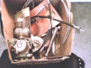
This here cardboard box full of odds and ends was where it allbegan. Or was it just an idea? Or maybe too much Jack Daniels. Ormaybe Bandit was tired of me whining about it. Anyway, like a beggar on the streets ofCalcutta, or Blanche Dubois in “A Street Car Named Desire,” I depend onthe kindness of strangers. And there ain’t none stranger than Bandit’scohorts. Strange but mighty generous, such as Rogue, who cut us adeal on the FXR frame and forks. We’re relying on Joker Machine forall the quality components including the end caps for the swingarmto get this puppy on two wheels.
We couldn’t figure out what this chopper was going to be. Maybe thedefinitive Rat Bike, or a stretched-out steel spider with a hellishV-Twin, or whatever kind of Rube Goldberg, slapped-togethermonstrosity we stumbled upon.
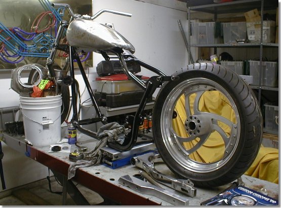
The critical thing is that I’ve got short arms and legs (kind oftroll-like) so whatever we made, it had to have a low center ofgravity. I tried riding Bandit’s Buell, but when I came to a stop, myfeet didn’t touch the ground. So we agreed that the frame had to damn nearscrape gravel. I kind of fancy myself an iconoclast, so I didn’t want tobecome another ad for yuppie motorcycling. Bandit wouldn’t let mepour acid on the thing to give it a lived-in look. If it was going to be a Rat Bike, heproclaimed with bombast, it had to be cool. Well, cool and twobucks might get ya’ a bottle of warm beer. I was determined to make my mark,rat-assed or not.
Bandit suggested that we chop a couple inches out of the frame.
OK, I sez. Bobbed fenders? Bob’s yer uncle, I sez. Narrow the fender railspace? Narrow it is, sez me. Now we’re rockin’. But to tell ya thetruth, it’s still a frame sittin’ in mid-air and a box full of used parts.
But don’t count us out yet. We’ve got a sizzling summer approaching,I’m outta work (I ain’t teachin’ summer school), the Jack Daniels is flowin’,and we’re fillin’ up more cardboard boxes. Bandit’s a tolerant guy, he’s gotthe summer (if he don’t go sailin’ off to the seven seas), and me? I got abrain bubblin’ like a pot o’ hot chili. No tellin’ where thiscrazy-assed bikeis gonna’ take us.
We threw the potentially radical chopper that Bandit and I have banged together up to this point, into the back of my pickup and jammed over to see the Doctor. Dr. John, the frame doctor took one look at the bike in the back of my truck and shook his head. Behind that scraggly beard and those beady blue eyes there is a wealth of experience. He’s seen a lot of biker hopes and dreams, sometimes nightmares, come through his Anaheim Hills shop. He’s managed to salvage most of them. His wry humor snuck through that tangle of beard, “Hmmm, that’s one nice looking Rev-Tech engine.” Bandit ground his jaw, I fidgeted, kicking at the asphalt.
He looked at our hopeful faces and didn’t want to disappoint, “Ok, I’ll take the challenge, but it’s going to take me a couple of days to figure out how the hell I’m going to hammer this thing into shape.” Bandit and I smiled, knowing that the Dr. was going to save our scrap-iron baby.
The whole idea was to shrink the Pro-Street frame around the engine, with just a slight additional rake to the front end. I’m 5’8″ but with short arms and legs, so we wanted the bike frame to be custom fit to my body- frame proportions. We had been looking at some of the bike designs from Japan (where the guys are built more like me) for inspiration.
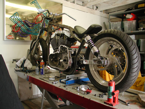
Just with the modifications that Bandit and I have done so far gives some hint as to the unique feel of this design. With the massive Rev-Tech 88-inch engine and 6-speed Revtech transmission squeezed into place, it looks like a Star Wars space sled. I kind of like the rusty, unpainted Pro-Street frame. It gives it an elegant rat-bike look. But then that’s just my twisted sense of humor.
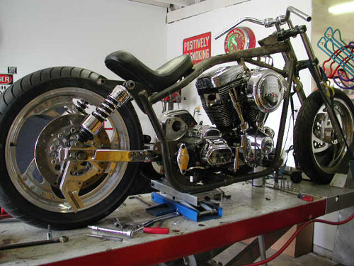
With the rubber-mount engine we have to leave some room for wiggle, so the frame can’t fit like Saran-Wrap. Cutting an inch or so off the swing arm will bring the back tire teasingly close to the inside-front of the swing arm. With a tiny back fender and stretched our front, the ass-end of the bike will look like it’s tucked in below the seat. I said it’s going to look like a running, weird-assed wild hyena. Bandit didn’t care for the comparison and shook his head discustedly.
When we built the Blue Flame, the whole bike was engineered to fit Bandit’s stretched-out body dimensions. Not every bike rider is built like that gangly orangutan, Bandit. So we’ve put a lot of thought into the design of this bike, in terms of scale and proportion. Even the choice and location of foot pegs, shifter, brake pedal, style of handle-bars, and primary shield, will reflect these concerns.
While the doctor is bending and welding the frame into shape, we will be working on paint design, tank and fender design, and ways to clean up some of the wiring, break lines and cables. Or maybe we’ll just fuck off until the doctor calls. Hey, it’s summer and we need to mellow out some.
The day started moderately okay. Bandit and I were going to zoom up toIrwindale to talk to Geoff Arnold at his Joker Machine headquarters to order a raft of parts for the Shrunken FXR, then toAnaheim Hills to meet John the Frame Doctor to check out the progress on myframe, we thought we might also catch lunch with Scooter, our notorious Bikernet criminal attorney, then a leisurelyglide back to San Pedro. No sweat, you say?
The closer we got to the foothills, the morning mist mixed with thecarbon monoxide of a million or so cars careening all over the L. A. basin.Ocean breezes pushed this toxic stew into the eastern edge of the foothills.By the time we got to Irwindale, the Bandit and I were like a couple ofbreakfast eggs sizzling in a skillet.
Bandit called the Doctor to confirm our plan to pop by. No way, no how,says the Doctor. He’s having a PMS kind of day. He hasn’t started on mybike. He’s got a hemorrhoid of a project to hammer out before he can starton mine. Dr. John also repairs sportbike frames and reported that sometimes the frames are so mangled that, well they should be shredded, not repaired. He was up against one of those. So no doctor visit.
A call to Scooter gets about the same results. He’s got to work so nolunch. The day was starting to feel cursed and doomed.
So we knock on the door of Joker Machine. On the other side of the doorwe could hear the banshee howling of an animal possessed. As we walked in,Studley the Joker mascot, attacked with teeth bared, an upper lip curled inschizoid disdain. The rabid Chihuahua snarled, yapped, barked and yelped ina psychotic frenzy. Damn near took Bandit’s arm off when he bent down to patthe little demon on the head.
Geoff grappled with the chain, holding back the crazed critter andwelcomed us with a hearty handshake. Geoff was a gracious host, showing usall the latest Joker products and a few of the Joker toys including their new truck.
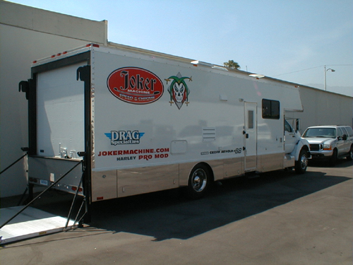
Joker’s new Renegade traveling drag racing garage and party room.
Brian was outside welding together what appeared to be girders for abridge. It turned out to be the sturdy ramp superstructure for the improvedJoker Machine stationary Dyno. Like everything at Joker Machine, expertise andquality construction dominated. That’s one reason we chose to use Joker controls, footpegs and aircleaners and their new rocker covers. The blue flame was domintated with Joker components primarily due to fit and finish. Bandit has never purchased a Joker part and had to modify it to fit.
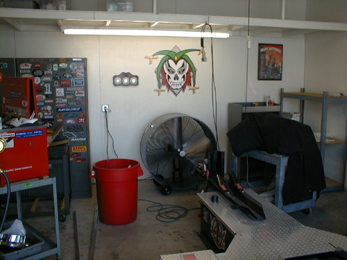
Secret Joker Dyno testing facility. What will they think of next?
Joker is in the process of developing a testing facility for a new line of products, yet to be released to the public.
Over lunch and beers we discussed our design ideas for the new bikesBandit and I are working on. The crew of Joker Machine looked at each othercautiously as Bandit babbled vague musings about “design integrity” and”hidden exhaust systems” or “creating a dense engine compartment.” I chimedin, gesturing with my hands, waving my arms to demonstrate the contours ofthe frame and tank.
Geoff grinned and said that he thought Joker Machine was up to the task.Bandit laughed and said that we had planned to integrate a number of JokerMachine products into our new bikes. Joker Machine, Bandit said, is the bikeparts distributor of choice. For example, he said, products like theadjustable foot pegs allow for adaptation to the individual rider needs.
In addition to the adjustable foot pegs, we intend to integrate into ourdesign with Joker Machine tear drop vents, hand controls and a Joker air cleaner. Weplan to modify Joker Machine forward foot controls to mid-controls.
The Joker Machine crew grudgingly finished their beers and got up toreturn to work. We all walked out side to a blast of heat that would curlthe devils eyelashes. Brian climbed into the back of a Joker truck housing a new V-Rod for product development. Brian recently graduated from advanced schooling in metal fabrication and the Joker crew is looking to him for inspiration and guidance into new product arenas while their CNC design wizard Richard continues to modify and develop new billet products.
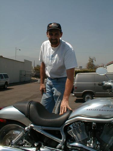
Brian the Joker steel fabricator wizard pondering the V-Rod.
Bandit and I ordered everything from Joker point cover to forward controls that have zero slop, positive lever movement, built in stop light switch and adjustable foot pegs so you don’t vibrate off the pegs. They make all the difference in the world as Bandit attested to on his ride to Sturgis on the Blue Flame. We will doll up the Rev Tech black and chrome 88-inch engine with Joker Rockers that are fully machined from solid billet. The Wedge design enables total serviceability while the motor is in the frame. Bottom section is completely o-ringed. Base is clearanced for larger diameter valve springs and feature a unique modular baffle system for excellent venting characteristics. We’re also using their hand controls because according to Bandit they’re perfect. Our order contained a myriad of the little item also, like small triangular rear turn signals, mirror, gas cap, oil breather, throttle housing, billet clamps and bullet head bolt covers.
Finally we jumped into my truck and headed back tothe ribbon of shimmering hot asphalt of the 210 Freeway. By the time we gotto the 605 Freeway, it was 5:00PM and the Freeways were all at a turgidstandstill, constipated with lumbering gas guzzling, smog spewing cars andtrucks. It was one of those many moments when we wished we had those tight FXRs splitting lanes toward the cool salt air of the coast.
Doctor John promises to have the frame finished for pick-up next week. We’ll report from his Anahiem, Ca location.
If you’re in the Southern California neighborhood, Joker Machine is sponsoring a show at the Grand Opening of the Route 66 Roadhouse and Tavern, June 22 at 1846 E. Huntington Drive, Duarte, California. Call (626) 357-4210 for more information on the shows and Pig Roast.
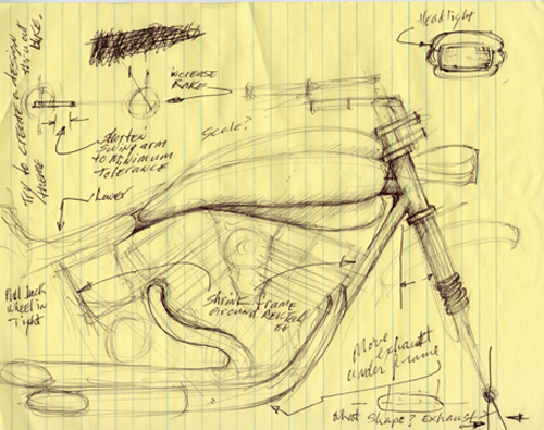
My first concept drawing which Bandit puked on and shit-canned.
Here’s the first of one of my bumbling concept sketches. We will be working with a racing Porsche sheetmetal fabricator on fenders, tanks and exhaust configurations. Wait until you see what Bandit and I come up with next.
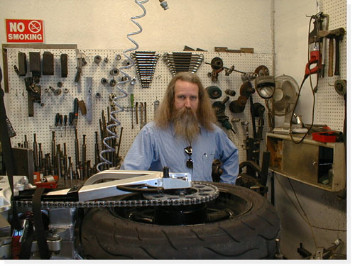
Like the enigmatic fortunes you find inside thosefolded Chinese cookies, our visit with Dr. John–the”frame doctor,” was a mix of New Age mysticism andpractical guidance. The week before, Bandit and Ibrought the rolling Pro-Street frame to the gooddoctor. We gave the him our best ideas of what wethought the bike should become. Basically, we wantedthe bike to fit my body proportions, to shrink theframe around the engine and to still have elements ofa street chopper.
Bandit and I had been trying to create a bike that hada real “signature” identity, yet we weren’t sure whatthat would mean. We tried to convey our concepts withawkward babbling.
Stroking his long, gray beard with a knowing gravity,the doctor calmly listened to our ravings. Eventuallyhe gave us a broad grin through the tangle of beardand said, “Don’t worry, boys, I understand exactlywhat you need.”
We had left the bike with vague misgivings.”Do you think he really has a clue what we want?” Iasked Bandit.
“I dunno,” Bandit said, staring off into the acrid,smog-laden sky.”The guy’s kind of strange, but everyone I’ve talkedto says the guy’s a wizard,” Bandit musedmysteriously.
When we pulled up to Dr. John’s shop, there was ourcreation leaning up against the wall. Not averse tostreet-corner poetry, I intoned, “What a bitchin’fuckin’-lookin’ bike.”
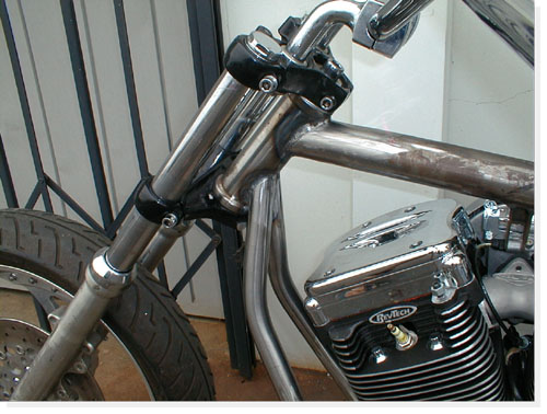
“Man, that bike is really unique,” Bandit exclaimed ina more civilized tone.
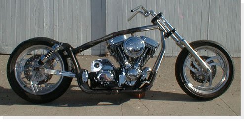
As we oohed and ahhed about the bike, Dr. John camearound the corner, grinning. I jumped onto theseat-less bike and grinned. It fit perfectly, betterthan an O.J. leather glove.
“I really think you’ve got something good goingthere,” the doctor spoke with unconcealedappreciation. “I wasn’t sure it was going to workuntil I got into it. The bike began to speak to me. Ithink it’s got the right karma,” the doctor spoke withmysterious gravity.
All this mystery was not without reason. Dr. Johnstarted this trek to ultimate frame adjustment workingat Goodyear Tires. A fortuitous opportunity, sponsoredby Goodyear, for advanced training at L.A. Trade Techgave him the chance to try motorcycle repair.Recognizing that he was more interested in bikes thantires, he began a course in bike repair withinstructor Pat Owens.
Dr. John soon connected up with a bike shop calledMotorcycle Menders. Right away, he could tell that hehad a better-than-average sense of what was needed tofix most frames. Eventually, he opened his first shopin Covina in 1983. In 1990, he moved to his presentlocation in Anaheim.
Dr. John’s expertise is extended to both traditionalstreet choppers and to the more exotic road racebikes, where competitive tolerances and alignmentshave seconds off of lap times. The challenges to hisexpertise in frame adjustment include the extremes ofcreating a bike for a 6’9″ rider and a Harley with a25″ over stock front end. For his own use, he isbuilding a karma-tingling three-wheeler with a VWengine.
In his shop, amongst a tangle of tweaked Ninjacarcasses, “destruction derby” ATV frames, twistedchopper forks and even a mangled Vespa body, Dr. Johnholds court. Side-tracking his stories about gettinginto the frame adjustment business, he mixes conceptsof metal stresses with ideas of mental stresses,Eastern philosophy, acupuncture points, shakras andauras, martial arts movements, elements of a good dietand muscle alignment of the spine.
The conversation stumbles easily into his personalexperiences. After an injury of his own, he explored avariety of methods of pain control, eventually meetingan American Indian psychic whose exotic beautyhypnotized him as much as her cosmic consciousness.Here, a glint comes to his eyes and a wry smile bringsone corner of his mouth up. “A rare beauty,” hemuses. “An aura just like Cleopatra of ancient Egypt.”
Bandit nodded in agreement repeatedly, like thoseDodger dolls that bobble in the back windows of cars,to the good doctor’s banter. Bandit slurped his greentea while listening to enchanting tales spun by theDoctor. While I shoveled in heaps of steaming andspicy-hot Kung Pao chicken, my eyes teared up and mynose started running.
“The magnetic flow is a flux of energy in the bodyof…” The steaming pots of green tea and plates ofexotic Chinese food sent wisps and tendrils dancing inthe air above our table like a chorus of swaying,sensual nymphets.
“The assorted colors of shakra balance…” Thisadventure had the aura of Zeke the Splooty about it.We were on a cosmic motorcycle Magical Mystery tour.
An hour or so later, Bandit and I were back on the 91Freeway with the bike strapped to the bed of hispickup, staring ahead kind of dumbly. “What a trip,Dr. John is,” I said.
“Yeah, but I think he did a great job on the frame,”Bandit said.
“Yeah, cosmic man,” my head was stuck in the ’60s.”What do we do now?” I asked.
“Let’s check out some trippy paint for the bike,”Bandit smiled. “Let’s drive down to Stanton and see ifWes at Venom can come up with something exotic enoughfor this mystery machine.”
“Go for it,” I laughed.
It’s days like these that make bike building seem likethe right thing to do. Bandit slapped in a tape of’60s funk and we were sailing down the road like acouple of latter-day Kerouac and Keseys.
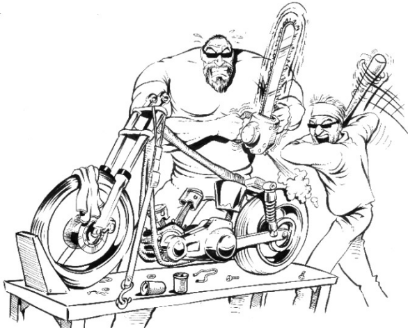

“Hand me a bigger hammer, goddamn it,” Bandit hollered across the garage. We were slamming together as much steel as we could to get this Frankenstein of a bike together in time to show it to the crowds at the Queen Mary Motorcycle Show this weekend.So far this week we’ve managed to cut 1.5 inches off the swing arm. This brings the wheel into the back end of the bike at the point of the pivot. We are designing the bike with brevity in mind. We are hoping that the finished impression will be a bike shrunken around the RevTech 88-inch motor and Rev Tech 6-speed. Oh, we’ll have devilish accents here and there, but the overall concept is lean and mean.
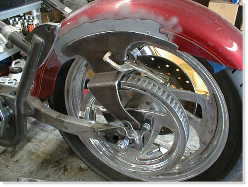
To that end, we are cutting off any unnecessary tabs and struts. Of course, everything changes as soon as a UPS box arrives. Joker Machine parts arrive every couple of days. The foot controls arrived. The new front Avon tire should be here Monday or Tuesday. It arrived, we had it mounted pronto and the fender was looking good. I hauled it to Urs who is a master body man and he widened it to fit perfectly. Having the right tools makes a big damn difference.
A new front tire was called for because the sexy front fender from Cyril Huze was too narrow, since he builds bikes for 19 and 21-inch from wheels and we’re running an 18 (our fault).
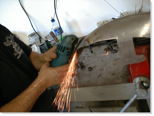
After banging the hell out of the fender to try to squeeze out a fraction of an inch clearance, we decided on a smaller sized tire. We ordered an 18/ 100-90. We hope this will allow us at least 3/8-inch all around.
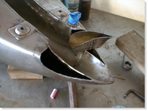
The new Cyril designed stretched tank arrived with the fenders. We cut out part of the bottom of the tank at the back where the front of the seat is, since every goddamn thing we do is backwards. Every builder in the country stretches bikes, we shrink ’em, so the tank won’t fit without mods. This move helped bring the tank down closer to the engine and since the FXR is short, well you get the picture. The tank tabs are in place and welded.
We decided to use an old rear fender off one of Bandit’s past bikes–a Fatboy. We turned it around backwards, the front end will be bolted to the center of the swing arm. Our next problem was how we were going to hold up the stern. After a lot of head scratching, cussing and phone calls we met with master fabricator James Famighetti who suggested that we create our own struts that will be bolted on the inside of the lower rear shock absorber bolt, then welded to the outside of the fender in such a way as to add to the over all look and strength of the fender and conceal the stock aspects. Mounting fenders to swingarms is treacherous. It will vibrate like a dog attacked by killer bees, so it better be strong and still able to remove for touchup.
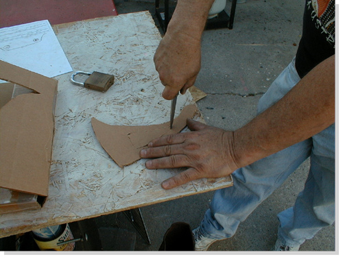
No problem, you say? Ah, ha, not so easy kimosabe! We are pretty sure the strut will have enough clearance for the Rev-Tech brakes on the right side of the rear tire. When you come around to the left side, you’ve got the pully to contend with. So on this strut we added a 2″ dog leg to clear the pulley. I made up the patterns on cardboard and the Fam-Art brothers cut and bent the pieces. Then it was time to fit. We’re getting there.

The BDL pulley from CCI is smaller than the one we used for the mock up. So with our fingers crossed, when all these parts come together this week it will be amazing if they all fit. They did, well, perhaps not perfectly, but we’re getting close.They did, well, perhaps not perfectly, but we’re getting close. If not, “Bandit, get me a bigger hammer, goddamn it!”
Here’s the score. The fender needs tabs and it’s ready. The rear fender needs rivet removal and the massive tabs tack welded. The shock tabs have been cut since the Progressive Suspension shocks from Custom Chrome need to be set wider away from the fender tabs. Let’s see if we can make it to the show. We’re still waiting on Huze oil tank mounting tabs.

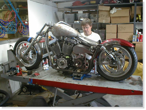
The saga of the Amazing Shrunken FXR continues. This project is notonethat is merely slapping together after-market products to build a facsimileof a customized Harley-Davidson.From the start, Bandit and I sought to create a unique ‘signature’ bike.Even though we have used a lot of after-market products, most have beenmodified to fit our design plan. The products we use, from the FXRPro-Street frame to the Rev-Tech engine to the Joker Machine qualitycomponents, to Cyril Huze, Avon and BDLare some of the finest products available.

Because some of the fundamental elements of design were modified, we havebeen constantly fabricating new brackets, tabs, mounts, and studs. Eachmodification created new issues relating to the fit and function of thedrivetrain. It seems as if we’ve bolted and unbolted the elements of this bike ahundred times.For example, the frame was modified by Dr. John to fit the Rev-Tech engineinto our overall design concept. The top motor mount was bent to fit thenewspacing. We used this motor mount point to position the Cyril Huze teardropgas tank. When we positioned the tank we related it to the handle barclearance at maximum turn position. Rubber mount brackets were welded inplace. The tank was cut at the underside back end to fit low on the frame.It looked hot. Next I cut the La Pere seat pan to hug the pointed rear ofthe gas tank and strengthened the seat back. There is a continuousdouble-‘swoop’from the handle bars to the back of the rear fender. The seat pan lookedhot.
Then we tried to put the engine in. It didn’t look fit. The engine wasmere fractions of an inch from fitting. Even if we could have hammered itinplace the subsequent tight tolerances would surely create problems as thebike rattled and roared down the road.
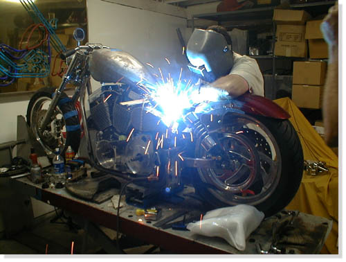
At this point, we cut the original tank brackets and repositioned themodified tank a little higher on the top frame tubing. The tank looked hot,the engine fit, but now the handle bar swing is a fraction of an inch tooclose to the tank. This means we will probably have to have custom handlebars.
It still looks good and we’re still optimistic. Even as wedroppedthe tank down on the new rubber mount brackets and began putting in the5/16″bolts, we found that the right rear bolt was too long to fit. So we got abolt with a thinner head and with my small fingers, I got the bolt in andstarted. We were still looking hot.
We decided to see if the belt fit since Bandit had cut andrewelded the swingarm 1.5 inches shorter for that Amazing Shrunkenlook. Bandit said no, the belt wouldn’t fit. It wasn’t suppose to. Isaid it looked close. As welooked at the bike we realized we’d had to remove the engine, drop thetransmission, which meant we’d have to support the swing arm. It alwaysseems harder than hell to make something easy. So with a couple of scissorsjacks, hunks of wood, and a crow bar, we were able to loosen the rubbermounton the left side of the pivot point of the swing arm. Then we gingerlyslipped the belt in, put the rubber mount back and bolted everything backtogether. Damn! It fit perfect and we were looking hot.
Wait a minute. The right side of the belt was almost touching the edgeofthe back fender. Quick surgery with a saws-all cut a chunk out of thefender. Fender fits, belt don’t rub, bike still looks hot.
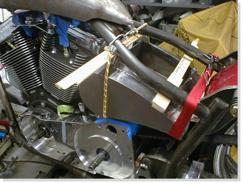
As we cram more operational parts together, the room to move gets lessandless. Next we positioned the oil bag, which also brought up the issue ofthebattery accessibility. With bungee cords, a busted yard stick and some woodshims, we finally got the bag in what seemed a reasonable position. Fourrubber mounted brackets were fabricated then welded into place. It lookedHot. Everything was bolted in place. And everything looked Hot.
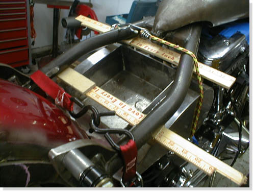
Ah, but not so fast kimosabe. We shaved the fins off the back ofthe oil bag for more clearance. With the two rubbermounts in place atthe rear of the oil bag under the seat pan we had enough clearancefor the battery, in the front for the engine and exhaust, under itfor the starter motor, but no clearance for the ever moving rearfender. It needed at least 1.5 inches of shock play since it’sattached to the swingarm. We had to peel the bag out of the frame andtake it to the Famighetti’s metal fab shop, Fam-Art, for theirexpertise. They came up with a plan to scoop out the back of the bagto the battery box without shortening the overall look of the bag.Then the fender will have the clearance to move with the swingarm andstill look hot.
Next, we neet to investigate whether the Joker controls canbe mounted mid frame. At the same time we will begin fabrication ofthe Amazing exhaust system. It’s gotta be lookin’ hot one way oranother.

Bandit and I were checking out the Amazing Shrunken FXR. “Thedamned thing,” referring to the shrunken FXR project we had beenhammering at, off and on, for almost two years, “has attitude,” hegrowled, “a bad-assed attitude.”
“Yeah, but will it have sound attitude?” I mused. “I want it toget attention. I want it to be felt in their chests before they seeit. I want them to hide their children from the evil they fear.”
The Amazing Shrunken FXR has developed into a mythic ethos. Froma cardboard box full of rejected, beat-up, and cast off parts, thebike has become a sculptured icon, a physical dream, and perhaps awrong turn down a bad dirt road, three miles back.The project began back in the spring of 2001. After a lot of fitsand starts, the Buell Project, the Sturgis Run, the Deer Gut stewadventure, Bandit’s painful recovery, the Red Ball prep, variousevents including a trip around the world and soiree’s, we slappedparts on, hammered steel into shape, welded this and that, cussed andfarted and got to where we are with the help of a RevTech driveline,Custom Chrome, BDL belt, Joker controls, Cyril Huze sheet metal andCompu-Fire electrics. The bike is raw boned, trimmed down, and meanlooking. That’s where it stands, inert and waiting for inspiration,up on the rack at the Bikernet garage.

Bandit regarded the raw metal frame with squinty-eyed intensity.”What you thinkin’,” I asked, keeping my own gaze focused on thepotential of the bike. At my question he stretched out his gangly,egret-like frame to its full 6’5″. “It’ll be a loud mother fuckereither way you play it,” he intoned in his gravitas basso-profundodeep voice. “We’ve shortened the frame and rear wheel base so muchthat it’s barely a cunt-hair from the exhaust port to the rear wheel.”
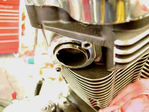
We cut a piece of an Samson Evolution system with a Mikita touse the exhaust port, then started welding other pieces in place. Wecut it back to make a tight turn and create space away from the oiltank.
“Fuck it,” I responded in my best Pancho Sanchezimprovisation, “let’s just start from the port and see what happens.”
We rummaged through a pile of Samson scrap exhaust pipes that wehad scavenged from a dumpster behind the Sampson factory. Flingingout fish tail tips, shot gun systems and swoopy cruiser exhausts,most of them dented and damaged so they couldn’t be re-used. Mr.Samson gave us only the best to modify. We eventually came up withenough pieces to fabricate a Frankenstein exhaust system.
As I grabbed for a section 1 3/4-inch chrome pipe, Imistakenly grabbed a goodly chunk of fur. Bandit’s midget, crazeddemon of a feral cat yeowled in protest and sank his needle-liketeeth into the back of my hand.
“God damn that crazy bastard,” I screamed, “he’s as crazyas a peach orchard boar.” I’m sure Bandit has a mescaline salt-lickfor that freaked out feline.After I extricated my hand from the jaws of Bandit’s feline Cujo, Ireturned to the exhaust system at hand.
Our intent was to minimize the exhaust system as much as possible.We ran the pipe straight down from the front exhaust port, thenturned it to hug the bottom of the engine case. We had originallyhoped to put a flattened pipe under the frame, but reasonable roadclearance dictated a different path. So we tucked it in and aroundthe engine case, then inside the frame, coming out just at the edgeof the back wheel.
“Our first mistake,” Bandit spouted, “we needed a smallerdiameter chunk of exhaust to form guides when welding chunks ofexhaust together. If we had slipped it in one piece even a quarter ofan inch. it would have held each chunk in alignment. That’s onetheory to building pipes. The key to fabing your own pipes is havingenough scrap to slice and dice, then cutting and working each pieceuntil it’s as close to a perfect fit as possible. Finally the tackingprocess is critical. That’s were the guides didn’t come in. If we hadguides we wouldn’t have offset pipes tacked into place. That problememerged severely a week later during the grinding process.”
“It took two days of playing, cutting, fitting and welding toform a completely custom exhaust system in place,” Bandit added.”Make sure you wet towels and form a fire barrior around your tackingarea to protect the rest of the bike. I used a small 0-sized torchtip and common hanger to tack the segments of pipes together. I’m notconfident enough with our new MIG welder with thin sheet metal, so Istuck with the torch.”

” It wasn’t perfect, but it was ours,” Bandit added, “acompletely unique system that would be tucked under the transmissionand attached to the driveline solidly under the tranny backing place.Then we faced the muffler aspect. The pipes were too short to be openor we would have been arrested within a block of the headquarters.”
Needing some kind of ‘standardized’ muffler elements, we went toour local San Pedro Kragen Auto Parts store. With the clamp-on piecein hand, we found parts and pieces enough to create a 7″ mufflercase. “Most of the elements were too heavy and glass packed,” Banditspouted, “We couldn’t weld on a glass pack.”
Back at the garage, with torch in hand, Bandit cut out a sectionof baffles from some scrap Sampson muffler. Spot welding the bafflesinto our jury-rigged muffler, we produced something that may, likeJapanese Fart Wax, diminish the painful ‘Brap-rap-rap’ flutter ofunrestrained exhaust back pressure. A right-angle turn-out willdirect the dragon’s breath exhaust from the screaming 88cc Rev Tech,high-performance engine to an unsuspecting public standingslack-jawed and terrified at the curbed edge of civilization, theirhair-dos blasted straight by the sizzling after-burner of the AmazingShrunken FXR.
“He gets sorta twisted,” Bandit muttered shaking his head.”Actually with the baffle in hand we went to San Pedro Muffler Shopand looked at the myriad of tips and tubing alterations we couldmake. We found a tip and had a chunk of 1 7/8 tubing spread to matchthe tip. That formed the other end of the muffler. We just had toweld the three elements together.”
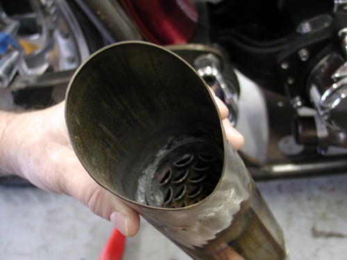
I welded the baffle in place, positioned as it was in theSamson System. I discovered that the two elements didn’t want to weldtogether. I have a feeling the tip was made of an inferior metal.
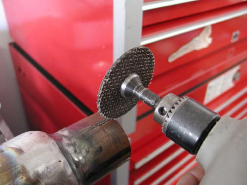
With the die grinder we cut notches for the muffler clamp.
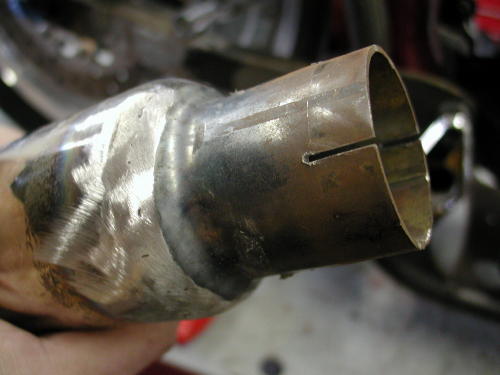
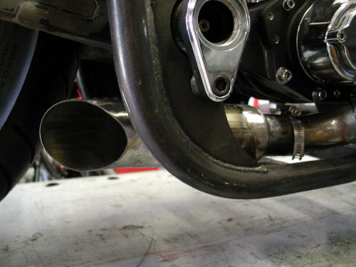
“After welding and fitting I stood back and was proud of ouruniquely tight system that would allow Giggie, from Compu-Fire, tomachine mid-controls for a final touch,” Bandit interupted. Theexhaust played perfectly into the Shrunken aspects of the project. Iremoved the tacked system and began hours of gas welding to make itwhole. That’s when all hell broke loose. While working on anotheraspect of the bike with my back turned to my partner, he began togrind the welds. The college art history professor sought perfectionwith each weld and ground right through the thin walls of the18-guage exhaust pipes. It was amazing. I was sure the system wasruined.”
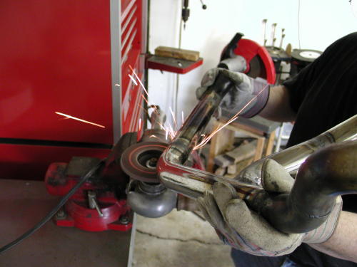
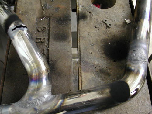
This shows the amount of area ground down so far we were forcedto fill it or destroy the system and start over.
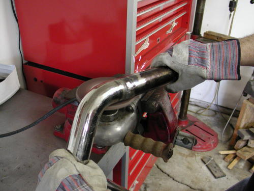
“Some builders tack systems together then take them tomuffler shops for professional construction. I thought that was mynext move. Unfortunately a regular muffler shop doesn’t have themandrels to make the tight bends we had proposed. I was devastated,but the man told me that he could fill the welds with his MIG welder.
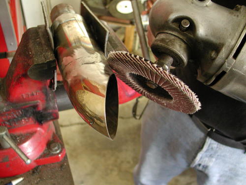
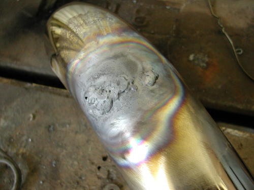
More welds to fill the mad grinder’s cutting work.
“Unfortunately each weld was now a 1/2 inch tall and wide zit atalmost each junction of the pipe. Nuttboy began the grinding processagain. More holes were found and I filled them with gas welding usinghanger rods. I joke now that if the bike runs like shit we blame iton the exhaust system. If it runs well, it’s the same roll of thedice. We’ll see.”
“Making your own exhaust system can be a blast, just don’tget heavey handed with the grinders. Pipe is thin and a little weldthat shows won’t matter much since we didn’t plan on chrome, butblack Jet Hot coating. I’ve sworn off chrome exhaust systems on mybikes for the future.”
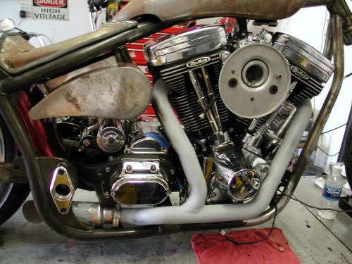
That big bastard just won’t shut up. The next episode in thismechanical adventure will feature Giggy’s attempt a electrifying thesteel monster. Next weekend, barring any new bike projects, Giggy’sinopportune finger damage at the power tools, splattered deer guts,San Pedro political insurrection, Sin Wu’s beguiling charms, a caseof beer, or any other form of diversion or chaos, we will be closerto cranking this monster over.
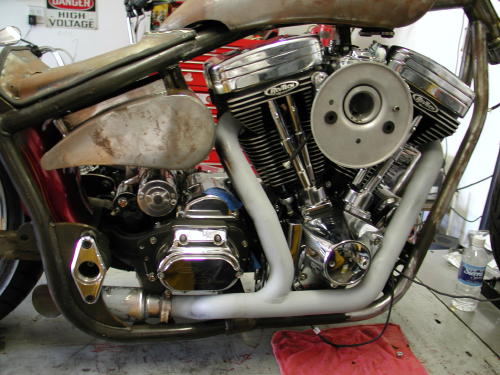
Photos by Bandit and Sin Wu
It’s New Years Eve 2002 and catch up time on the ShrunkenFXR, as if I’ll melt if I don’t cross the line by midnight. And I’mgoing to lower the boom on you. It wasn’t intentional that Giggie,from Compu-Fire, came to the Bikernet Headquarters to help install aCompu-Fire charging, starter and ignition system. He added showing usthe benefits of installing S&S solids in the 88-inch Rev Tech engine.That would seemingly be enough, but since the starter involved theBDL inner primary, Giggie was snagged into helping with the beltdrive installation. That’s not all. As you will see in some of theshots we have Joker Machine forward controls installed, but we’vealways considered mid-controls. Unfortunately for the mastermachinist, we asked for Giggie’s impression and knowledgeablenotions. He dove right in and you’ll see the outcome here. There’seven more, but let’s get started.
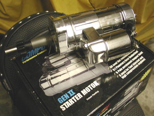
I’ve been running Compu-Fire Electronics for several yearsand will continue to do so. The systems are flawless and a breeze toinstall. I’ve learned to trust their components and enjoy asingle-fire ignition. My discussions with Giggie ran into startingproblems I had encountered before. He pointed out to me that newhydralic systems bleed down as engines cool which closes valves whenyou want that puppy to fire to life once more. That’s where the S&Sportion of this tech began.
Here’s the deal. If the valves are closed while the starter motoris desperately trying to turn over the engine, especially aperformance unit, it’s a bitch. The compression is over the top, andthe electric motor is fighting an up-hill battle. The battery isbeing stressed. This situation is caused when the bike sits and thehydraulic lifters bleed down. Once it fires to life that situation isrelieved.
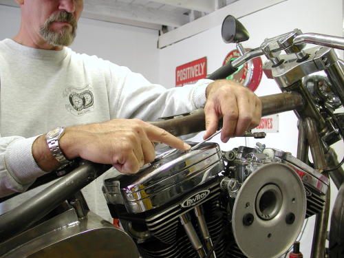
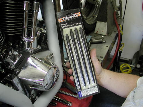
Giggie has been testing and improving starter systems for thelast three years with Compu-Fire. They are developing the mostelectrically efficient systems on the market, but discovered thishitch in the driveline system with the jammed valve train which putsundo pressure on an otherwise fine starter motor and battery. We madea date to install the new Compu-Fire Starter, but in addition, fourlittle rings from S&S would slip into the Rev Tech hydraulics. Sincethis Custom Chrome engine had non-adjustable pushrods we had to ordera set of Rev Tech aluminum adjustable pushrods. We removed the rockercover and arm assemblies to free the pushrods.
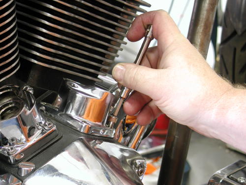
The lifter blocks had to be removed to retrieve the hydraulicslifters.
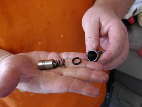
The following shots show the S&S solid ring installationprocess, I hope.
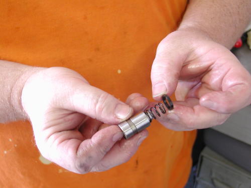
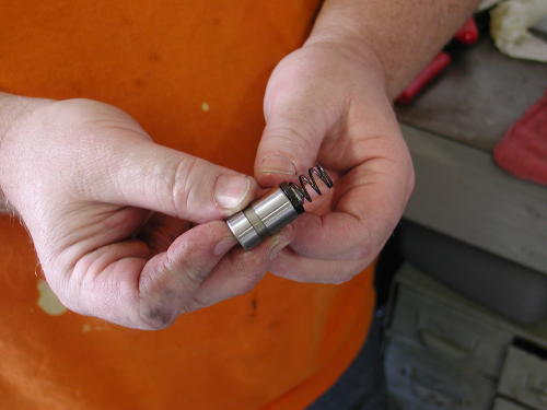
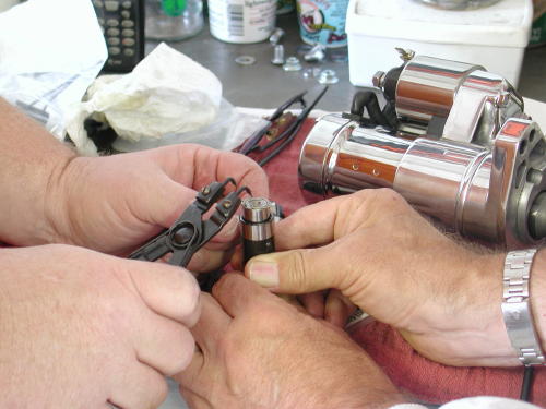
Giggie used snap ring pliers to remove and install the snapring to free the hydraulic piston.
With the lifter blocks removed, the lifter slipped outeasily, and with a snap ring plier tool Giggie removed the ring andthe spring and the piston came free. The S&S ring was slipped overthe hydraulic plunger spring and the rest is history. With the clipring back in place the hydraulics were ready to rock with the new RevTech Pushrods.
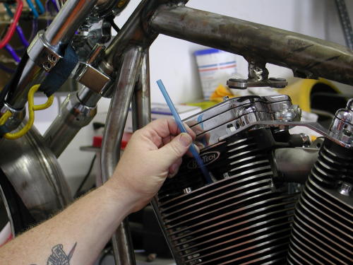
Giggie demonstrated how he adjusts pushrods by finding the intaketop dead center, TDC, position for the front cylinder first. When theintake valve is closing or the pushrod heading down, stick a straw orpencil in the spark plug hole and watch it travel north until it’s atthe top, TDC. check the timing hole for confirmation. Sure enough averticle slot showed up in the hole confirming our position. The camwas also in the perfect position to adjust both the intake andexhaust pushrods for the front cylinder, since both valves are closedfor compression. There is also an exhaust TDC.
The pushrods are adjusted just like old school, solids untilthere’s no up and down slack. You’ll notice that the rings don’t makethe hydralics completely solid but give them .020 slack. Once youhave each pushrod adjusted back off one complete turn. That will giveyou .020 cushion and once the bike runs for the first time you won’thave any tapping like the old scoots had. That’s an easy fix for amajor performance issue. I hate wasting starters or batteries.
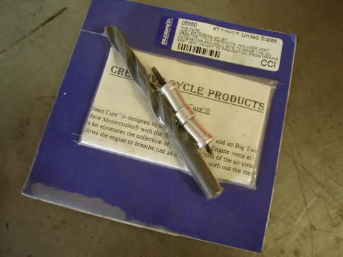
Since we didn’t have the adjustable pushrods on hand we tookthe rocker boxes apart and Giggie pointed out another big inch motorfix. Performance engines that are pushed to redline can build upexcessive oil in the rocker box breathers. That oil will end up inthe air cleaner if it doesn’t have time to filter back through theheads into the oil return line. Creative Cycle Products, distributedby Custom Chrome, designed a fix for this problem. They call this theNose Bleed Cure which was designed to work on all late 1993 and upEvolutions with Nose Breather (engine vents in the heads) system.Installed, the kit eliminates the collection of oil at the bottom ofthe air cleaner assembly. It allows the engine to breath naturallywithout the mess in the air cleaner. The vent extensions, installedin the rocker boxes, allow more time for the oil to filter throughthe head.
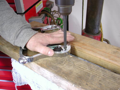
The vent extension is a breeze to install, especially if therocker boxes are removed. The center rocker arm spacer has two areasin the corners for breathers. The inside cavity has a rubbermushroom, Umbrella Valve, poised to limit some air and oil into thearea. That’s the corner we’re concerned with. The extensions wereeasy to install in some respects in the Rev Tech Rocker Boxes andcreated another challenge in other respects. Let’s follow CreativeCycle’s instructions: If we had a battery we would have disconnectedit, first. Since our tank was easy to remove we 86’d it to make roomfor the operation. You could get away with just jacking up the tank.
Remove the front rocker box top plate following the servicemanual. Unbolt the sucker. Then remove the center spacer. Remove thegasket. If the engine is new you don’t need to replace it. Theinstructions also call for replacing the Umbrella valve, but youdon’t need to do that unless it is old and worn or you bury it inaluminum shavings. Umbrella valves generally last a long time, butheat sometimes damages them and they crack. If you are going toinstall the cure in a worn performance engine, replace the UmbrellaValves.
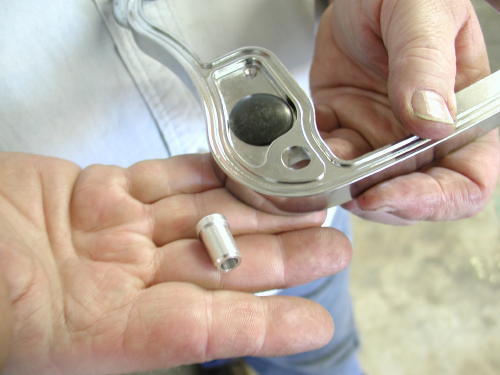
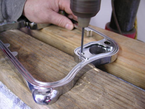
Drill the small drain hole with the supplied 1/8 bit. Using the13/32 drill, bore out the large drain hole. The Rev Tech rocker boxspacer already had a sizeable hole and didn’t need drilling. The ventextension slipped right in. On the opposite side of the spacer thehole was broad and open which didn’t secure the new vent extension atall, which is generally a mild press fit. We cleaned the spacerthoroughly and cemented the extension in place with sillicon on theunderside and let it set up before we re-installed the rocker with afresh gasket (generally the use of silicon on the inside of anyengine is forbidden. But since it’s Nuttboy’s bike, who cares). Makesure the ring is completely clean of any debri or burrs. In mostcases, according to the instructions, the vent extention is a pressfit into the new hole. Tape it gently into place, clean the rockerring thoroughly and re-install that bastard.
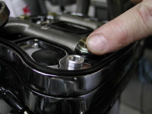
Now perform the same function with the rear head. Accordingto the diagram with the kit, the two breather sections you’re lookingfor are the inboard units closest to the carb. Makes sense. Theoutboard breather cavities are not used. If you are running a monsterengine and want to extend the extension, there are small ringsincluded in the kit to enhance the existing extension although youmay need to clearance the top rocker box cover.
One more time I’ll mention silicone. It’s not to be used in anengine since one little piece could severely block an oil passage anddestroy the engine. The other reason I mentioned it again was broughtto bear by Frank Kaisler and a neatly placed .38 against my righttemple. He whispered angrily in my ear that silicon will not cementitself to chrome. He suggested JB Weld after the chrome was groundaway for a clean sticky porous surface.
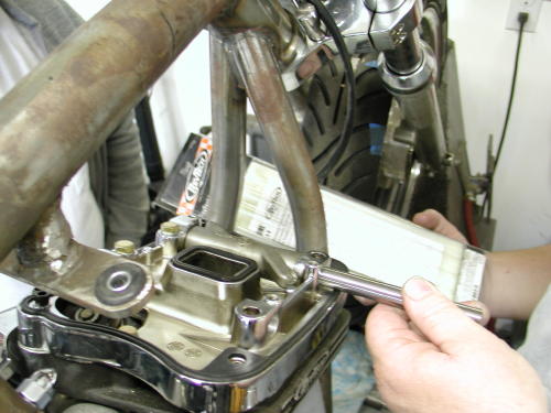
That’s two out of say five techs we need to cover. How thehell are we doing? If you have any questions about this modification,here’s the number for Creative (800) 368- 6217.
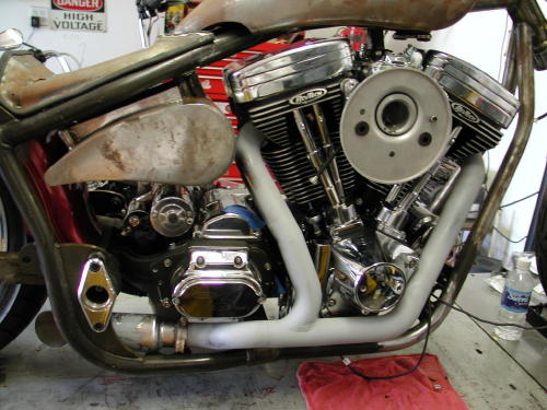
This entire tech process was handled in two differentsessions. During the first we discussed the mid controls notion withGiggie and he altered our course. We were headed in the direction ofstock FXR mid control mounts, that bolt or are welded to the frame.That notion would force us to created large sweeping mounts to clearthe BDL belt drive. Giggie had another notion. Run a shaft throughbushings built into the belt drive inner and outter covers, tolinkage much like stock through primaries, except we would mount thefoot peg on the end of the shaft for the cleanest possible approach.
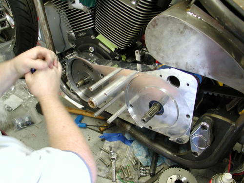
On the right side of the bike we had to make a plate that wrappedaround the tranny cover that would carry a similar shaft that wouldact as the axle for the brake lever. He suggested that we hide themaster cylinder under the tranny close to the rear wheel for a tighthose run to the rear brake caliper. The pipes will wrap around theshaft for the right peg and brake lever. Seemed like a good idea,except for one thought. This is a rubber mount motorcycle and boltingthe pegs to the driveline was asking for foot vibration. We discussedthe concept with several riders and the reactions were varied from”we’re nuts”, to “What the hell”, to the notion that we could run oneset of billet pegs for around town and a vibro-padded set for theroad. We decided to run with Giggie’s concept and try the simplesuckers out.

When we met with Giggie again he demonstrated the outcome.He machined the shaft for the BDL unit and an aluminum guide tubewith brass bushings pressed into the covers. The support unit wasstrong enough to stand on. Next, we needed linkage and a shifter peg,then foot pegs. In this case the foot peg will rotate with theshifter, another odd approach.
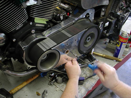
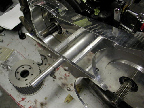
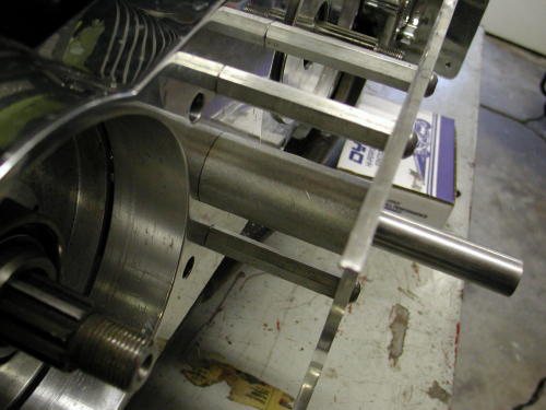
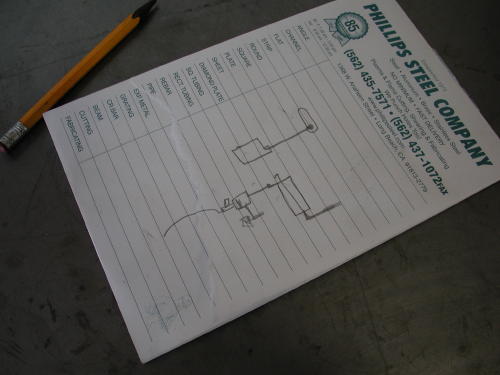
Note the high-dollar precision sketch of right rear brakelinkage mechanism. I don’t get it, do you?
Moving right along we installed the Compu-Fire chargingsystem. This is a breeze, but first you must hit the Harley Shop oryour Custom Chrome Catalog for a set of Stator Torx screws. If you’renot sure which charging system you have here’s a clue: The 32-ampalternator kit is identified by the stator plug protuding from theleft crank case outer surface. The 22-amp stator plug is recessedinto the crank case surface. This particular system is designed tofit all Big Twin models 1981 and later. The rotor may be used withstators rated at 22 amp and 32 amps.
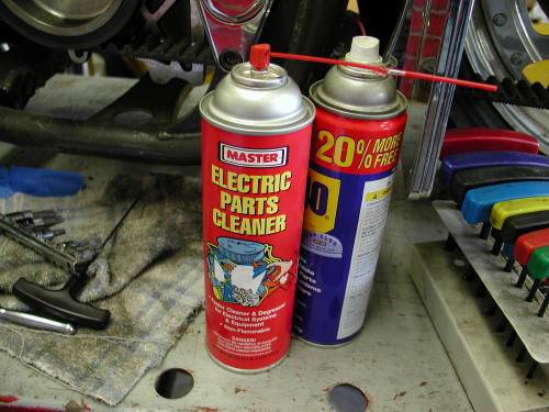
We used the contact cleaner for clearing the stator area ofgrease or debris. The WD-40 was used to let the plug slip into placegently.
We cleaned the area in the left side of the Rev Tech casesthoroughly with contact cleaner. Then we slipped the stator over themain shaft, but not into position. Giggie sprayed the alternator plugwith WD-40 and began to wedge it into the inner slot in the case.First you need to back out the Allen set screw in the case to allowthe plug to slide through. Once the plug is in position (protruding1/4 inch), tighten the Allen set screw with Permatex blue Loctite. Becareful not to over-tighten the screw which could short out thealternator and ruin your day. With the plug in place make sure thewires are safely routed then install and tighten down the stator withthe self Loctite’d Torx screws. Done deal.
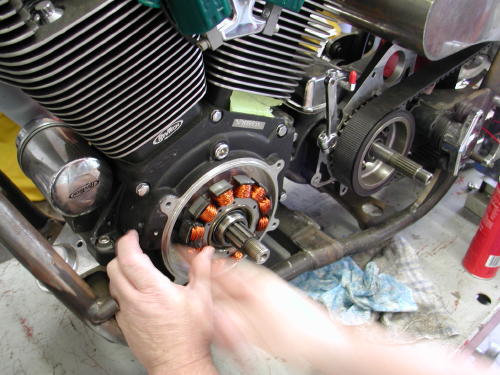
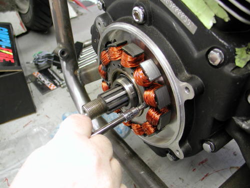
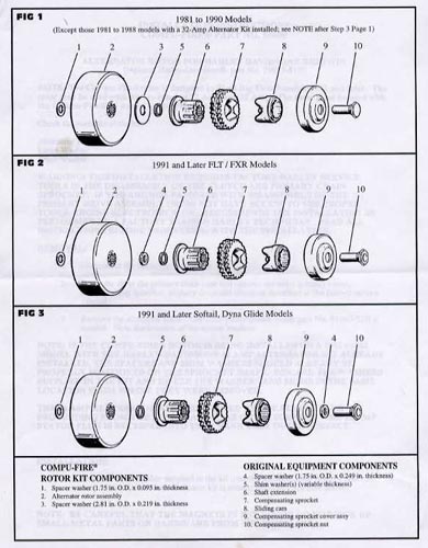
Then Giggie slipped the smaller of the two massive washersover the shaft (except when 32 amp Harley-Davidson alternator kit isalready installed). If the Compu-Fire rotor is being installed on a1981-1988 model with the Harley-Davidson 32-amp alternator kitalready installed, the spacers and shim washers should already beproperly positioned on the sprocket shaft. Discard the washerssupplied in the kit and reuse the washers and shims in the samelocation from where they were removed. Compu-Fire charging systemsare perfect replacements for toasted charging systems.
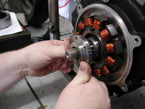
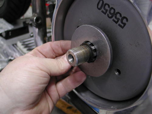
Then he took the BDL engine shaft insert and slipped it onto thesplined sprocket shaft to check the fit. Some sprocket shafts fromJIMS and S&S were slightly different sizes. The splines were machinedto be .001-inch larger across the face. Since the BDL insert fitsnugly, but fit he attempted the same manuever with the Compu-Firerotor. When we installed a rotor on the Redball chopper, we had tofile each tooth to make it fit. That wasn’t the case this time aroundsince Giggie ordered the Compu-Fire rotor with the larger slots orsplines. Note the number on the rotor. The 650 unit is alreadyprepared for the larger shaft, whereas the 600 unit was built forearlier alternator motors. If you need to remove an old rotor you mayneed a JIMS machine tool or a Harley-Davidson puller part no.95960-52B. Be careful that the magnets in the rotor do not pick upsmall metal parts or hardware from the work area before you installit.
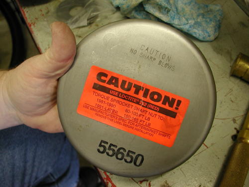
Also note the warning label on the rotor. It says not tosmack the rotor with anything. If you do so severely you could knocka magnet loose, or you could change the polarities on the magnets.Don’t hit it with anything harder that the palms of your hand. Thisone was snug, but slid right into place. Now comes the large flatwasher. This puppy is there for strength. With everyday use the faceof the rotor will flex and can crack. This washer adds strength tothe face and prevents cracking. Don’t forget it.
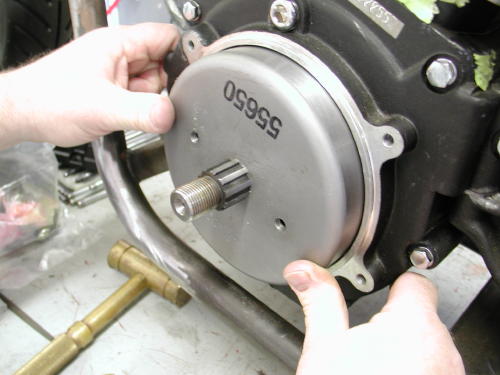
Here’s some notes regarding different models. Thisinformation is supplied with all Compu-Fire charging systems:
To install rotor on 1981 to 1990 Big Twin) except those witha 32 Amp alternator kit installed) place the large washer suppliedand original shim washers over the sprocket shaft (in that order).See figure 1.
To install rotor on 1991 and later FLT/FXR models, discardthe large washer supplied in the kit. Place the original washer andshims over the sprocket shaft (in that order). See figure 2.
To install rotor on 1991 and later Softail and Dyna Glidemodels, discard the large washer supplied in the kit. Place theoriginal shim washer over the sprocket shaft. The original thickspacer washer will be used under the compensating sprocket nut onfinal assembly. See figure 3.
If your are installing this Compu-Fire kit on a stock bike,next you would re-install the primary drive assembly per factoryservice manual and use loctite (red) on the threads of compensatingsprocket nut. The compensating nut must be torqued to the correctspecifications:
1981-1990 models 80-100 foot pounds
1991-Later models 150-165- foot pounds
(for aftermarket shafts use manufacturers specifications.)
Don’t forget to put oil back in the primary.
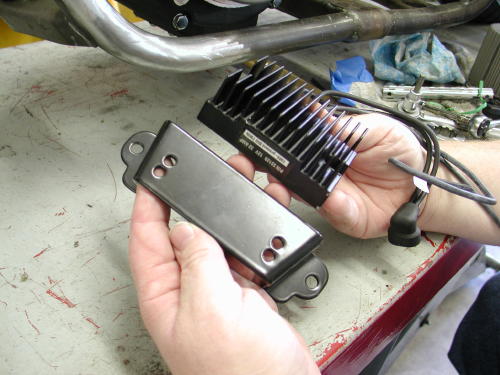
That left the regulator. In the past you would be forced toinsure a proper ground by cleaning some of the regulator case surfaceof paint, the bracket surface and paint off the frame. That’s nolonger the needed. These regulators come with a separate groundstrap, which Giggie recommends that you attach to the engine case onthe right side under the cam cover to hide it. “Make sure the wire iscrimped to a lug, not soldered,” Giggie pointed out, “and that thecase is clean of wrinkle paint before it’s bolted in place.”
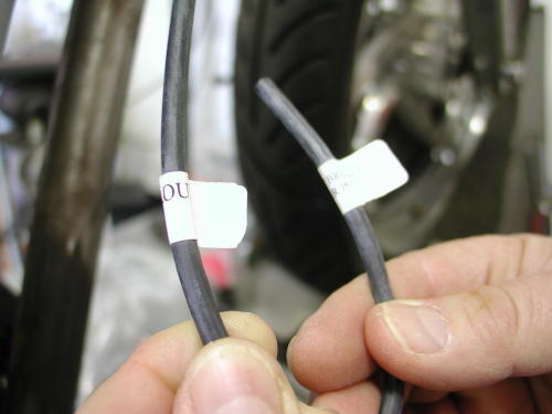
One other wire is afforded with the regulator, the hot wire,which generally runs to a circuit breaker, the battery hot terminalor the ignition switch hot side. There’s a specific reason for notsoldering lugs or connectors, but crimping them. According to Giggiesoldering induces heat to the wires and a completely solid lead bondthat creeps under the wire insulation. The combination creates abrittle point in the wires that can deteriorate and crack withvibration. Wire connectors do not come with the regulator kit. Youneed to find the appropriate size for your application.
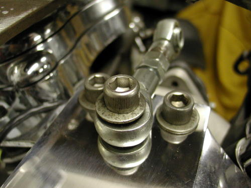
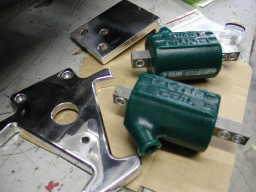
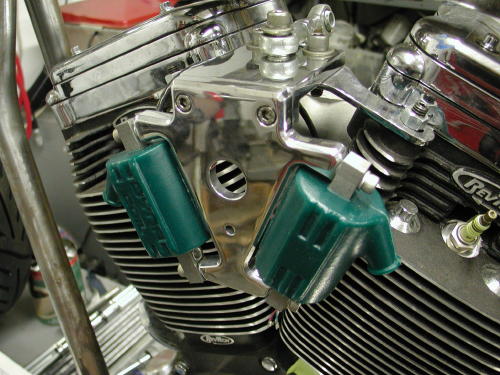
While Giggie was tinkering in the Compu-Fire machine shop,building prototype components for their line of products and slippingin a Shrunken FXR parts, in his free time, we installed 3 ohm Dynacoils required for the single-fire Compu-Fire ignition system. Theyare available from Custom Chrome in 6 and 12-volt models, with singleor dual towers and in 1.5, 3.0 and 5.0 ohm configurations. We chose astrong billet German made bracket, from Custom Chrome, to hold thecoils between the heads. This is one of the cleanest ways to run theelectrics with all the elements close together. The coil bracket fromCustom Chrome was also capable of holding the ignition switch and ahorn button or toggle high/low beam switch. That would be the extentof the wiring for this bike and it would all be tucked under the gastank and between the heads cleanly.
We have also ordered a CCI ignition switch discovered from thewater-craft industry by Bob McKay. It works like automotive ignitionswitch with a key and acts as the starter button eliminating the needfor a starter relay.
What should we handle next, the ignition system or the BDLBelt Drive? Your call? The BDL Belt, okay, here goes. Actually theseunits are increasingly easy to install. Late model bikes with rubbermounted drive lines are in solid alignment which makes these unitslip right into place. Just in case you are working with a pre-unitmodel I will list some alignment recommendations from Frank Kaisler.
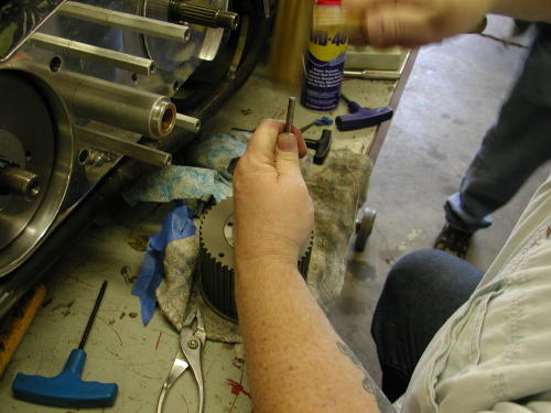
This particular BDL installation came with their brand new SuperStreet Clutch which consists of nine fibers and 11 steels. Installtwo steels first then alternate fiber and steel ending with a steelbehind the pressure plate. Install anywhere from four to nine springsand bolts depending on how much spring pressure is needed for yourapplication.
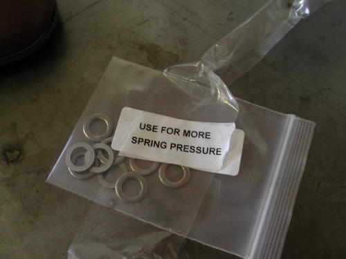
“With this much clutch surface, not much spring pressure will beneeded for proper engagement,” Said Bob from BDL. For additionalspring pressure for monster engine and abusive clutch throwers theyincluded washers to enhance the clutch pressure.
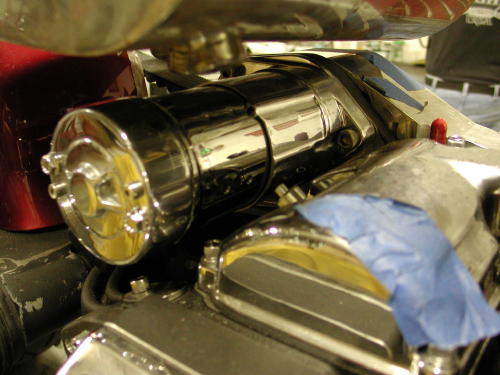
Basically Giggie installed the backing plate first using thefasteners supplied by BDL. Installation on 1986-89 models require theuse of a 1990-up starter and modification to the starter mountinghole on transmission will be necessary. You must open the mountinghole to 2-1/8 inches.
Remove the stock starter pinion gear and complete starter gearassembly from starter. Bolt starter into back side of motor plate.
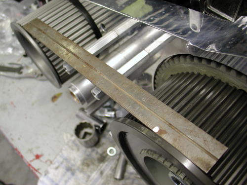
Install the front and rear pulleys and check for proper fit. Atthis time you should determine if the front pulley will need shimmingor not depending on how the pulleys align with each other. Removepulleys and add shims if necessary.
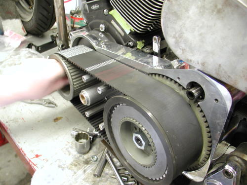
Re-install belt drive placing front pulley, rear pulley and belton at the same time or you’ll discover it’s tough going. Install andtighten to H-D specifications, mainshaft hub nut. BDL supplied aspecial hub nut with seal for all spline shaft models 1990 and later.Engine shaft splines should not protrude from the pulley. Be sure tored Permatex Loctite front engine nut and torque to H-Dspecifications (an electric impact driver is used but notrecommended). JIMS and CCI carry a tool that will lock the pulleys soyou can use a torque wrench. For 1986-89 taper shaft models you mustuse the stock hub nut and seal kit (included).
For spline mainshaft models, 1990-up, apply red Permatex Loctiteonto the back of the BDL hub 1/4-inch inside of the spline and letthe Loctite flow onto the mainshaft when sliding the rear basketassembly on. This procedure is necessary so that the hub andmainshaft will fit together properly and will not let the mainshaftspin inside of the BDL hub. This procedure is not necessary on tapershaft models 1986-89.
(The belt drive was designed with the use of stock H-D frames.The shaft to shaft dimensions on a stock Softail are 12.825 and on anFXR is is 11.325. The number of teeth on the pulleys and the numberof teeth on the belt were engineered to exact fit using the abovedimensions. If aftermarket frames, engines or transmissions are usedthen these dimensions may very slightly. You may need to address thisproblem so that the kit will fit properly. We will not be able tohelp you with this problem, this is an issue to be addressed by themanufacturer of the aftermarket parts that you may be using.)
Rotate the motor (take the plugs out) using a socket wrench, thebelt should track straight and away from the motor plate, but not sothat it may come in contact with the outside pulley flanges. Be surethat the belt drive is not making contact with the motor plate.
Grease the starter shaft and install the BDL starter pinion gearonto the starter shaft, apply red Permatex Loctite to the starterbolt and tighten to H-D specifications (they supply two starter boltswith the kit, one is a 1/4-20 by 2.5 inches for 1990-93 starters, theother is a 10-32 by 2.5 inch for 1994 and up starters. Be sure not totighten starter bolts too tight as this may interfere with properengagement to the clutch ring gear.)
Install the clutch pack, refer to schematic spline steel first,1/2 sided friction plate with fiber facing out, then alternate steeland two sided fiber plates ending with the other 1/2 sided frictionplate with the fiber facing in. This is for the regular clutch andnot the Super Street Clutch which was covered above. Install pressureplate, springs and shoulder blots.To install shoulder bolts apply redPermatex Loctite to a bolt and run in one turn, go onto the next boltuntil all the bolts are in place, then tighten them all the way downuntil they bottom out. There is no adjustment to the spring pressure,this is all pre-determined with the length of the shoulder bolt andexact dimensions of our pressure plate.
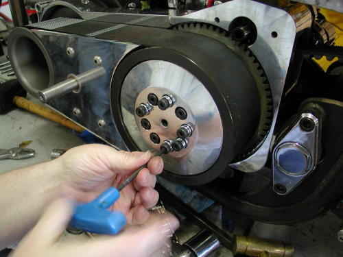
Install the four hexagon cover plate extensions into motor plateand mount side guard with the four button head allen blots.

Clutch screw adjustment should be 3/4 to 1 turn loose from lightlyseated. Note: When the clutch is hot the adjustment screw should notbe seated. Tighten rod nut when adjustment is complete. BDL suppliesa clutch adjusting rod and nut for all models 1990 and up, only.

If your bike is perfectly level, if you put a level on thisruler, it should be level.
SIDEBAR; ALIGNMENT CHECKS FOR RIGID MOUNT DRIVE LINESWith the engine in place and all the lower engine mounting boltsinstalled but loose, take a straight edge and place it on the innerprimary mounting surface of the engine. Look at the straight edge toinsure that the sprocket is parallel to the straight edge, if not trymoving the engine around until the straight edge and sprocket areparallel.
Once this is done snug the rear engine mounting bolts. Now checkthe engines front mounts to the frame with a feeler gauge, if thereis a gap between the engine and frame make some shims to fill thegap. The shims should be a plug fit. A plug fit is the same as a slipfit, the exact shim height to fill the space between engine and frame.
Position the transmission on the trans plate and install in theframe. Place all plate mounting hardware in their respective holes,but leave them loose.
Place the BDL engine plate on the engine and the transmission andinstall all of the mounting hardware. Tighten the plate to enginemounting bolts first, then the plate to transmission bolts. Usingyour hand turn the mainshaft of the transmission to feel forresistance, this is how you will check your work.
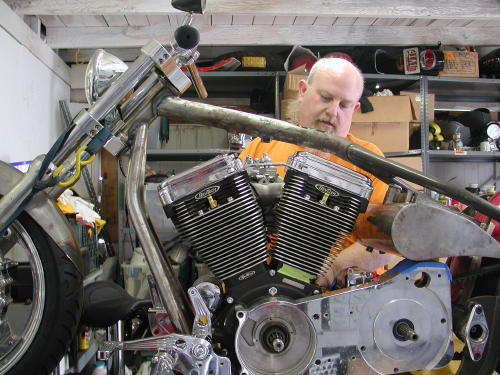
This shows the primary before installing the pulley and the masterCompu-Fire designer/machinist Giggie.
As of right now, you have assured the engine’s sprocket shaft andthe transmission main shaft are parallel to each other. Now tightenthe transmission mounting plate to the bottom of the transmissioncase. Check that all of the trans plate mounting bolts still movefreely up and down, if they or only one of them don’t move freelyfind out why and fix before moving on. Sometimes this occurs due tomanufacturing tolerances. Sometimes just running a 3/8-inch drill bitthrough the frame and mounting plate will fix small misalignments.
Here is where the difference is made. It is a lot easier to shimthe transmission mounting plate to the frame mounts than thetransmission to the mounting plate. To do this take a set of feelergauges and measure the gap at each trans plate mounting bolt, thenmake-up a shim to “plug-fit” the distance. With all four corners ofthe trans plate done check the “fifth” trans mount and shim as needed.
The moment of truth. Start tightening the transmission mountingplate bolts one at a time. Check the transmission main shaft byturning it in your hand before and after tightening each bolt. If youfeel increased resistance after a bolt is tightened then you willneed to go back and check that you got the correct shim thickness forthat one mounting bolt. Keep checking the mainshaft and proceed tothe rest of the mounting bolts. After all the mounting bolts aretight and the mainshaft spins as it should, you’re done.
A good way to double check your work is once everything is tight,remove the engine plate. The engine plate should not pop or springwhen the mounting bolts are removed, and likewise the plate should goright back on and seat against the engine and trans with no effort.
Ok, where to get shim stock. There are a number of machine toolcatalogs that sell a selection of shim stock for about $20-$30. Theseselections come with different thickness sheets of stock that you cutto whatever shape you need. Another source of shims is PerformanceMachine and Custom Chrome. Both companies sell brake calipers thatsometimes need to be shimmed to their mounts to center the caliperover the disc rotor. The mounting bolts for these calipers are3/8-inch diameter, the same size as your transmission mounting platehardware, I have bought a couple packs of these shims to use. If Iremember right they were only a few bucks per pack. If for somereason you have a big gap between the plate and frame you may be ableto use a 3/8-inch flat washer. Most flat washers these days measureout between .060-.068-inch in thickness, you may still have to addanother shim to achieve the plug fit you are looking for. Anothersource of shim stock is beer or coke cans, if I remember correctlythese cans measure out at around .014-inch, but it has been a longtime since I measured one.

The main thing to remember, is that the mainshaft must always turn free,maintaining its parallel course with the engines sprocket shaft.
When speaking of parallel shafts, that’s plural parallels.Both planes, vertical and horizontal. Believe it or not, careful set-up ofthe belt drive, or chain drive frees-up hidden horsepower.
When both shafts turn parallel, true parallel, requires the least amount ofpower to turn. Freeing that extra few ponies to do your bidding, not tomention better fuel mileage.
–Frank Kaisler
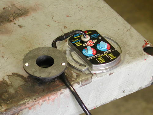
Compu-Fire Ignition model 21835 installation–the last hurtle.For kickstart you need the 21835KS. The electric-start unit delaysspark for two revolution to allow the starter to get rolling.
We are finally to the bottom line, the last straw, the final beerin the six-pack. We face only the simple, yet precise Compu-Fireignition system. I’ll try to make it quick.

First find front cylinder top dead center TDC as we describedbefore with the straw (won’t hurt anything) in the sparkplug hole,after the intake valve begins to close. The notch on the cam shaftwill be at 7:00 at TDC and you know that you’re cool. There shouldalso be a straight verticle line in the timing hole, anotherconfirmation.
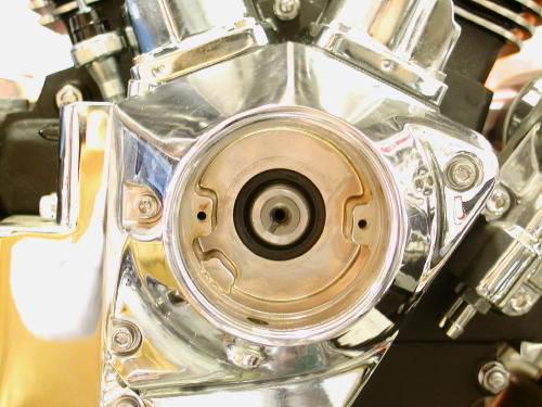
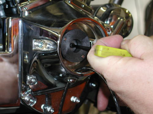
First you need to remove any previous ignition systemright down to the cam shaft. Now bolt in the Compu-Fire ignitionrotor or trigger wheel with some blue Loctite. Giggie then bolted inthe Compu-Fire ignition plate and turned in counter clockwise. Afteryou run the wire loom out the bottom of the Rev Tech cone. Dig out a12-volt battery and hook the red wire to the positive terminal.
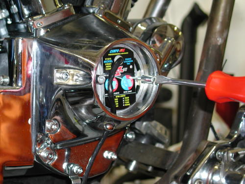
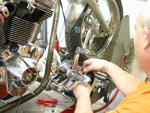
Tape off the black, white and green wires so they don’t ground orshort to the battery. Power the red wire up with a ground link to thebike. The LED light on the Compu-Fire plate will alight.
Grab the magnet that comes with the kit and hold it with theHarley orange dot away from the plate and swipe the magnet left toright along the bottom of the plate. The light should go out, if not,turn the magnet over and try again. Slowly turn the plate clockwiseuntil the exact moment the light goes on again. You’re timed, donedeal, simple. You’ve static timed the bike in its advanced position.Lock the plate down and disconnect the battery.
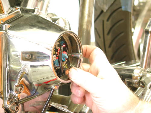
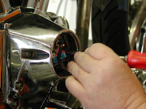
You wire this with with the red wire heading to heignition switch. It’s the hot wire. The Black wired hauls ass to thefront coil, the white wire to the rear coil and the green to the VOESswitch. That’s the single-fire set up. For Dual fire aim the blackwire to the coil and tape off the white wire. The green is guided tothe VOES advance switch once more. Giggie likes the VOES switch andI’ll try to explain why. I would prefer to throw it in the trash, butnooo. We will install the VOES switch in the wiring tech, later.
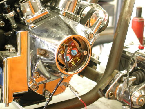
I like the concept of single fire for a smoother running engineand separate coils for each cylinder for a stronger spark. Some maysay, “Bullshit.” But that’s my notion of single-fire ignitions. Thisunit has two switches, let’s start with the left. You turn it to dualor single-fire and it has eight advance curves. One to three are setfor 35 degrees BTDC advance. Four to six are 32 degrees of totaltiming, seven is 30 degrees and eight is 28. There are threedifferent curves bringing the engine to total advance at differentRPMs, one is 1,500, 2 at 2,000 and three at 2,500, based on themotor. We set it at six because I’ll be running the VOES.
The right switch controls the VOES. You can have it set at50 percent or 100 percent. Fifty percent is advanced 5 degrees and100 percent, 10 degrees. It adds timing at necessary times but willnever add timing over the advanced maximum. The final setting on theright is the Rev Limiter. The best use of the rev limiter is to setit 500 rpms past peak power. That means some testing is needed to useit effectively. No problem. It’s designed to prevent over revving themotor because of a missed shift. The right hand switch controls theVOES and the rev limiter.That’s it goddamnit. I can’t believe I made it to the end. Wejust hauled the Amazing Shrunken FXR to our master metal fabricator,James Famaghetti for final craftsmanship. We need to install aSportster kickstand kit from Custom Chrome and Giggie’s controls,then it’s the three “P”s, paint, powder and plating and this puppywill rock. Hang on. We’ll be back in a couple of weeks.–Bandit
You’ve been there. You handed the Makita cordless drill toyou’re drunken buddy, and he drilled a hole in your big screentelevision. You tried to wrap the extension cord around his neck andfinish him off. We came close to blows in the garage a couple ofmonths back. I spent days carefully welding chunks of Samson exhaustpipes together to form a one-of-a-kind exhaust system.
All the welds were performed with gas and hanger rod. Thepipes weren’t perfect, but they fit the bill. They were actuallyintended to be prototypes, to be duplicated by a paid professional.After the first pass was completed the pipes fit like a glove,although they were artistically rough around the edges. Nuttboy cameby on his Wednesday afternoon escape, and I handed him a highspeedgrinder and instructed him to round off the welds. I worked onanother project and paid no attention while sparks flew. When he wasfinished he tapped me on the shoulder and said humbly, “Not sure thisis what you had in mind.”
He had ground right through the pipes and left gapingholes alongside most of the welds. In addition, I discovered to myteeth-grinding dismay, that there were still large sections of thepipe ground so thin, that as soon as the torch tip came within 6inches of the surface the pipe melted away. I spent another whole dayfilling the gaps. Who knows what will happen when the struggling bikefires to life. We’ll have the only exhaust system on earth withbaffles throughout.
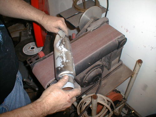
That’s not all. The grief continued. I hand made a mufflerusing a portion of a Samson baffle. We purchased a chromed, truckfender tip from San Pedro Muffler and went to work, but after hoursof screwing with the shiny metal we almost shitcanned the unit. Thefender tip was made out of a strange metal, almost pot metal, thatdidn’t seem to take to the gas welding and wouldn’t respond tobrazing. For every hole I filled, another crack lurked. I welded,then smoothed on a bench grinder only to find cracks and holes tofill again. The shorty muffler probably weighs 50 pounds due to thevast layers of welding rod. As it stands, this is a pure prototypeexhaust system. We should use it for testing then shitcan the rankpiece of shit and start over.

Click to order Catalog!
Frustrated, but pleased with the overall look we were readyfor final metal work. This bike is being built by inexperiencedhands, not professionals, in our backyard garage. Sure, I’ve builtsome bikes, but I wouldn’t consider myself a metal fabricator. I cameup with the initial design and we roughed out elements, but we neededa master metal worker to finish what we started. There are preciousfew, true metal craftsman, who I know. One is Billy Westbrook,another is Jesse James and recently, in the news, we displayed metalwork by Roger at Goldammer (Goldammer Cycle Works Ltd.,www.goldammercycle.com ,1-250-764-8002). High quality workmanship.
They’re out there but not on every corner. I stumbledonto another super-slag artist under my nose. James and LarryFamighetti are Hamsters and own a corrugated steel metal shop inHarbor City, California, called Fam-Art. You’d be tweaked to rumbledown Narbonne Street and stumble across this rusting corner buildingthat’s got to be the oldest swaying dump on the block. Theyspecialize in structural steel (you could never tell it from theircreaking tin shed) for homes and buildings. Large chunks of steel,massive shredders, presses and welders are scattered around the funkylocation that’s reminiscent of the first shack Harleys were built in.

Nuttboy and I darkened their doors a couple of times toask them to flame-cut a couple of chunks of steel for our fenderbrackets. The more I hung around the more quiet-James began to showme steel components he had fashioned for some of the local riders. Herebuilt and reformed Harley taillights to eliminate all the edges andgrooves, then welded them to fenders so that ultimately there were noseams. The more I gawked at the sculptured parts, that demonstratedhis ability, the more I knew we had discovered a man capable of BillyWestbrook fabrication qualities. We hauled the entire FXR to Jamesthe next week.
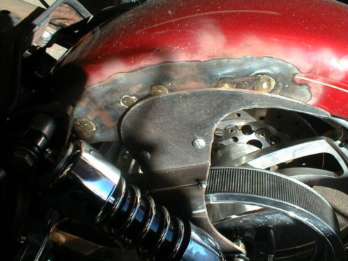
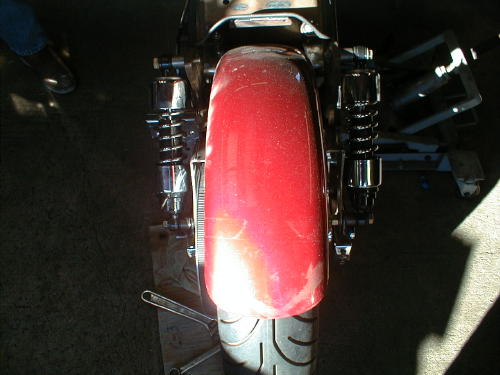
James relocated the straps in such a way to narrow the shockplacement keeping that shrunken look in mind.
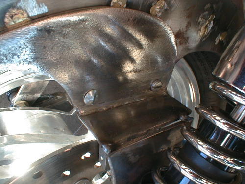
This is a close-up of the right fender strap. It’s beencorrected, reformed and readied for final welds.
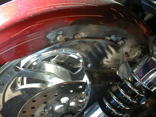

We cut and fitted the tank and made the mounts, butJames filled the underside, rear section for a perfect fit.
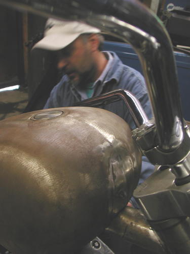
We jacked up the front of the tank and mounted it, butJames filled it and formed the front of the tank to match the customridge along the top. He even made paint work suggestions that I foundinteresting. “If you paint a ridge like this with a light color,”James said, “The ridge will disappear.”
We decided to paint the bike a light House of Kolors pearland create a dark teardrop panel on the top of the tank. He alsocreated and welded fork stops to the neck.
As we rolled out of the shop that day James still hadfinal welds to complete. He straightened out our seat pan, but neededto figure out a mounting arrangement. Finally we needed the CyrilHuze front fender brackets checked and welded into place.
We should have the Shrunken FXR back in our clutches inthe next couple of weeks. We need to finish our rear brake andshifting mechanisms with Giggie from Compu-Fire, fire it up for atest ride and tear it down for paint.
Oh, I need to untie Nuttboy. I need that extension cord.
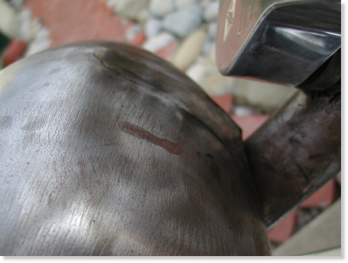
The Shrunken FXR returned recently from Fam Art, in HarborCity, California (310-326-2141). They welded, shaved, mounted theseat, manufactured fork stops and saved our poor- construction asses.James Famighetti mounted our Cyril Huze front fender, welded andformed the tabs and informed us that the Avon Venom was too large forthe narrow glide front end. It was our turn to work on it.
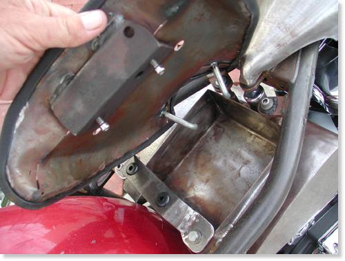
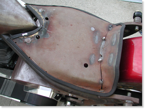
Note that James mounted the seat pan so that the edges wouldnot touch the frame paint in the future.
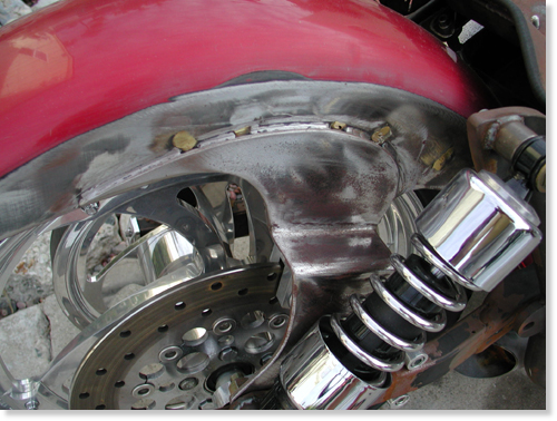
Like any self-respecting bikers we hate to have a bike, oreven components out of our mistrusting mitts. We had another dilemmathat needed handling. The bike still didn’t have a kick stand, and weused two 2 by 4’s, to hold it upright, when not perched on the lift.There’s a trick to this maneuver. If I backed the Pro Street FXR outof the garage and wasn’t hauling the wood planks, I was screwed. Ifalone, I could stand there for hours waiting for someone to strollpast carrying two 2 by 4s–unlikely. After a couple of unsteadyoccurrences, the bike didn’t move without the wood chips on the seat.You can imaging the major pain in the ass this caused.

We ordered a weld-on, Sportster style, kick stand fromCCI, and it arrived complete, with all chromed hardware and thebracket to be welded on the frame. There was one problem indetermining the position. The front Avon was a 100/100 18-inch, andwe planned to replace it with a 90/90. We needed to have the finishedPerformance Machine wheel in place.
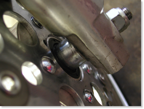
The Avon Road Runner tire arrived, and we had it installed at thelocal Yamaha dealer. James pointed out to us that our front tirespacing wasn’t perfect so I sliced a spacer to give us about a1/4-inch spacer on the right side of the wheel and about a 3/4 inchspacer on the left. The tire, almost centered, now had clearance, andthe wheel floated effortlessly under the modified Cyril Huze frontfender.
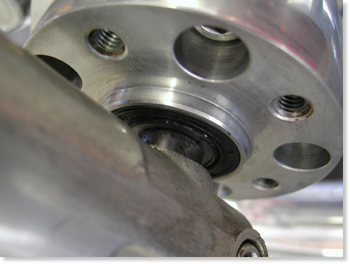
Now we were cleared to install the Hot Match weld-on kickstand.This is a tricky assembly process. First, you need to be absolutelysure you don’t plan to change the front wheel, to a 21, or extend thefront forks. If you do, the kickstand will need to be bent ormodified to fit. It’s not the end of the world, but it will destroythe chrome.
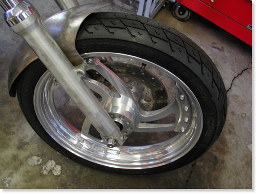
The other trick is determining the right position. Here’swhat my feeble brain told me, since the directions with the Hot Matchdidn’t cover positioning, except to recommend that you take yourtime–no shit. First I stood my Road King straight up and lifted theside stand until it was locked in place. Then I measured from thepoint that would touch the pavement to the ground. It varied fromaround 2.5 inches to 3 inches. I noted that the Hot Match lever wasnearly 3 inches shorter from the point of contact to the center ofthe pivot point. I took that into consideration. I also noted that Ihad lowered my King with shorter shocks, then added a larger Avontyre (a 150). Ground clearance was also a consideration.

Then we picked a placement area on the frame. Our designcalled for little or no forward controls. I kept the tab under theBDL belt drive system and hidden as much as possible, without beingso far back as to create a balance problem. If the weight is forwardof the kickstand, sometimes it can topple the bike. One otherconsideration. When the stand pops up you need to be able to reach itwith a toe, and it better not ride on the belt, or you’re toast. Makesure to check all that, before you burn any rod.
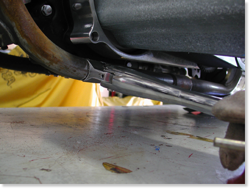
I sprayed the frame rail and the components with asilicone splatter preventative. It obstructs slag from sticking tocomponents. It also made the frame a slipper bitch. I tried settingthe stand end on a socket nearly 3 inches off the deck. Then Iconsidered the differing lengths of the stands and shifted to 2.5inches. Sin Wu was called, from the bedroom, to hold the stand firmlyin place. I marked it, with a grease pencil, then ground the edges ofthe bracket to be welded to the frame. Extra grinding took place toform a snug, metal to metal fit. In order to make all this work weneeded to partially assemble the kickstand without the ball andspring.
The easy-to-read directions called for disassembly, but we left ittogether and used it to hold the bracket in place for tacking. Beforetacking I backed the bike out of the clamp, holding it upright,positioned the bracket in the white grease pencil marks and leanedthe bike carefully until the stand rested on the flat surface. Itlooked cool, so we re-clamped the bike securely, held the stand inplace, protected the belt from hot slag and tacked the sucker withour Millermatic welder. Then we took the stand arm off the bracketand welded it some more. That would hold it securely until we torethe bike down for paint.
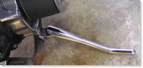
The Hot Match unit from Custom Chrome is a well madeprecision unit delivered show chromed. The instructions includedrecommendations to apply anti-seize to the spring and ball. Theyendorse using Red Loctite on the pivot pin threads. We didn’t becausethe bike would be torn down for paint in the near future. The armneeds to be placed firmly over the bracket and pushed into placebefore the pin will ease into the hole from the bottom. It doesn’thurt to have a spare set of hands and someone holding the bike.There’s also a pivot pin set screw to prevent losing that preciouspivot pin and kick stand arm, on a desert highway, in the middle ofArizona.
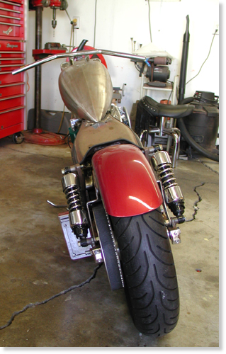
That’s it, except to mention that when we head to thepaint shop, we need to tape off the chrome bracket, so the painterwill paint over the welds but not the chrome tab.
As you can see this bike is damn close to the spray booth.I need to coerce Giggie, from Compu-fire, to ride his FXR out to theBikernet Headquarters with our mid-controls. Once the Joker Machinehandlebar controls are bolted to the modified bars, we’re ready for atrial run, then off to paint. Stay tuned.

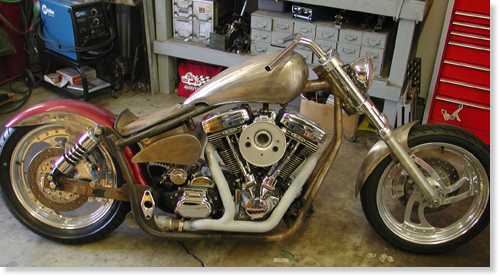
–Bandit
Sturgis 2000 – Part 4
By Robin Technologies |
|
The next morning, Myron and I got our asses in gear and loaded our scoots. Karl and Cheri were returning to Phoenix the long way through the mountains and Flag before getting home. We said our goodbyes and headed out. It was odd, or maybe not, that Myron and I were travelin’ without maps this year. We remembered the time we rode into Colorado by mistake and Mark the Warrior was mapped to the max. This was going to be an odd trip without a map. Sorta like sailing to Hawaii without a compass. We were flying by the seat of our pants. I babied the Blue Flame onto I-40 and tested it with my left glove. Not an ounce of vibration. It felt as if it was welded to the frame. I took it easy for another 40 miles then rolled it on. I had an entire fuckin’ tool box in the compartment of my handy-dandy bedroll. Hell, if it broke, I’d fix it. We rode to Gallup, N.M., some 98 miles to the east, pulled in and gassed up. A big Indian behind the counter told us, “Just stay on this street til you get to the Mexican restaurant — best food in town. Hang a right there and you’re on 666 heading north to Shiprock. Should take you about 2 hours.” “How about peach pie?” I asked. He just shrugged. An older gentleman dressed in Indian attire and turquoise jewelry looked at us through squinted eyes surrounded by leather-tough skin. “Two hundred miles,” he said. We looked at him, then at the younger man who ignored the bent over old dude with the knowing eyes. Something wasn’t right. We copped out and Myron bought a map. We rode the lumpy street for five miles until we came across the turn for 666 and the restaurant. Inside, we opened the map. He had purchased a perfectly good map of Utah. We weren’t going there, so I folded it and set it beside my napkin while I ate huevos rancheros, then asked the waitress how far Cortez, Colo., was. I’m not sure she knew what state she was in, but she delivered some mean salsa. After eating, we strolled out to the bikes and the waiter followed us. “You forget this, senors,” he said, handing me the map. I waited for him to return to the restaurant then shit-canned the map. We don’t need no stinkin’ maps. Myron’s wheel was clicking and it felt strange in the turns, so we had pulled it apart in Holbrook and found nothing. It sounded even worse as we pulled onto Highway 666 heading north, unaware of how far Cortez or Shiprock were. We just kept riding. The straight stretch from Gallop north was dry and hot, just under 100 degrees as we plowed into a junk yard of a town called Shiprock, named after one of the massive outcroppings in the desert. The roads were torn up like they were when we came through in ’97. We tried to find peach pie, but struck out, so we stopped at a McDonald’s for a shake. We were befriended by a small young Indian man wearing a camouflage hat and pants, a Vietnam ribbon and a tightly pressed denim shirt. He sat across from us, bent over in our direction and started the conversation like he had access to a couple of slices of black market peach pie. He glanced around the plastic franchise nervous like. His voice was slow and low and he peered at me like I was a passenger in De Niro’s “Taxi” movie. His eyes were deep and haunting. He whispered about the Harley he wanted to own more than anything, a Sportster he was planning to leave his wife and kids to get. I got it. If anyone heard him tell that story and it got back to his wife, he was toast. We pulled our chairs closer to the young man and listened intently as he explained his dream. I gave him a Bikernet sticker while wishing I had a Sportster in my bedroll. I would have gladly given it to the man. You could see the intensity in his eyes, the longing and the desperation. Apart from 15 liquor stores and the big Mac, the town had little to offer. On the outskirts there was a track of desolate homes indicative of the area. Each structure was about the size of a single, shoe-box mobile home. They were all painted brick red with white gravel roofs. A winding gravel path wound between them and small tufts of cactus. That was it. No garages, decks, driveways or carports. Each one was worn down by the sun and the wind that kept them engulfed in a cloud of dust. We noted the depressing atmosphere that loomed like acid rain over dying crops and got the fuck outta there. It was only 31 miles to Cortez. We rolled in before 3 p.m. and pulled up to the Best Western inhabited by the Hamsters. In fact, so many of the furry beasts were riding out that they had taken over two motels. My first impression as we pulled into the parking lot packed with dressers was a question. Where were all the custom bikes? The Hamsters have a reputation for being rich and riding nothing but $50,000 customs. From the looks of the parking lot, and the lines of black dressers, I had run into a HOG chapter on its way to the rally. My version of the dubious Hamster mantra has always been a club for custom builders and custom bike enthusiasts. As far as I’m concerned, that’s still the case, although as the guys get older, most can afford something comfortable for the long haul. Arlen Ness still rides a full custom all the way to the Bad Lands. And as far as being wealthy, most of these guys weren’t born that way. They worked for it, building a business that finally became successful. So now they have some money and deserve it. They also employ many riders, like Phil and Karen Day of Daytec. You couldn’t meet more down-to-Earth people. Arlen began his working life as a postman while building bikes in his garage. It’s only idiots like myself who decide to drop everything, go through a divorce and write books for a living who are on the brink of poverty. At least I can say I’m not a yuppie. The tank was still in place, Myron’s wheel continued to be round and roll as we pulled in just before a thunderstorm. Adjacent to the motel was a run down but functioning gym. Although the equipment was rickety and loose we hammered our bodies until we couldn’t walk and beat feet out of there. Every year on the way to Sturgis, Thomas throws a major party for his wife, Cheryl. Tom and Cheryl ride from the Bay area to Sturgis annually on one of Arlen’s luxury liners. He pushes that black beast with red and orange flames, with his wife on the back throughout the entire trip, keeping up with us hot rods. Quiet and unassuming, they plow down the freeway each year dressed in all black, riding hell bent to reach the Bad Lands. Each year at one stop, Thomas makes arrangements to feed and pour for all the Hamsters to celebrate Cheryl’s birth and their relationship. I don’t need to eat or drink that night. It’s enough to watch Cheryl’s face glow as he introduces her once more to the rabid clan. She glows with appreciation and love for her man. The “wind ’em up” call came at 7 a.m. the next day and a handful of riders jammed to breakfast, scarfed their eggs and omelets, asked for peach pie without success and rushed back to the motel to be with the gang as they rode out. We had 320 miles to go through Durango, over the pass into Silverton, up to Delta and into the mountains leading to Aspen. About 30 of us rode out together. There’s nothing more boring than riding in a pack. You can’t look around, check out the girls or look for peach pie. You can’t stop to pick your teeth, scratch your ass or look at the valley below. You can’t fuck around and do wheelies or someone will vote you out of the club. Well, we learned this the first year and then gradually worked our way to the front of the pack and disappeared over the horizon ahead. If a club wants to look impressive, they should meet five miles from their destination and ride together into town. Riding in a pack is fuckin’ dangerous but damn, it looks impressive. It’s the slow guy in the middle of the pack who falls asleep and wipes out the rest. Since I was still testing the handling of the blue chopper, I held back as we entered the mountainous curves leading out of Durango along the narrow gauge railroad into the steep mountains ahead. The tank held fast as we rolled through the sweeping bends and I warmed up to the morning sun. Soon I was trying to drag something as I careened around one curve after another, reminiscing about the touring chopper four years ago and how I had to shift my weight to keep the bike as upright as possible until I could get to a welder at a gas station in Silverton.
 As I cruised into the old mining town, I pulled into that same gas station and two of the guys who helped weld the swingarm into place were still there. One showed me his Knucklehead chop at the house behind the station. Some of the guys who hadn’t eaten breakfast were chowing down — another reason packs are a pain. So I grabbed my work gloves, saddled up and headed out of town with one Hamster wannabe behind me on his dresser. Little did I know that this would become a day to remember. We blew out of town and into the hills beyond. The trip at that point was perhaps the most picturesque, with rivers running through the pines below as we rolled through Montrose, then Delta and off at 133 toward Carbondale. We were making good time until we came to a small canyon outside of Carbondale, where the road was torn down to the dirt, grated and driven on enough to become washboard. The rigid handled it well, but I didn’t like the jarring impact on the tank. It seemed to scream as I bounced from one pothole to the next ridge and gully for three long miles. When we finally pulled onto the smooth pavement, I knew I was in trouble. I had a new series of vibrations screaming at me. Another 30 miles and we stopped for gas in Carbondale. We had covered 122 miles. Although I was richening the mixture due to the altitude, I put a mere 2.216 gallons in the chopper for 55 mpg. Aspen wasn’t far off. All we needed was fuel and 23 miles and we would be staring at a Jacuzzi, a pool and drinks. I looked at my cellular phone entrepreneur partner, Milo, and at my tank. Both the front and the rear tabs were broken and basically the tin tank with 25 pounds of gasoline stored inside was being held on with a piece of 3M tape a 1/2-inch wide. Milo shook his head, but I had to jinx the situation. “No problem,” I said, “I had to pry off the tape the last time. It’ll hold.” Yeah, right. Half way up the hill toward Aspen, I went over a slight bump in the road and the tank landed in my lap. Milo was in front and I lost him. I held onto the tank and pulled over. Setting it back in place, I stared at the wonderful paint work by Harold Pontarelli and pondered my situation. I wasn’t thinking immediate fixes. I was thinking about tomorrow and finding a welder, about the outcome of this run, and finally about Agent Zebra and the east coast contingent that was barreling up from the southeast. I had to make it, to fix the fucking tank and keep rolling. I was riding the first rigid chopper to Sturgis in, well, there were perhaps infinite rigids converging on the Bad Lands, so what was my point, anyway. Finally, I awoke from my nightmare, dug out a bungee cord from my bedroll, ran it over the tank, behind the gas cap and down to the front legs of the frame. It seemed to be stable so I rode on into town holding the tank with one hand. We were staying at a swank hotel in the center of trendy Aspen, but all the glitter and class only told me there wasn’t a welding shop in town. I had a mission. I unloaded my shit, checked into my room and picked up the phone. Myron came in about the same time, went to the room and tried to turn on the television. It didn’t work. That was a precursor to the events that lay ahead. I made call after call until I found a welder in Basalt, some 30 miles away. While I was calling all over the valley, Myron attempted to order something to eat, but the swank lodge didn’t start room service until 6 p.m. The welder I was looking for couldn’t be squeamish about welding gas tanks and I made sure to mention that pitfall immediately while calling around. With the welder lined up and a plan in place, I went to the bar to get a drink to calm my nerves. The bar didn’t open for another hour, but Myron and I glared at the barkeep until he found a couple glasses and filled them with Jack. We opted for an early dinner in town, so we attempted to clean up for the event. In the head, I stepped on a piece of glass and bled all over the slate floor. Then I attempted to iron a shirt, but the iron didn’t work. Myron, Milo and I went to dinner with Randy Aron of Cycle Visions in San Diego. I offered to pay for dinner, since Randy was going to run my ass around Aspen to find a welder, but my credit card was turned down. Plus the restaurant didn’t have any peach pie. Hell, the shitty tabs on the tank were my fault, not Randy’s. I was beginning to feel jinxed. El Swank Aspen hotel seemed OK. What else could go wrong? I discovered later that Wachovia bank was trying to track me down. Seems some biker had accosted my card and was riding to Sturgis on my dime, ‘cept that crazed thief was me. Randy, a young, stylish sorta rider is one of those Hamsters everyone complains about. He doesn’t look like the average biker. He drives a new truck and builds world class custom motorcycles. He’s talented and good looking but how did he get there? He started a plumbing business 20 years ago and worked his ass off. He took the risks, learned the trade, found customers, dealt with employees and finally became successful. Let’s shoot the mutha fucker. While the rest of the crew slept in their little sawdust Hamster Beds, I crept out at 6 a.m. and loaded the long chop next to Randy’s hand- formed dresser in his truck. We paid close attention to my sketchy directions and rolled out of the mountain pass down to Basalt where we took a right on Frying Pan Road and found a small industrial building. I pulled up to 3-D Iron and Mike Horn, a skinny, wrinkled man, greeted us with the bad news.
 Peering up at me through thick glasses, he said, “If it’s a gas tank, we won’t weld it.” Reaching for the tank that we had taken off the frame, wrapped in towel and duct taped for security, I noticed that liquid had filled the corner of the truck bed. On second glance, I became rudely aware that the petcock had come open and it was gas that soaked my clothes and my bedroll. I rolled my eyes and asked if we could pay for the equipment and weld it ourselves. “Nope, can’t do it. Insurance liability, you know,” he said. “But I will make a strap for the tank.” While I stared at the old welder in astonishment and tried to explain that I spoke to someone who had given me the green light, I knew it was futile. I could see a guy in the back of the shop bent over a bare metal trailer frame. He would only glance in my direction from time to time. Perhaps it was the guilty culprit who said to bring the tank down. Randy stood beside the truck and greeted several guys from the sheet metal shop next door.
 Most of the middle-aged workers were going to Sturgis and they readily struck up a conversation. The shop was neat and most of the guys had salt-and-pepper hair pulled into pony tails. Randy tapped me on the shoulder. “These guys will let me use their mig welder,” he said, referring to the team at T&E Marshall Enterprises Inc., makers of custom sheet metal and heating systems. We finally had a formula for success. The old guy from the crappie shop made the strap and drilled the holes while we emptied the tank and readied it for welding. Randy flushed the tin container with water, then held the tank mouth against the exhaust pipe of his truck until the carbon monoxide dissipated any gasoline fumes. The tank smelled clean and he fired his lighter above the mouth. Nothing. In a matter of five minutes, it was ready to weld safely. Randy tested the welder on a piece of scrap. The mig would do the job, but he wasn’t as comfortable as if he had his tig. The mig would have to do. Welding dissimilar metals together is a trick I was once very adept at. The 16-gauge material of the Sportster tank had to be mated to the 1/4-inch thickness of the strap and Randy went to work. Sparks flew, metal crackled and paint sizzled as he welded the tab in several places.
 Since I had brazed the original tabs in place, the braze melted and flowed into the welds, causing them to sputter. We let the tank cool and filled it with water. It leaked, my worst nightmare. Even worse than breaking tabs or having a loose tank was the threat of a leak. Randy tried again, but the leaks were coming from under the tab where it was impossible to reach with the welder. In an attempt to fix the existing leaks, Randy blew a hole in the tank. He worked on the hole, then I suggested that we braze over the welds to seal them. It wasn’t a bad idea, but a torch and braze was going to generate much more heat to a wider area and Randy was considering the damage to the paint. So far, Harold’s creativity was unscathed. Finally, Randy and I began an hour job that could have taken 15 minutes. Because of the bondo smoke and the steam from the wet rag Randy held close to the area I was attempting to braze, the torch kept blowing out. It took forever to coat some of the welds with brass. We checked the tank again with water. It seemed to have sealed. We packed up and headed north. Checking tank leaks with water is like filtering your gas with screen door mesh. It’s an indicator, but not a good one. I felt that the only way to guard against gas seeping through the welds was to seal the tank. We had some discussion about saving the tank and welding on it in the future with sealant inside, but finally settled on trying to find some Custom Chrome Tank Creme, a three-stage process. We went to a small diner for lunch and I got back on the phone.
|
Sturgis 2000 – Part 4-3
By Robin Technologies |
|
That last 25 miles were the worst of the trip. It rained off and on as the traffic became thick as mud on your boots. Lane splitting is not allowed and when we attempted to play ignorant travelers, motorists tried to hit us. As the sun broke over the parking lot of cars, the humidity rose with the mercury. Of course we got lost at one point, found the Two-Wheelers shop and ultimately the hotel. There was a major party planned for the 25th anniversary of the shop, but the threat of rain and the 450- mile trip to Sturgis the next morning forced us to take it easy and hit the hay early. We tried a local restaurant for grub, but they still didn’t serve peach pie. The next morning, Myron and I were on the road by 4:30. An odd feeling swept over us as we rode Highway 25 in the dark. In the rolling fields and wide open spaces of Colorado, it was as if we were lodged on the brink of the city. There wasn’t a row of houses or an industrial park once we turned north and it felt good. We rumbled for 90 miles until we arrived at Cheyenne, Wyo., for breakfast. We hit the road for another 75 miles and pulled off in Wheatland where we refueled and had one of Myron’s safety meals and coffee. He works out constantly and feels that his success in the gym is attributable to his intake of protein. He doesn’t eat a lot or poorly, but often and bushels of protein. As we walked out of the restaurant, we were met by Cheryl. Tom’s bike had a broken shift lever and he was working on it. “How the hell did you get here?” Myron asked. “Uh,” Cheryl muttered, not sure what to say. “What time did you leave?” I asked. “6:30,” she said. We looked at each other in dismay. Myron jerked on his gloves. “Let’s ride,” he shouted, “We’re burnin’ daylight.” We spit dust and rocks as we blasted out of the gravel lot and onto the highway. Suddenly he was hell bent for leather. We stopped just for gas in Orin and headed east on 20/18, blasting toward the small town of Lusk, Wyo.
 At the end of town we stopped for another safety meal. We had 130 miles to go to get to Sturgis, but the roads would narrow and we’d have to slow down. Across the street the bikes were lined up in front of the western bar. I liked this town. It’s small but has some action going for it. As we turned toward the door of the Del Rey Cafe, Milo strolled out the door pickin’ his teeth with a tooth pick. “Damn!” Myron said and almost abandoned his safety meal stop. “What the fuck are you doing here?” Milo shrugged, straddled his all-black dresser and took off. The waitress would melt a good man’s bones with her silky, fair complexion, even lighter hair and brilliant blue eyes. My words were stumbling when I asked for peach pie, but I lost all interest when I discovered that she had just run out. “You mean you didn’t save me a slice?” I shouted, throwing my tan gloves on the table. In Newcastle we stopped momentarily for gas, but as we paid our ticket we noticed Hamster Jeff pull into the station. Myron grabbed his gloves and headed for his Dyna. “Fuck the peach pie,” he shouted again, “Let’s ride.” I tried to holler to Jeff as we headed out of the station and hit the highway toward Four Corners. We were in a race now, and although Myron said to most riders as we left them in bars and gas stops, “Keep it under a hundred,” this time it was different. If we had open straight roads ahead, throttles would be pegged to the stops. He couldn’t figure out how these bastards who left the motel two hours after we did were catching up. Hell, we were rumbling along at 85 plus, but we had 14 meals to their one cup of coffee. What the fuck? Now we were in narrow canyons weaving through packs of bikers heading to their homeland. Again the chopper handled the curves as if I were on a rice rocket, dipping and bending with each bank. Each gas stop was spoke to spoke with lines of motorcycles to refuel. Each bar looked like a popular biker hangout from Southern Calif. on a Sunday afternoon.
 They were coming from all directions. The rumor of afternoon thunderstorms had us pushing the envelope. Our bikes were a mess, but they were running and we were ready to hit the home stretch for our abode in the Bad Lands. Finally, in Spearfish Canyon 15 miles from home, we slowed and enjoyed the Jack Pines and the bustling brooks that bordered the winding road. We were home. Home to the biker, the outlaw, the bandit and to every fucking rider in the world who enjoys open roads, beer, broads and peach pie. Now if we could only find the girl, or at least a piece of pie.
 –Bandit PS. Zebra had arrived four hours earlier. We immediately gathered up the boys and found the only bikini bike wash in town. Following is a couple of miscellaneous shots from Sturgis 2000. It was a helluva year.
|
Sturgis 2000 – Part 3
By Robin Technologies |
|
The next morning, after breakfast at Stan’s diner in Scottsdale, we rolled north toward Payson on our way to Holbrook. Stan’s is a small joint in a dull rectangular building downtown, that Stan tried to spruce up with adobe chairs and tables. A skinny waitress came to take our order but since this was Myron’s regular digs, he went directly to the chef in back and nodded. That was enough. The chef knew what to do. Karl and I attempted to order with smiles on our unshaven mugs but the waitress was dry as toast, and edgy. The cactus twig of a woman could not comply. We had been trying the low carb regimen and Karl had lost 40 pounds, but she couldn’t allow us to substitute potatoes for tomato slices or cottage cheese for toast. We ended up ordering everything a la carte. At first our easy-going hackles were raised because we wanted to hit the road early and slice away some dusty miles, then eat in some strange hole-in-the-wall joint in nowheresville, Arizona. But the more we irritated her, the more fun we had. She was spitting in our scrambled eggs by the time we finished with her, but it was worth it. Phoenix is a strange city. Surface streets are straight and packed with stoplights. We headed out a country road through one boulevard stop after another. Suddenly we were out of the flat city and into the country, winding into the Mazatzal Mountains on Highway 87. At one point we pulled off the highway at an All-Bike junkyard Rye, Ariz., a town with a population of 300. There were acres of bikes rotting in the elements.
 At this point there were four of us. Myron was riding his black, detailed 2000 Dyna with a 95-inch kit, stretched tanks and a custom windshield. As usual, his bike was immaculate with chromed Harley mags and diamond cut cylinder fins. He had soft bags beside the rear wheel and a bolt-on sissy bar with bags attached. He was one comfortable mutha as we cut through the canyons. The man generally wears a long sleeved T-shirt with a regular T-shirt over it and his HAL vest, plus a scarf. He rides fast and tight. Myron has always reminded me of longtime friend George Christie, the president of the Ventura chapter of the Hells Angels. Although Myron is a massive weight lifter, and George trains in martial arts, the two men are similar height with jet-black hair (graying some, now). Both men are born leaders and strong riders. Karl was on his lowered Softail with drag pipes and drag bars, with his buoyant wife of 25 years at his back. The couple have raised three gigantic kids, consequently Karl doesn’t have new bikes yearly, custom paint jobs and chrome. He’s saddled with a non-working mother and three money-soaking monsters to raise and he’s proud of every minute he can keep the clan in college, clothes and wheels. I respect the fact that Cheri stays home with the kids. It’s a full time vocation and perhaps the most important job on the planet.
 The mountains were striking and I’m constantly amazed at the Arizona beauty. The state is diverse and open. No wonder people are lining up to move there. It’s a killer place to live. The diversity is unreal, from the arid, open, hot-as-a-mutha desert to the rolling, pine-strewn mountains and the Grand Canyon area. We stopped in Payson for gas. I had clocked 87 miles and took 1.9 gallons. I was still rolling along even in erratic terrain and getting 45 mpg. I bought a cheap tire gauge and checked my tire pressure. Brownie had jacked it up per the tire specs, but I was more flexible and had another priority — the ride. The front tire being on an extended front end didn’t need 50 pounds of pressure and the rear 180-18 Avon needed to be as soft as possible, so I dropped the 40 pounds to less than 30. As I stood there, Cheri chatted away about one thing or another, constantly making sexual references to the most absurd articles. She somehow found honey mustard dressing sexual, or elevators, though I could understand her phallic reference to pickles. As we moved into the hills, the incline felt good to the 98-inch S&S motor. Rumbling up a winding incline, we found ourselves behind several motor homes and a logging truck. When we hit a passing lane, two tourists melded to the right and the logging truck and one camper stayed to the left as if in a 1/4 mile they could pass the other dog-slow travelers. I down shifted and poured the fuel to the stroker, which climbed on the other vehicles like they were standing still. The lumber truck was barely reaching the rear bumper of the motor home when I split between them. I blasted over the rise ahead and began a high-speed decline. I slowed slightly to let the others catch me, but they didn’t come. I slowed some more, then suddenly noticed a thundering 18-wheeler bearing down on me. I had upset the trucker and he planned to flatten my ass. The rigid Blue is light, and I was discovering lightning-fast throttle response. I bolted forward. I spun the throttle, again, and it came alive like the crack from a high velocity .22. Then I noticed a new vibration. It was coming from the tank. The truck was trying to gain on me again, and I slipped the polished 42-mm Mikuni more fuel and she responded like a tongue to a sensitive clit. The bike jumped and roared ahead. Again, a rattling screamed at me from the top of the frame and I pulled my gloved hand off the left grip and put it on top of Harold’s paint work, which glistened in the sun. My teeth immediately responded to the touch. Something was wrong, but I had a semi barreling down on me and I couldn’t stop. I didn’t want to pull over and give him an open target so I pressed on the tank with my left hand and pushed harder on the throttle with my right. I raced past the signs indicating a dangerous decline ahead and warning truckers to check their brakes. The guy behind me had no notion of using his as he sped to catch me. Fortunately, I could outrun him, if I were riding a bike built for mountain riding. This was my first opportunity to test the handling of the 38-degree raked frame with the 6 degrees in the Weerd Bros. front end. I had specifically built in plenty of ground clearance by cutting the Samson pipes and lifting the front header. There was nothing on the left to interfere with the road and I had a solid six inches of ground clearance underneath the frame. As I leaned I felt the bike want to tumble so I poured more fuel and the front wheel tracked the corner smoothly. The next corner was well marked for speed and curvature. I dipped low and accelerated. Although the rake generally, with speed, wants to force the bike to go straight, the additional rake in the triple trees minimized the trail and the front end adjusted easily to the turn, but I was trying to hold on to my vibrating gas tank at the same time. Another series of turns were dead ahead and the screaming logger was shifting gears 30 feet from my rear Avon. He knew the road better than I did. I took the shift as a signal of manageable turns ahead and turned the throttle. The bike jumped forward and I released the tank to handle the curve. To my left were open oncoming lanes through sliced mountains. To my right was a sheer precipice and a majestic valley a couple thousand feet below. I pushed the Blue Flame and it responded like a thoroughbred. It felt strange. I had ridden choppers for years, but in the last decade I hadn’t ridden a bike with this length of front tubes. The Jesse James touring chopper had a severe turning radius restriction with the bags, but this machine seemed to have no bumpers, no drag, no pegs that prevented me from leaning it closer to the asphalt, so I pushed. The only thing that would hold me back from making the next turn was Avon traction, a flexing Daytec frame or a squirrely front-end. I seemed to handle turns to the right easier than to the left, and I dipped as the curve unveiled itself. The truck was right on my ass as I hit the 35 mph turn at 60. The most terrifying aspect of any turn is the visual. Can you see the chamfer and the complete arch? Is there a mountain on the inside preventing visibility? Are you heading downhill? Downhill racing is the worst. You can let up on the throttle and the bike won’t slow down. That’s the last thing you need when you realize that your bike cannot make the corner. I needed deceleration and it wasn’t there. I had pulled away from the truck, but the tank was singing a violent tune. I ignored the horrible vibration and dipped the machine to the right. To my amazement, it went over easily. Nothing scraped, skipped, twisted or jiggled. The tire remained firmly planted to the road’s surface and I accelerated through the turn and into the next one. The truck loomed behind me except it wasn’t barreling after me this time. The postings along the side of the mountain warned of the steep slope, brake testing and slow trucks. The driver had chosen to ignore the warnings and careened after me, but now in the rearview mirror the trucker’s load seemed out of balance. The massive logs were jostled. The truck leaned at an odd angle. The driver had abandoned the pursuit in favor of saving his own neck. Smoke poured from the brakes as he tried to control the 80,000-pound vehicle before he encountered another curve along the perilous slope. I glanced at the valley below and decided he was more of a threat now than when he was pissed and in control. I turned up the heat and headed quickly away from the collision-bound truck. We had several junctions ahead, including 377 to Holbrook, 277 to Snowflake and 260 to Show Low. With each curve I was forced to test, I became more confident in the Daytec chassis and long Weerd Bros. wide glide front end. I had never owned a chopper that handled with this much ease. I seemed to be able to dip the flaming scoot over so far that my calf was parallel with the pavement. I hit the town of Heber where we had planned to stop for a piece of peach pie, but I blew right through. I passed the 377 turn off and prayed that the trucker survived, but was on his way to Snowflake. I split off on 260 toward Show Low and quickly found a safe place to pull over to check my tank and wait for the others. The rear tab on the tank had broken and the vibration between the remaining tab was eerie, but with the 3M weather stripping holding the tank to the frame backbone and the front tab in place, all appeared secure. Myron pulled up with Karl and the emotional Cheri shouted, “That truck was after your ass.” We only had another 30 miles to go but we hit a hardware store and, based on expert breakdown recommendations from Karl and Myron, I picked up more 3M stripping, JB Weld, sand paper and some grommets. I rode carefully for the final 30 miles into Holbrook where we copped a couple of rooms and prepared to operate on the Blue Flame.
 I almost had to pry the tank off. The rear tab was toast and I spent an hour cleaning it. I mixed and spread the JB weld, put down new 3M weather stripping and reinstalled the tank. It was time for happy hour and we walked to the local cowboy/sports bar across the highway. There’s an odd sensation that comes over a rider with a busted machine. It’s as if you know you must hike to the top of the hill, but you’re bleeding. You know you’re going for it, but not sure how you’ll make it. Still you keep moving forward. Holbrook was our stopping point about 250 miles out. The bar was cool and for some reason, perhaps the unrelenting heat, we ordered margarita after margarita, then chicken wings, chicken tenders and more wings. Those little puppies were smoldering but went down like chips at a Mexican restaurant. We munched as if we weren’t going to eat for a week, then went in search of peach pie. Why is it that once out of California, fresh vegetables and fruit seem impossible to come by. If I couldn’t have sex, I wanted peach pie, and for some odd reason, it seemed as rare as a whore in church.
|
Sturgis 2000 – Part 4-2
By Robin Technologies |
|
 The Harley shop in Green River didn’t have it, nor did any of the other bike shops in the valley, but there was a shop in Aspen. It wasn’t in the phone book and couldn’t be reached by directory assistance. I called the Harley shop back and was given the number for Aspen Custom Motorcycles. I dialed and there was only an answering machine. Tired and dejected, we rambled back toward town. During one of our last installation attempts, we broke off the stud that held the rear tab in place. Now we needed an auto parts store for a large hose clamp and some rubber insulation to prevent the clamp from tearing through the durable powder coating finish. We pulled up in front of a Napa auto parts store and parked beside a blue and silver pickup with Krylon letters across the back window, “Aspen Custom Motorcycles.” Inside, a thin man with dark hair and youthful features leaned over the counter wearing a black Aspen Custom Motorcycles T-shirt. I introduced myself and he asked us to follow him. Two blocks away, this guy had his shop set up in a single storage unit stall (970) 544-9419. His undercover shop was complete with three stage creme sealer and we bought his only kit, thanked him and hauled ass for the Swank Hotel. In front of our room was an outdoor corridor leading to the bar and outdoor pool. I picked up several towels, borrowed a large bucket and we went to work. The first stage was a mixture of water and a strong detergent that was supposed to soak in the tank for four hours. We didn’t have the time and let it set for an hour. In the meantime, the guys in Randy’s room where having trouble with the plumbing. After I flushed the toxic mixture into a bucket, I poured it down the toilet in Randy’s room. I knew I should have stopped, but I was beyond the point of no return. I returned to the bike for stage two – flushing the tank with a strong solvent. Again the remnants of the explosive liquid were drained into the toilet. Meanwhile, hotel maintenance men and managers descended on Randy’s room, where a couple of riders had set up their joint rolling station. Plungers, tools and snakes were moved from room to room. Four rooms were effected and they were going to have to snake down from the roof. Randy shook his head. “Won’t work,” he said and poured the final stage of thick milky fluid into the tank. This process included sloshing the creamy liquid around the tank for 10 minutes, letting it set for 20, then sloshing again before draining. Randy sloshed and coated the lining of the tank for what seemed to be hours, making sure every crevice received its fair share. By this time evening was upon us. The tank was supposed to dry for 24 hours. I didn’t have time and Randy suggested that we use a hair dryer to speed up the drying process. The instructions specifically warned against the use of hair dryers because the final process was extremely flammable. Randy continued draining the thickening substance back into the bottle it came from, as we pondered the question. At one point, we tried putting the tank in front of the air conditioner to augment the flow, but there had to be a better way. Finally someone hit up the maintenance crew for a shop vac. As the sun sank, we started sucking the fumes from the tank outside our room.
 At one point, two girls showed up, one 22 and the other 27. They wanted to smoke a joint and party some, but the fumes held them at bay. Both were wearing shorts and tank tops and carrying shopping bags. One included a couple pairs of spiked heels that they quickly unwrapped and promised to sport for us. One had on a top buttoned up the front over no bra, and her tits were pressed so hard against the mint green fabric that the heavenly mounds creased the material. When she leaned over to slip on the shoes, we gasped in unison. Whatever it is that makes a woman’s body magic to a man, is a wonderful thing unless abused by either party. If a woman minds that a man gawks at the flesh exposed by too little clothing, she should cover herself. These girls didn’t mind. In fact, they enjoyed it and wanted more. We could have given in to them except we had a mission and a deadline. After the girls asked some probing questions and we didn’t respond appropriately, they rolled themselves a doobie and departed. There was another problem with nubile girls finding their evil ways into our lives. We were staying with 100 of our closest, most gossipy friends in the same goddamn hotel. Speaking of gossip, I hadn’t heard from Zebra for two days. He was supposed to hook up with a pack of riders in Tennessee, and perhaps they roasted him instead of a pig. I didn’t know his whereabouts, but I kept calling his cell phone hoping to hear the number had been permanently disconnected. At 6 a.m. Friday, the phone rang. Larry the mobile mud slide maker was leaving his room to meet me in the parking lot to lend me gas. I was hoping to sleep in, but noooo. I wrestled my ass out of bed and out to the bike with the tank. After setting it on the bike, it was difficult to tell that it had been through hell the previous day. I mounted it, hooked up the lines and went back to bed. I told Larry never to call me at 6 a.m. again and to keep his gas. I wanted to let it air for a couple more hours. At 9 a.m. we put gas in it for the first time from Howard’s truck, just a quart. We loaded up and hit the first station. We were Denver bound. Some of the guys were heading into the pass above, but rumor was that the straight shot was down to Green River, over to the 70 Freeway and into Denver. It was 30 miles out of the way, but we chose the straightest shot. The freeway is only two lanes wide but it meanders along railroad tracks and rivers toward Vail. We stopped for gas in Eagle and were passed by 30 Hamsters blasting onto the freeway. How they beat us I will never know, but I sent my navigator his walking papers the next day. We caught the furry beasts outside Vail. Traffic began to bunch up and we kept riding faster, splitting lanes and running the gauntlet between the very fast cars and extremely slow trucks. Treachery was all around us as we crested a pass and could see the dots of a pack of bikes in the distance. The tank was holding and the bike hadn’t burped, coughed or sputtered. It could handle anything I dished out. I turned the throttle and it responded. About 25 miles outside Denver we blew past the guys in yellow and another couple miles down the road it began to rain, then hail. We ducked off the freeway, pulled on our slickers and found a log cabin watering hole.

|
Sturgis 2000 – Part 2
By Robin Technologies |
| That afternoon, I finished the weekly update and jammed for the tilting garage. Nuutboy had already broken under the extreme pressure and hauled ass for foreign shores. Wrench checked into rehab for the 24th time.
He had been awake for three weeks and was beginning to look like the guy from the “Living Dead.” Japanese Jay threw up his hands, jumped on the bike from the Harley fleet center, and hauled ass for the border. Renegade bitched and moaned, but under his breath, after smoking several joints, said, “Nice bike.” We knew then I was good to go. I dialed Giggie in a frenzy, “Could I have knocked the clutch hub loose?” “Don’t sweat it,” he said, “It’s tight, but what about the plates?” We had installed a plate wrong and metal-to-metal grating was taking place. With that fixed, I moved on to a shim to prevent the starter jackshaft from peeling away the aluminum on the inside of the BDL support bracket. I was beginning to feel that tight feeling of a motorcycle without any loose ends, except for the speedometer, which I was holding in my hand behind the top triple tree. It seemed to fit and I ran the cable. No problem except the cap holding the cable into the bottom of the speedo didn’t seem to work. It came with another cap and that didn’t work either. My mind raced with options. Throw it into the street and forget it? Find something with the correct thread size and make a cap? That seemed to be an option and I jumped into the flamed T-Chicken and roared to the marine store.
The threads were fine and the same size as any toggle switch nut, except nothing was available except toggle switch waver nuts. I tried the hardware store. The owner who never smiles, then the employees, the Asian with one bad arm who doesn’t speak, and the Hispanic who is always eating burritos no matter what time of day it is pointed at the fastener wall and ignored me. I searched and searched until I had to ask for help. They shook their heads and I searched some more. I screamed, they hid behind paint cans. I couldn’t believe that they would have every size 1/2-inch nut except this one. I roared off to Neptune’s electronics. The owner, in the shop that hadn’t changed since the ’50s, looked at me and said, “Yep, had some of those, but I don’t know where.” He didn’t and I left feeling dejected. It was almost 4:30 as I tore along the harbor while dialing the cell phone. “Phil,” I said gritting my teeth, “You know anything about speedo cables?” “Yep,” he said, as he eyed my CCI cable, “it’s easy to get these things wrong,” and referred me to Drag Bike Engineering on Artesia Boulevard in Gardena. I drove up Western Boulevard, which sucks. It runs north and south through the middle of the Palos Verdes Peninsula. It’s a four-lane boulevard that’s bordered by every goddamn franchise jip joint, fast food place, square boring store front on the planet. The only item it contains more of is stop lights. So I drove, and stopped and drove, and the street narrowed. I rolled out of San Pedro into Lomita, then Torrance and into some places I had never heard of when I finally hit Artesia. I hung a left and there was Drag Bike Engineering, a clean, well-stocked shop. Phil told me to ask for Jim and I did. Only two knowledgeable riders were in the pristine shop and one said, “Don’t I know you?” I looked at him hard and thought about all 30-some years I’ve been riding and stumbling in and out of events, parties and runs. I hadn’t a clue. “Yeah, a couple of years ago at Kern River,” he said, smiling. The most vivid memory of the Kern was hitting a guy in the face with a bottle of Cuervo Gold ’cause he pulled a knife on one of our guys for the second time. I warned him the first. It wasn’t him, thank God. I introduced myself again, apologized for not remembering anything except what was on my check-off list for Sturgis and asked about the cable. Jim came out from the back. “Yep, those cables are tough to match.” He wandered over to his rack, pulled off another CCI cable and tossed it on the counter. “See if this will do the trick.” I pulled my knife and began to slice at the plastic wrapper, immediately slitting my thumb wide open. Maybe the pressure was getting to me. The cable was perfect and I bled all over his counter. Jim gave me a Band-aid as his partner put a plastic coating over the braided cable and I hit the road. Good byes are tough, sometimes, and we bounced joyously into the wee hours before she slipped from my arms and into the harbor night. Blissfully high on several stimulants, I attempted to mount the speedo. I had to drill a 3/8-inch hole in the top triple tree. I did so crooked and with that disappointment dampening a near-perfect evening, I went to bed. I was beginning to cut into overtime. Had the Agent left from the east coast? I could care less. He had his bike a month ago. If he chose to dick around, well that was his problem. I had my list to contend with. The final nights were spent saying goodbye to a woman who had made my summer come alive. She was different than so many women I had met. There was no pretense. She had been born and raised in San Pedro and she could give a shit less about Hollywood, stardom or money. She lived a simple life as a single mother of three kids while looking after her aging father. She had roots and was securely attached to them. There appeared to be no agenda, although since splitting from her abusive biker, druggie husband of 15 years she felt ripped off by him and life. She wanted the family /husband and ordinary home and hated the fact that it all was torn from her. There was also something nasty about this woman who seemed to glide along on tender feet. Her dark wavy hair looked wonderful no matter how she combed it. It seemed astonishing that if she grabbed it and shoved it into a rubber band she suddenly took on a whole new look, yet just as beautiful as the one before. She also had a thirst that once unleashed seemed to permeate her being. If I cared for her, she blossomed, like a brilliant sunlit bloom. And so her sexual appetite was replanted in fresh soil to flourish. It’s as if a woman needs only to have the door carefully opened and the bud goes wild. As I sat back and watched this flower bloom again and again, I relished the minutes we had together. Although my body was floating on air, my mind was aghast with the trivial elements of the trip. I awoke with a start. Only 24 hours to go. She held on as I threw socks over my shoulder into the pile burying the Bandit’s bed roll and began a hectic countdown. The morning began with calls to the patch maker.
He gave me some bullshit story about a supplier overseas after the son of a bitch told me they did all their work in-house. I made my way to the garage and reinstalled the speedo several times, corrected the clutch and then hit the spare bedroom and the pile of laundry over the bedroll. I loaded it and unloaded it, checked and rechecked. Then I slipped the heavy bag above my headlight. Tie wraps usually work well to hold it in place, but sometimes not well enough. It seemed to shift six inches off center as soon as I stood the bike upright. I fired the loaded bike in the late afternoon and headed for a refueling station. The Blue Flame had less than two miles on the new speedo when I pulled it back into the garage for final tightening. It was good to go and she was about to come. I locked the back door. The next time I would open it would be to head out at the crack of dawn the next morning.
I had planned to wake up at 4 a.m. and leave at 5, but when she rolled on top of me, for some reason I couldn’t move or toss her aside. I didn’t struggle, but as the sun broke above the harbor like a fresh egg cracked into a hot frying pan, I pushed the rigid into the growing warmth and fired her to life. I pushed off with a full tank of gas and no idea of my capacity or mileage. I rolled along the harbor as the 18-wheelers were beginning to rumble in and out of the teeming container docks. The tug whistle blasted above the sound of my modified drag pipes as I rolled onto the freeway heading north to the 91 and north again to the 605 and north again to the 10, where I would set for 430 miles, heading east to Phoenix. I have a code, that I like to cut through at least 100 miles the first leg out. Depending on the length of the day, I slice off smaller chunks as the day dwindles. You know the saying: “Let’s ride, we’re burnin’ daylight.” My first stop was 101 miles out and the tilted, 3.2- gallon gas tank took 1.841 gallons. That was 54 miles to the gallon. I stopped just past Yucaipa, and I thought of Rip and all his trips from Yucaipa to the Valley. ‘Bout 100 miles in rush hour traffic to work on a motorcycle is nothing to sneeze at, and it’s surprising that something other than motorcycles killed him. As I fueled, I started to strip off the outer layers. Since it was cool when I left, I had on thermal undies, Wranglers, an Excelsior-Henderson sweatshirt, the Prison Blues denim and little Joe’s leather vest, except this one I ordered in brown. I had to wear something different and it was cut larger than the first black one. I would like to be able to afford another lambskin shirt out of brown, also. In the process of stripping off the jacket and strapping it to my bedroll along with a spare primary belt, I bungeed the bedroll to the trees and bars and it quit bouncing around.
I rode another 30 miles and came across Hadley’s, a famous spot for date shakes. Unlike my usual gotta-get-there demeanor, I pulled off the freeway and took a break. Already I was feeling solid about the bike as I stood and watched the sun turn up the amps. The outlook for flat Phoenix was 115 degrees of misery, and I would be riding into the pressure cooker just when the flame reached its max. Behind the scheduled departure time by one hour, I felt both the pressure to keep moving and the release of being on vacation. Yet was this competition with the bastard on the far coast a vacation? Or was it an endurance contest to test my cracked and bruised bones to the Black Hills on a rigid? A rigid? I pondered the question. I hadn’t noticed any discernible terror permeating my 52-year-old muscles or frame by the rigidity of the structure I was riding. Was I deceiving myself about the ride or was it acceptable? Without checking a damn thing on the bike, I gulped down the mixture of dates, bananas and ice cream and hit the road. Damn, that was delicious, but I had a desert to cross on a new motorcycle, through a no-man’s land during the sizzling summer. I kept telling myself that this Sturgis would be different. I was riding a rigid. I would take it easy. The bike needed a break-in period, it needed to be checked out, watched over and I wasn’t no spring chicken. Fuck all that shit. I had worked hard all summer building two bikes. I’d been riding bikes before I drove a car so I wasn’t going to change my style. I rode hard and the bike was going to be forced to handle it. I kept moving up the freeway, through Palm Springs toward Blythe, on the border of the sunshine state and Arizona. For me, Blythe represents reaching the outskirts of Los Angeles and escaping into the forgotten lands of a desert, of Indian reservations and not much else. I like that. I enjoyed the two-lane road that meandered through the low shrubbery and intermittent cactus, surrounded by miles of fine white sand that stings your eyes and catches in the sweat on your sunburnt brow. There’s a silence out there, a solitude that’s hard to find in L.A. Sure, once out of the city there are other counties, other communities, but it’s all the same. One franchise after another, shouting at travelers from the sides of the freeway. I needed to get away and I don’t feel as if I’ve gone a mile until I hit Blythe. It’s a small, sun-bleached truck stop in the middle of nowhere where a biker can refuel and have a meal, then ride a mile to the border and shit-can his helmet. The remainder of the trip would be helmet free. I pulled in under a canopy at the Chevron and refueled. It was hot and I took my slicker, spare drive belt and Prison Blues jacket off my bedroll and unzipped the tool pouch. I have a pack of Allen wrenches in the pocket. I went in the station after refueling and stretched in the cool air of the interior. The two girls behind the counter gawked at the road warrior standing before them and hurriedly gave me the change for my jug of chilled water. I could feel them checking me sideways as I walked into the sun. I had passed a caravan of VW drivers on some sort of product test. The group of Europeans compared notes about the cars and tried to discuss my stretched chopper with me. I don’t speak German. Hell, even my Spanish is rough, but I made do.
I tried my best while adjusting the peg angle on the Joker machine forward controls, to tell them the code of the west and how choppers had taken California from the Spanish. They wandered off pointing at the Blue Flame in amazement. The bike was handling well and the ride was superb. For A rigid, I seemed to be floating on air. I must give the H-D folks the credit and Nuutboy, the man responsible for narrowing the seat pan and building a support frame under the seat. There was no side-to-side slack. The up and down movement was unhampered and the springs carried my weight without a problem. When I first hit the road, I was concerned about my fat-assed weight on the two spindly coil springs and tried to sit forward on the seat to prevent fatigue and over extending their life. I realized before long that there was no way I was going to put my riding position behind the longevity of the springs. I couldn’t stay focused on preventing trucks from running over me.
The Joker Machine pegs were well designed and executed. The were designed to allow me to change the angle in case my feet were vibrating off the pegs and change the pivot angle. I made one of the pegs flat and slightly lifted the heel rest on the other. It was a test. The polished chrome surface of the pegs was slick and my old Niki hiking boots were dancing off the surface, precariously close to bouncing off the brutally abrasive concrete below.
I chose to wear these leather, low-cut boots for a couple reasons. I generally wear leather cowboy boots. Here’s why: If you wear tennis shoes or rubber soled boots and need to put your foot on the pavement while the bike is rolling, anything that sticks will shove off to the rear and you’ll immediately find yourself bouncing along on your knee. If you can’t put your foot down in an emergency, what the fuck good are you? Many riders wear rubber-soled boots for a specific reason: They’re resistant to oil and chemicals. If you’re in dust or dirt and trying to push your machining around, you get better traction (you should be riding, not pushing). But that’s slow-speed shit. To me, it’s the fast shit you need to concern yourself with. Your boots should have tough but slick leather soles for serious survival. So when picking my wardrobe for the run, I wanted something with some give for the slick foot pegs. Leather soled boots would glide right off. On the other hand, I wanted something hard enough to be less than tire-sticky on the pavement. These hardened Nikis seemed to do the job. Fortunately I never had to test their high-speed capabilities. With the pegs adjusted and enough water in my gullet to keep me from passing out in the heat, I rolled out from under the shade of the gas station canopy and back into the blistering sun. I pulled off the side of the highway under a sprawling billboard welcoming me to the Arizona desert ahead. The sign said freedom to me. I wanted to yank off the jockey-styled helmet and throw it in the gulley with the creosote, tumbleweed and empty junk food containers that line Interstate 10 all the way to the east coast. I let my helmet go a couple of years ago in Utah on my way to the rally, but this year my budget was tight. It took every dime to build the bikes and pay the bills before I headed out. I left Los Angeles with only a $100 bill in my Wrangler pocket. My brother in Phoenix would refill my run fund because I had put our Sturgis motel on my credit card. I would take his cut in cash. Enough cash to keep me going, I hoped. With 160 miles left to make the 429 to Phoenix, I kept rolling. I was already confident that I could make 100 miles without hitting reserve, so I cleared the trip gauge before I left each gas station and it acted as my gas gauge. As I rolled into the desert, the sun was reaching noon high and I thought about the machine beneath me. There’s a sense of fight and might or doom and gloom in each machine I ride. You just know after a couple hundred miles whether the bike is good for the long haul, hanging on for dear life or crumbling under your feet. It’s a matter of sound, vibration and a feel for the driveline balance. I had worked hard to keep the driveline poised, but I had no concept of how the Daytec frame, the Weerd Bros. front end or the Road Wings wheels would stand up under the continued strain. I had been disturbed at the poor pre-load spacing of the Timken bearings in the wheels. The company seemed to be floundering. A collapsed wheel at 80 mph would make me wish I had skis strapped to my ankles. I had allowed a longtime friend of mine and a man who understands and owns long bikes ride my bike during the break-in period. I rode along side him on his black West Coast stretch. I concentrated on watching the frame and front end on the uneven surface of the Santa Monica Freeway. I was surprised to see a 14-over front end work that well. The polished aluminum tubes glided effortlessly up and down after I had installed six ounces of heavyweight Rev Tech oil in each already-wet tube. If the front end had been dry, we would have poured eight ounces in each. The wheels were hard to read. I hadn’t balanced the front, but it didn’t seem to hop on the grated concrete. When the pavement was smooth, the bike appeared to glide along. As I reached the California border, I knew I had over 500 miles on the engine and could raise the speed limit. Until that point, I had kept the revs alternating and not locked on any particular speed, but now it was time to start checking the vibration barriers. I wanted the engine and driveline to hang tight up to about 80 mph and so far the vibration was minimal past 70, so I worked up the speed slightly to test the resonance. Some 20 miles past the border, I began a 75-80 mph test. The adjustment to the foot peg angle worked perfectly. No longer was I forced to put slight pressure on the outside of my feet to hold the hiking boots on the pegs. The back and forth pivot adjustment seemed to afford me a better position for resting my feet. At times though, I wished for mid controls. I could push it to 80 mph and my feet stayed on the pegs. I began rolling at a constant 75-85 mph range. The driveline appeared to be tight. I would need to check fasteners once I rolled into Phoenix. They would tell me how the frame felt about the ride. Something else milled around in my feeble brain cells, besides my melting forehead and Agent Zebra on the east coast with a two week head start. I knew how he rode, how he abused motorcycles. He would be lucky to make it to the Florida state line. Aside from a mental check list of a myriad mechanical considerations, there was another woman seeping into my consciousness. A silky-haired Asian woman with dark eyes and a taller-than-average form. We had never discussed a relationship like I had with the dark-haired beauty. Sin would just stop by from time to time at lunch and crawl into bed almost without a word. She was emotionally soft and timid. She studied at Cal State Long Beach, something about sea life, seals, otters and such, but she grew up in San Pedro. She was young, in her late 20s, and I knew she would be moving on when the summer ended. She was a bashful volcano, waiting to erupt on several fronts. As Sturgis neared, I had become so caught up in what had to be done that I didn’t pay attention to what was going on around me. Sin became suddenly sullen about a month out. She didn’t say anything as I babbled about the bikes, the Web site and the trip. At first she seemed preoccupied with a buxom blond named Coral, whom she met at the beach a half mile away.
Coral was obviously bi and aggressive and was tempting Sin into a fling. The encounter became hot bedtime talk and our love making hit an all-time fevered pitch. Sin was aware that she was attracted to the hot blond with the bubbly personality and tits to match. Sin wanted me to watch out for her and began to talk about a tryst at the headquarters. Although quiet and bashful, Sin had a complete back tattoo with a Geisha girl at the center. A mermaid covered one shoulder, but the Geisha girl, fully clothed with a gown that flowed down her spine, was the center of intrigue. The woman in the tattoo seemed torn, yet proud and centered. As Sin bent over the bed, she talked about Coral’s body and her touch. I looked at the permanent illustration of the Geisha and could see the questioning in her eyes. I had told Sin about the dark-haired one and she respected my involvement and didn’t pressure me. This was all supposed to be fun but I sensed her attraction to Coral was growing, and I knew from Coral’s e-mails that she was hungry for Sin’s tall form, milky skin and big boob-job tits. The mixture was pure ecstasy for me. I was dancing on a dangerous cloud and as I headed across the desert, gradually twisting the Joker machine throttle farther and farther past the 85-mph line, I realized that emotions were beginning to reach a collision point. Coral was introducing herself into my life, one that was being shared by the unknowing dark-haired beauty with a quiet stillness about her and Sin, a women so beautiful I knew the thought of keeping her was out of the question. It was a firy bouquet that couldn’t bloom for long. An 18-wheeler retread exploded and pieces of tire jettisoned in every direction. The truck directly behind the offending vehicle veered and for a few treacherous moments it acted as a steel snake slithering in and out of my lane. I may fall apart in some situations, but in an impending accident I become calm and watchful, hoping to make the appropriate maneuvers. I kept my eyes open for a slight movement, an escape hatch, or another idiot to become involved. I blasted through a cloud of dust and returned to my thoughts of Sin’s tits bouncing below me, her sleek youthful fingertips taunting her nipples, and her words of lust toward another woman drawing me to the brink. Many times I craved for the bikes to be completed so I could have Sin over more. Tonopah finally showed up on a sign as I careened past at 85 mph and the ambient temperature passed 100 degrees. I pulled in and refueled. I was still pulling down 50 mpg, which blew me away. Theoretically I could get 150 miles out of this shapely 3.2-gallon Sportster tank. One of these days, I would like to take two weeks to get to the Bad Lands. I’d like to ride like a fuckin’ tourist, taking all the small roads, gawking at the tundra and pulling off at the viewpoints to check out the majestic canyons. Instead, I ride like I have one day left to live, like I will receive a ten spot for every vehicle I pass, and I want to make a million in a day. It’s fun, I can’t deny it. On the other hand it’s ridiculous. A small Lexus will do 160-mph without blinking an eye and could out-accelerate, out-maneuver and outrun my ass, yet I’m the one pushing the limits. Guess I’ll never learn. I had an ice cream in Tonapah and every son of a bitch I passed over the last 100 miles gently rolled by while kids in the back listened to CD’s and the folks bitched about loud bikes, promising to write their senator when they returned from vacation. Truckers I had blown past rolled on by and by the time I got back on the road I could ride for all I was worth (not much at the moment), and I could just catch ’em before I hit the city limits of Phoenix. But goddamnit, I was going to give it a helluva try. I fired up the Blue Flame, dropped the clutch and wheelied onto the freeway. “Look out you bastards, I’m comin’,” I screamed as I hit 80 mph and merged into the No. 2 lane.
I have yet to read a map before entering the Phoenix freeway system. I always roll in and wonder where the fuck I am. I ask around and finally find the way to Easyriders of Scottsdale. This time, the I-10 interchange was closed and I was forced to exit. As I pulled off the freeway, I asked a bunch of Native Americans in the pickup next to me how to get to Scottsdale. They looked at each other in bewilderment, pointed in several directions and finally the driver gave me directions that I couldn’t understand and was dubious to believe. I’m more and more surprised when asking directions of locals, the percentage who don’t know where the fuck they are. Most can’t speak English, especially kids. I asked one kid where Broadway was in Phoenix. He didn’t have the slightest. Ironically, the gas station he was working in was on Broadway. I finally got the word that I could take a big busy street directly into Scottsdale or take another one that led me through a bad section of the area on the way to my destination. It was 115 degrees when I pulled off the freeway and started bouncing from one stop light to another. My informant failed to tell me that the street I chose lead me directly into the international airport, so I suddenly found myself weaving in and out of terminal traffic. I came out of the airport unscathed and was dropped onto a freeway. I was fuckin’ lost. The freeway lead me directly to the one and only Scottsdale offramp and I gladly jumped off the freeway. I knew I didn’t have far to go to get to downtown, but I could sense the engine was tiring of the 118-degree heat and needed a break. It had performed perfectly and deserved to relax. I pulled into Myron’s Easyriders store adjacent to his Billet Bar, coasted under a canopy and shut off the engine. It ticked a sigh of metal relief as I walked into the shop and shouted for service. Fonz, the parts man, and Myron stood basking in a frosty level of air conditioning. Brownie, a veteran mechanic, immediately checked out the Blue Flame, changed the oil to straight 60 weight as prescribed by the manual for consistent temps above 80 degrees and recommended an alternator plug strap. I had made a mental note to bolt one in place several times, but never acted upon it. One of the guys handed Brownie the strap and he eyed it suspiciously and looked at me. “You like this one or do you want me to use one that works?” “Needs to work,” I said, and they found a Custom Chrome strap that I hadn’t seen before. It is held on by two case bolts and the plug can’t move. Myron owns the ER store, the bar next door and the Scottsdale Worlds gym, so when I’m in town, I have Brownie work on my bike while I hide under the misters in the Billet Bar patio and play pool. When the master of disaster can get away, we head to his gym. I was behind in my workouts so we hit it hard — chest, triceps, back, biceps and abs. I spent two hours trying to make up for sporadic workouts over the last two months. Myron’s gym doesn’t have that day spa look of soft tones and plush carpeting. It’s more reminiscent of the iron pit at San Quentin, if they allow them anymore. There’s lots of chain link separating various areas of equipment. Lots of mirrors, black rubber padding and polished diamond plate. The ceiling is high and industrial and the brother spends 11 grand a month on air-conditioning in the summer. Cindy, Myron’s wife, runs it and teaches aerobics. That evening, I had dinner with Myron and Cindy at their home, with three snarling dogs at my side throughout the meal. I wasn’t sure if they wanted me or the marinated chicken breasts on my plate. I sat very still and tried to make idle conversation before I returned to Karl’s house for the night. Karl is the fire chief for the rural metro area of greater Phoenix. He’s about 6-foot-3, 250 pounds, an ox of a man with a constant smile. Although it was 118 degrees during the day, the thunderstorms rolled in by the late afternoon and hit hard in the evening. Just as we were about to bed down, lightning rocked the windows and slabs of sideways rain slammed against the stucco home. Tree branches broke off, filling the pool with pine needles. Ten minutes into the gale, the lights went out and Karl went into action. He’s been trained to be calm when the shit hits the fan and he did just that. He gave orders, checked for electrical outages and possible fire hazards, then settled the rattled family down. His wife, the bouncing beautiful Cheri, is an emotional whirlwind unplugged, which seems to control big Karl. I was trying to sleep on the couch while the women screamed at the crackle of lightning and the crash of timbers. Flashlight beams crisscrossed in the darkness. I like Arizona, but the heat coupled with violent storms had me itchin’ to get the fuck out of Dodge. It was time to move.
|
