Saddlemen Mods To The Shrunken FXR
By Robin Technologies |
In a world where over promising and under delivering has become all too common here is a gem I must share. The Bikernet built Shrunken FXR has become my daily rider and needed a couple small adjustments to be just perfect for me.
One detail was the too small seat or the bike was too fast (pick one). So I rode my bike over to meet the nice folks at Saddlemen and see what they could do to help me out with my seat. Upon arriving at the Saddlemen facility I spent time with guys from the front office to the guys in the shop ( all of whom took great interest in my motorcycle and the seat they were going to design and build). I noticed from the get-go these people were all riders. I shouldn’t be impressed by that, but there are so many folks in this industry who don’t even ride anymore.
We discussed what I needed (lumbar support) and a lip on the edge of the seat to keep me from being bucked off or sliding onto the rear fender. We also discussed the lines of the bike and that in the case of the Shrunken FXR , less was more. After the team and I spent a great deal of time figuring out what we wanted and didn’t want I was able to walk around the shop and see the whole seat making process from start to finish. man was I impressed!
We will bring you the whole story in a Bikernet tech article next week.
–Buster Cates
Bikernet/Cycle Source Sweeps build part 2, Sponsored by Xpress
By Robin Technologies |

Hang on for a chance to win this bike. The odds will be terrific, so step up and enter, or subscribe to Bandit’s Cantina on Bikernet.com, or Cycle Source Magazine, and we will take care of your entry into the drawing towards the end of the year. In the meantime, grab a beer and enjoy this build process monthly on Bikernet, or on the crumpled pages of Cycle Source magazine.
Last issue, we discussed the myriad of top-notch components flying at this build, and how Jason built the frame, at Texas Frame Works, around the master’s configuration and the pre-bent contoured backbone. The master is the boss of the 28-year- old shop, Kustoms Inc. and Evil Engineering, Gary Maurer.

Gary recently took possession of the Texas Frame Works rigid frame, the magnificent Crazy Horse 100-inch engine, the Baker transmission, Accel electronics, and of course, an Evil primary drive system.
“I like to design the sheet metal and frame around the complete drive line,” Gary said. He has a build theory based on the major components in place during the frame and sheet metal design process.
This time, the frame was built behind his configuration, then in went the engine and trans, so he could design sheet metal befitting the lines of the frame and make it cup the engine and trans. He asked Jason to stretch the frame to allow him the space to install the battery behind the trans and in front of the fender.
“I like to build bikes with the battery under the transmission,” Gary said, “but they’re a bastard to work on.”
In this case, the bike will be built as an everyday rider, so ease of maintenance is a major consideration. Here’s the twist of the month, and a major element in the formula behind Kustoms Inc’s success. Gary opened his shop in 1982 as a part-time endeavor. He was 22 at the time, and shortly after, he kicked it up to full-time in 1983. About that time, a 16-year-old high school sweetheart wandered into the shop and enjoyed the vibe. Julie Gilford started answering the phone. Her family taught her work ethics and didn’t allow her to sit around on her cute ass.

Gary made most of his cash flow by repairing and painting Grand Ledge Post Office Jeeps and building race cars. Since the shop consisted of Gary and usually just one helper, Julie picked up tools, cleaned the shop, then started to perform mechanical duties. In 1985, Julie graduated from Grand Ledge High School, and Gary dodged child-endangerment charges.

Julie grew into a major fabrication team member within the tight Kustoms Inc. crew. She built frame tables, fabrication jigs, and runs the mill with her long deep brunette hair pulled into a tight bun. “If she took on welding and running the lathe, I would be out of a job,” Gary said humbly. They have worked together for 28 years so far, and she rides. Three years ago, she hit a deer, but that’s a harried tale for another time.
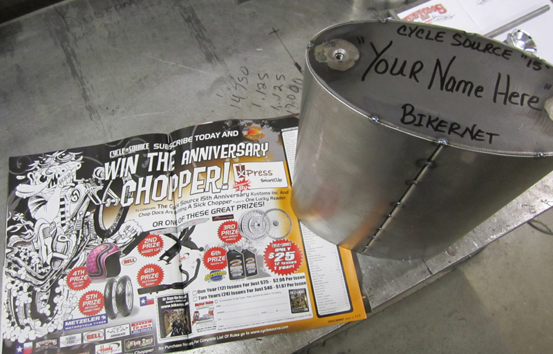
So Julie jumped at the chance to dig in on the first fabrication build project for the Bikernet/Cycle Source Sweepstakes build, the oil tank. Kustoms Inc. offers several hand-built oil bags. They manufacture a couple of sizes in a donut configuration, with a hole down the center. They also offer a couple of sizes in this oval shape. Julie cuts out the end plates and then forms the oblong, barrel-like exterior. Gary machined mounting bungs using stock Harley gas tank rubber mounts to fasten the oil bag to the frame securely.

Julie drilled the holes in the tank for mounting bungs and oil line fittings. Gary ran the feed line to one end, the return line at the other end, and the vent line near the filler cap. They also drilled and positioned the drain cap bung and the filler cap bung.
After building precision racecars for a couple of decades, fabricating custom motorcycles is all about fun. “At one time, I had to hide my motorcycles when the car guys showed up,” Gary said. “Now the car guys want a chopper to match their racecar.”

Sure, bikes have always been the bottom rung, low-class outlaws. It never changes.
Don’t miss the next episode. They bought a set of ’90s, 3.5 gallon, H-D fatbob gas tanks. Julie will form the pieces to eliminate the dash dish and make them pure flat-sided tanks. Gary will mount them on either side of the frame so the frame will be visible down the center.
“This bike will be built to ride, but look cool,” Gary said.
Don’t miss the next episode, or a chance to win this puppy.
Sources:

Xpress
http://mysmartcup.com/
Crazy Horse
http://www.crazyhorsemotorcycles.com/


Kustoms Inc.
KustomsInc@hotmail.com



Fab Kevin
http://www.fabkevin.com/home.htm
Evil Engineering
www.evil-engineering.com
D&D Exhaust
http://www.danddexhaust.com/
Wire Plus
http://www.wire-plus.com/
Barnett
Barnettclutches.com
Shorai Batteries
www.Shoraipower.com
Bell
www.moto@rcn.com


Mudflap Girl FXR, Part 5
By Robin Technologies |
Life is nuts, but we are scrambling on the Mudflap Girl FXRs, at least mine. Us old farts constantly have discussions about how unmotivated kids are. I want to work on my bike constantly. Every waking minute I’m thinking about it, about new ideas, innovations, and who I can reach out to for resources. My son just complains: “I’d have to drive over there…”

I constantly come up with Plan B, another connection, or build it myself. We crawled out of the Sunday sack at 6:00 a.m. to haul ass to the Long Beach Swap Meet, just to scour rows of vendors for parts, to find a handful of pieces, and we scored. If it wasn’t for the Sunday Post, I’d comb the isles once a month, at least.

Whatever, I’m about to wire and fire-up the first Mudflap Girl creation with Spitfire, H-D, and JIMS.
But let’s back up to installing the Trock-modified CV carburetor. I ran over to Branch O’Keefe next to Bennett’s Performance on Signal Hill to discuss an intake manifold. I don’t have anything against most dealers, but I like to work with the talented independent shops, owned by guys with history, who go the extra mile for performance, quality, and their customers.


I feel Bennett’s and Branch O’Keefe work hard to keep guys on the road, with high performance motorcycles. John O’Keefe dug around and came up with a very rare H.E.S./Branch Evo intake manifold. I helped Andy Hansen get Harley Engine Specialties off the ground in the ’70s. Andy passed, as did Trock a few years ago. He was a great guy with veins full of 60-weight. John told me he still has a few of these rare, tested, flowed performance intakes and wanted me to try one.


With John’s assistance, these guys are building hot rod twin cams with some very special confidential products. I’m hoping to bring you the story and access to some of these secret products in the near future. I mounted his intake with stock clamps.

After installing the rear wheel, we discovered the oil tank could not be installed from the front with the engine and trans in place, and we had to remove the rear wheel. It wouldn’t install from the rear without removal of the wind guard and one frame-mounted rubbermount. We made it work without removing the engine and trans.


At this point, we jumped around the bike looking for any project affording completion, without trips to suppliers, missing fasteners, or parts orders. We took a hard look at Spyke’s new BDL starter jackshaft fix. I’ve used BDL systems for ten years without a problem, and no starting hassles. It took us a while to understand this system. Basically, it allows the starter gear to bounce, not jam into the ring gear. Once we understood how the Spyke fix operated and the lack of spring travel in the BDL system, we came face to face with the benefits. We moved on to fitting the fender.


This tough 9-inch fender fit perfectly with some slight modification grinding on the Spitfire fender rail tabs, but the bottom front of the fender smacked the oil bag and prevented perfect alignment. With some heat and our shop press, we pushed a buffing groove in the fender. Then we cut the massive notch for the chain and the fender was getting damn close. Ray took up the grinding duties after I cut the notch with the plasma cutter.


Then we turned back to the oil bag, which we had grown nervous about some characteristics. This was a one-off, first attempt by the Spitfire motorcycle crew. They did a helluva job, but we noticed that the return and vent oil bungs were down the face of the bag, restricting oil capacity. We stopped by Gard Hollinger’s LA Chop Rods facility and asked for a couple of 1/8-inch pipe threaded bungs. Gard doesn’t manufacture that size, but he does make ¼-inch pipe thread bungs, which seemed foreign to me, but we stepped up.

This was a tough, and scary operation. I didn’t want to risk drilling and dropping metal shavings in the tank. Jim Murillo recently sealed the tanks and coated the interior. The alternative was a 2.2-quart oil bag over a 4-quart oil bag. We swallowed hard and started the operation of drilling the holes in the top of the tank. I turned the bungs down slightly so I didn’t have to drill ¾-inch holes in the tank.

Ah, but for every obstacle, there’s an opportunity. We discovered a perfect exterior clear oil gauge, fucking beautiful. We started to drill the holes in the top of the tank for the return lines.

We also had a squirrelly obstacle with the top motormount. The frame came with a chunk of tubing protruding directly down from the backbone under the tank. In the end of the tubing, the Spitfire crew welded a hearty bung, and it was drilled and tapped to 7/16 fine threads. I went on the hunt for some 7/16 hiem joints and McMaster Carr had a couple in stock. That was my initial direction, but it had its drawbacks.


I kept looking for alternatives and discovered a tab that was part of the Biker’s Choice top motormount kit. The slot in one end was 7/16-inch, and it pushed the hiem joint anchor spot out far enough for the pivot point to reach the stock hole in the top motormount. I went to work welding it, but Dr. Willie didn’t like my fix. I want to give it a shot.


We also ran into a return line problem with the stock Softail engine configuration. The return oil line from the filter pointed directly at the transmission. We straightened it and ran the line, then thought about running an oil filter. We went on a search for an old Cadillac power steering oil cooler. This turned into an afternoon excursion, hitting junkyards in our ghetto area and all the auto parts stores. At the last Auto Zone, we scored this Cadillac power steering oil cooler and made a mad dash back to the shop.


We considered running one of those front motor-mount regulator brackets, but I didn’t like the way it interfered with the mount and the engine fasteners. Since the frame was built perfectly for this application, we cut and fitted a chunk of rectangular tubing stock between the frame rails to house the Spyke regulator.

We drilled it, installed fasteners from the back, and welded them into place, forming studs on the front. It was good to go once we tacked it into the frame. This project has a devilish twist, since we plan to build it, then test ride for a month or two before a paintwork teardown. I’m not using nylock fasteners this time around, just lock washers. Some items will be TIG welded, whereas some will be MIG spot welded for the tryout period.

When I grappled with the Biker’s choice CV carb mounting system, including breathers, I discovered the Branch/H.E.S. intake difference. I was forced to slice and weld the bracket in an alternate position. That puppy will need to be ground and reshaped before powder coating. We moved ahead and I discovered my Goodsen Fantasy in Iron air cleaner was built for a Mikuni, so I traded with my son for his Roger Goldammer, hand-pounded, stainless steel unit.


What a sharp, well-thought-out chunk of artistic workmanship. Everything about his air cleaner was well configured, from the backing plate to the position of the fasteners. It came with all the necessary fasteners and two foam sock-like filter elements.

I have never liked the single bolt rear axle adjuster. It allowed the axle to float and shift from its required setting, which can be downright dangerous. I ordered some special fasteners and set to drilling and tapping the stern of the swingarm bosses. They were massive, solid chunks of Spitfire steel. It took some time, but now the axle is locked into position.

.jpg)
Then we started to grapple with the kickstand. The obvious choice was a weld-on unit from Mr. Lucky, but he didn’t have any in stock.

I needed to install the 3-inch BDL belt system, to see where the kickstand would hit. Some kickstands can be a bear to reach, or take up much needed ground clearance. The more I looked at the Spitfire forward controls, the more I didn’t want to mess with that area. The only kickstands available that might fit this configuration were pricey jobs, and I suspected they wouldn’t fit. I started to dig around.


This new BDL belt drive fell into place after I drove the pins into the engine pulley. The clutch slipped right into place, and then I carefully selected washers and shims behind the engine pulley until both pulleys were aligned.


This new system has just two big, tough, 3/8-inch stud fasteners and stand-offs. One has a step in it, and it took very little time to determine which position it was machined for. The rear stud hung over the ring gear and needed additional clearance, but I goofed. I used red Loctite on the stud, and I should’ve stuck with blue. I’ll have to remove the aluminum stud anytime I remove the clutch.


Then inspiration surfaced with the notion to run a rear kickstand. In searching my parts bins, I came across a wild kickstand base. Unlike the old ones from the ’30s to the ’70s, this one worked the same, but was heavy and cast. With Ray’s assistance, we came up with the materials and the notion to bolt it to the swingarm cap, which is held with two 7/16 fine bolts. I went to work while Ray peeled out for Cook’s Shootout in Bonneville.


I tacked and tested it until I was convinced I hadn’t completely fucked up. Then I cut off the tabs, and ground and shaped the massive chunk of steel. I TIG welded this puppy together, mounted it, and made a cool stop threaded into the frame.

Next, I’ll start wiring with Wire Plus products and the bike should run within a week or two. Then it’s off to Saddlemen for a seat. Hang on, the Mudflap Girl will live.

But wait, I forgot that we installed the Spyke Push-Button solenoid starter. It eliminates weak connections, starter relays, and starter button wiring. It’s a breeze to install, but it’s important to make sure, once the button is released, it’s fully clear of contact.


Sources:
Spitfire
Biker’s Choice
JIMS Machine
MetalSport
BDL/GMA
Wire Plus
Branch O’Keefe
Bennett’s Performance
Custom Cycle Engineering
Mudflap Girl FXRs, Part 6 Wiring with Wire Plus
By Robin Technologies |

Wiring is always a treat, unless you use one of those systems in a box like Phil’s speed shop systems. I ran one on my factory racer, and it was a breeze. I’ll try to find a photo. It was designed to mount to the frame seat post. Inside it contained the circuit breaker, the starter relay, the ignition switch, the starter button, high low beam, and horn button. Then a ream of wire rumbled out of a hole. I guided them to the appropriate spots and hook them up. Nothing to it.

In this case, we worked with Wire Plus since they are the masters of wiring kits, Speedos and assorted equipment. They sent me a complete wiring harness with a starter relay, flasher system for turn signals, a 30-amp circuit breaker with mounting strap and rivets. They also included an installation and operator manual for model Wp192, Mid Frame Mount System, with Chopper style harness, with or without turns.

Their manual affords the reader a lighting circuit flow chart, an ignition flow chart, and an accessory flow chart. It demonstrates several ignition switch wiring circuits and handlebar circuits. It even comes with a Wp143 lighting control system for auto-canceling style harness. Actually, I checked the Wire Plus web site and they do make a seat post ignition switch wiring system unit, in a coffin shape, classic, and old school. They also make a cylindrical shaped engine mounted ignition switch housing, and ignition and toggle switches. They have systems that include compression releases–Amazing.

Wire Plus also makes individual wiring products, like their lighting control modules, power modules, plus custom power ports, for plugging in accessories. There’s a reason for going on and on about Wire Plus. Wiring can be a nightmare, and I’m a lazy. I want to be as minimal as possible, for ease and reliability, but I’m fulla shit. Just about the time I think I need to cut turn signals out of my system, someone is wiring in heated grips, or a heated seat, a some sound system, or neon lights under the engine. I avoid anything extra, like the plague. Hell, wire plus make engine mounted electrical port systems, so you can plug in your heated vest, helmet sound system, or whatever.

This is going to be a terrific test. My son’s bike will contain more bells and whistles, and Grip Ace controls in the bars. Tim from Grip Ace from Rivera is coming over to show us how easy it is. On Frank’s bike, we will install turn signals, so anything is possible. We will also wire a metric bike, the XS Yamaha bobber. So, over the next couple of months you will witness three variations, with Wire Plus products.


I start wiring by finding all the components and placing them somewhat in position. Then I search for a place to hide the circuit breaker and a circuit board, or bank of connections. First, we made a trip to the local Marine store and ordered an ignition switch. This included a starter switch, but we were using the Spyke push-button starter mounted to the solenoid. It eliminated the starter relay and any starter switches.

Once I determined a handy location behind one of the Mudfap Girl FXR panels, I drew up a wiring schematic, while referring to the Wire Plus handy manual for guidance. I came up with this nuts notion of hiding the ignition switch under the seat nose, which would position it perfectly for some of the wiring, and run some of it through the backbone of the frame. I grappled with a mounting notion, but Danny came up with the final notion, which took a lot of work, but was highly secure.


Wire plus makes several digital speedos, and several mounting systems for different applications. It was a breeze to mount and wire once I found the mysterious neutral switch connectors, which I ordered from the factory. The WP speedo mounted like a dream on the bars, once I plugged the wiring harness into the rear of the unit, ran the wires under the tank, back to the nerve center for power, then to the speedo sensor, and the neutral switch. Nothing to that one, although I wouldn’t mind running the wire loom through the frame in the future.


Since I was thinking about the rear brake pressure switch, I started to work out my GMA brake systems, and we made some measurements. I ran over to Baker Performance products and in five minutes we had new brake lines cut to size. This was probably the easiest bleeding process I have ever encountered. They were bled and working in no-time. Unfortunately, GMA doesn’t make a clutch lever to match.


On rubber-mounted bikes, I run two grounds. I welded one to the frame and I use one of the Spyke starter mounting bolts as an auxiliary ground. I don’t want to take any chances with the charging system, or the ignition system missing a grounding connection.


I needed to mount an On-On switch in the headlight bucket. It took some hunting for the correct sized switch, then a headlight seal beam from Biker’s Choice, and a lot of digging for a three blade connector. My headlight came from a spot on a police car in the ’30s.


Almost all of my electrical components came from Spyke or Compu-Fire. The Compu-fire ignition system is a breeze. This time I’m running a Compu-Fire single fire ignition system, with their single, dual wound coil, which mounts between the heads, in the standard stock position. It’s all too tight and convenient. Two wires to the coil and one to power and the system is good to go. It’s about that easy to time.

My son showed up with the missing parts for his Bub Bare exhaust system, and we started mounting it. I wish the exhaust guys would make kits with the flanges and retainer spring rings. Some systems come complete, but it’s a drag to run to the dealership, when you’re ready to rock. I understand why they don’t supply them with many system. If the system is replacing a stock system, we just switch out the parts. And these four pieces would jack up the price, but give the customer the option, and the manufacturer could make an extra buck and save the builder time and hassle.


This system slices damn close to $350 and you paint it with whatever heat paint, or heat wrap you like. It’s very similar to my D&D system.


Sources:
Spitfire
Biker’s Choice
JIMS Machine
MetalSport
BDL/GMA
Wire Plus
Branch O’Keefe
Bennett’s Performance
Custom Cycle Engineering
Saddlemen
Bub

The Magnificent 5-Ball Factory Racer Featured
By Robin Technologies |
.jpg)
Editor’s Note: Our 5-Ball factory racer was feature in Heavy Duty Magazine in Australia recently. It’s the largest selling custom bike mag Down Under. The story and the photos were handled by the amazing Smilin’ Doc Robinson, the longtime tech editor. I’ve left the story alone for your viewing pleasure. Enjoy.–Bandit
Many interesting and colourful characters populate the biker world and Keith “Bandit” Ball walks tall among them. And not only because he tops out at six-foot five inches. Lifetime biker, author, longtime Easyriders’ editor, custom bike builder, salt racer, founder of the premier web site Bikernet.com, Bandit is all this and more.
Get him settled in the comfortable lounge seat in his Los Angeles abode, pour him a stiff whisky, and sit back as he shares tales of the road, some that would make your hair curl, others that are genuinely side-splitting and always among them, lessons to be learned about life.
I figured that the best way to introduce this build to HEAVY DUTY readers is to give it to you in Bandit’s own words: “For decades guys have built vintage- looking scooters with late model drive-trains. Hell, I built another one at Strokers Dallas in the ’90s. Before I dreamed of it, Arlen Ness built a ’20s vintage scooter and sidecar around a Sportster engine.
Randy Simpson built vintage kit bikes. Don Hotop built some of the finest vintage-styled customs and recently I saw a ’20s styled bike at the SEMA show in Las Vegas built by the Shadley Brothers for House of Kolors. Beautiful piece. So I ain’t the first by a long shot. But there is something in the air recently about respecting the old iron and bringing it back to life. Some of it has to do with restrictions, and building older bikes is unrestricted. Some of it has to do with nostalgia and some is just a wild departure from the last project. I’m excited every year about this learning process.”
I asked Keith to sum up the vision that drove this build: “Well I built it in the teens vintage style, but with my height and long limbs I had to scale it up a bit. It’s built for long miles, with floorboards, a sprung seat, rubber grips, tall gearing and a spare gas tank. Every custom motorcycle build is an adventure. It takes me from one crazed time in my wild life to another. Fortunately, I’m not spilling my guts about another woman I lost during a knuckle-busting build. But this build did represent turning points. I’m rapidly closing in on my mid-sixties and about ready to sign up for Social Security. It also represented our stinky economy.”
Bandit is such an industry icon and it is not surprising that many of the leading lights of the motorcycle aftermarket were involved in this build, blokes like Ron Paugh of Paughco, leading manufacturer of custom parts and accessories for the past forty-three years, Rick Krost of US Choppers, Chica, who needs no introduction, Gard Hollinger of LA Choprods and HEAVY DUTY photographer Glenn Priddle who made the sweet seat.
Here’s Bandit again: “The key to the success of this project is the drive train. I sought a Crazy Horse V-Plus, 100-inch engine for several reasons. It has a classic design, renewed performance, cool looks and a left-side carb. I coupled it to a JIMS 5-speed transmission with a Baker kicker unit and Baker N1 shifting drum, so I can run the tank shifter and find neutral without a problem. The rocker clutch system I put together from old H-D parts while I fabricated the tank shifter.”
When he hasn’t got a fast motorcycle between his legs, or a whiskey in one hand and a beautiful redhead in the other, Bandit is happiest welding, soldering, wrenching, milling and turning metal in his secret and damn well-equipped lair beneath Bikernet HQ. His other love is writing, usually upstairs in his 1923 shop, behind his glass-topped Panhead-motor desk, rattling his computer keyboard, churning out another fiction book, a book for motorbooks, magazine articles (sometimes for HEAVY DUTY), or news, or one of dozens of tech articles for Bikernet.com.
And for those of you who are truly interested in the real guts of bike building, let me recommend reading the whole story of this build on the Bikernet.com web site. It runs over some eleven parts and is well illustrated with photographs showing each and every step of this build.
If you only read one part of the full story, make it Part 6 where you’ll see the immense amount of work that went into the rear fender fully detailed as master metal shaper Chica gets to work. But once again, I strongly recommend you read the whole thing as a salutary lesson on just what goes into a ground up build. Without the space limitations of a magazine Bandit is able to show and tell stuff that you won’t find elsewhere. To find it, go to Bikernet.com and click the Free Departments button and select Techs and Bike Builds and scroll backward through the various articles until you find Part One and take it from there.
I really dig this bike in every aspect; the concept of honouring old iron in this way, the marriage of old school looks with a nod here and there to practicality and safety, given that brakes back in the first two decades of the twentieth century were mighty primitive to say the least. I love that shifter in all its brassy mechanical glory, the vintage touches like the chain oilers and the leather strap holding down the battery and the cool fuel tank mounted up top to extend the bike’s range.

Having examined it closely, both during construction and in its completed state, I can attest that the fit and finish all over is excellent and detail touches like the pin striping are icing on the cake. Keith thanks Sin Wu for her part in this build and reckons this woman is a keeper, and I can understand that. This bike is a beauty and will look just as cool in fifty years from now. Way to go Bandit, I’ve seen several of your other builds but with this one you’ve climbed a pinnacle. HEAVY DUTY is proud to feature it in our pages.

BIKERNET EXTREME GUTS&BOLTS TECH CHART
ENGINE
Type: Crazy Horse Power Plus 100
Capacity: 100ci
Cases: Stock
Crank Stock
Bore: 3.874″
Stroke: 4.25c
Heads: Stock
Ignition: Thunderheart
Carburetion: S&S Super E
Manifold: Stock
Air cleaner: powder coated by Worco
Exhaust: Bandit built
Muffler: Stainless Scorpion from John Reed
Estimated power: 80hp
TRANSMISSION
Year: 2006
Type: JIMS
Number of gears: 5
Gearchange: Bandit built
Baker N1 Shift Drum
Clutch: BDL
Primary drive: BDL Classic powder coated by Worco
Rear Drive: Exile chain
SUSPENSION
Front: Paughco narrow tapered leg springer
Triple Trees: steel from Paughco
Mods: 2″ under length
Rear: Rigid U.S. Chopper design
WHEELS
Front: Black Bike dimpled 23″
Tyre: Avon
Brake calipers: GMA by BDL
Brake rotor: H-D
Brake lines: John Reed
Rear: Black Bike dimpled 23″
Tyre: Avon
Brake caliper: Exile
Brake rotor: Exile Sprotor
FRAME
Type: US Choppers vintage rigid
Make: Factory Racer by Paugho
Year: 2009
Rake: 30 degrees
Seat: Glenn Priddle
CONTROLS
Handlebars: Narrowed Flanders
Grips/levers: H-D, BDL/GMA
Risers: DPPB bronze dogbones
Master cylinder: GMA front
Mirror: Lowbrow
Headlight: pinstriped by George the Wild Brush
Footpegs/forward controls: Paughco vintage footboards
Rear brake master cylinder: H-D
Speedo/tacho/oil pressure: Biker’s Choice Vintage Sportster
Taillight: powder coated by Worco
Other modifications: rocker clutch system made with old H-D parts, Phil’s Speed Shop wiring harness and ignition system, alternator charging system by Spyke
GUARDS/TINWORK
Front guard: missing
Rear guard: Chica
Fuel tank: Paughco
Trim: gone
Oil tank: Paughco
Other modifications: Vintage H-D tool box and brake linkage by Paughco, Reserve gas tank by Mike Pullin
COMMENTS: This bike was built in the teens vintage style, but built for long miles with footboards, sprung seat, rubber grips, tall gearing, and spare gas tank. The plan was to ride to Sturgis, but I never got out of Dodge. Now the plan is to ride it to Arizona for the too broke for Sturgis run to Salome, a little sun burnt town in the middle of nowhere. But it has a very cool or western saloon on the edge of town.
Partners in Crime:

Mudflap Girl FXRs, Part 8 Wiring World
By Robin Technologies |

Since last time, my Mudflap Girl is still over at Saddlemens waiting on a custom seat, but good news filtered into the shop this week. Next week, we should move forward.
Then my son made his dire announcement: “I wanted forward controls,” he said. “It’s all your fault. I agree with Jesse James, you’re nothing but trouble.”

I struggled with the assembly of his mid controls for months. I kicked the Handy steel lift and stubbed my big toe, knowing full well I stood on the right side of the law, and my son was out to lunch on this issue. But as the dad in this scenario, I should be the bigger man. Besides, mid controls can be a puzzling pain in the ass. I dug through my lockers of old parts and found enough components to make up the shift side of forward controls, but I didn’t have the rear brake master cylinder, or the lever and plate. I kept digging.

I reached out to Paul Cavallo, the boss of Spitfire Components, and our Mud Flap Girl frame builders. I thought if I could order a set of the weld-on ½-inch forward frame mounts, I would find the remaining billet aluminum controls parts at the Long Beach swap meet.

Here are some thoughts when it comes to mid controls versus forward controls: Mid controls tighten the looks of the drive train, but make it harder to work on your primary, clutch, oil pump, engine and pipes. They can be a tight, cumbersome addition. On the other side of the coin, they enhance the appearance of any bike by allowing the frame to slither unencumbered until it fades under the engine. And from a handling perspective, mid controls can actually lesson the weight on the lower back.

Okay, so forward controls are sort of out of the way of the engine, the pipes, and the primary. They are easier to install and adjust for long-legged bastards. So what the hell; we started to shift gears. Paul Cavallo assured us of a new shipment of their super-simple to install and bleed forward controls, so we stepped up.

Oh, regarding Jesse James. He complained to the publisher of Heavy Duty Magazine, in Australia, when I didn’t vote for him during the big American Chopper Build-off, in Vegas a couple of months ago. A year ago Heavy Duty asked me to fill in for Jesse, since he was acting up, so I started writing a column for the largest Harley mag in Australia. But now I’ve been fired, because Jesse threatened the publisher, “It’s either him or me.”

In the meantime back at the Mudflap girl, I grappled with the electrics. I had a few issues to mess with. I planned to install a Wire Plus speedo-dash to Frank’s Spitfire T-bars. Grip Ace would handle switches with their electronic module, and the ignition was a Crane Hi-4, a versatile unit. The Hi-4 can be set up to fire a single-fire system, dual-fire, dual plugs, tach, VOES, you name it. I also had a Wire Plus wiring system as backup. It contained the starter relay, blinker relay, and wiring schematic.

A quick sidebar: We built this belt guard out of solid steel rod and strap. I’m a stickler for strength. I like looks, but strength is everything. I would rather the rear strap was 1/16-inch thicker. I will keep an eye on this puppy during the break-in period. Swingarms are bastards for abuse; that’s why mounting fenders to swingarms is particularly tough. Every bump, vibration, or shock a tire endures is transferred to the swingarm, and anything attached to it. Unlike a rigid frame, a swingarm is designed to move rapidly to cushion the ride.

I dug around and found an old ignition switch with an old worn brass key. I looked for a thick washer with the same I.D. as the switch’s O.D. and welded it to the top motor mount. Seems a very accessible position for a switch, and close to the coil and ignition system wires.

At first, I thought about running a circuit breaker on the other side of the motormount, and installed one. As it turned out, I never ran a wire to it, so I removed it.

Since S&S took over the classic Crane Performance products line, we had access to Crane products. My son’s performance aspects will all be Crane and S&S, including the E-carb, a Crane cam, adjustable pushrods, etc. First, I installed the Crane sparkplug wires. This is one damn thing I take my time with. It’s too easy to cut a wire short. I find the kits often lacking the proper pieces, or pieces too tough or tight to install without going nuts. It’s good to collect spare parts. Don’t throw anything away, goddamnit.


For instance, this kit comes with the sparkplug end of the wire already fastened to the cup and lead. I couldn’t find a brass fitting for the straight-in coil sleeve end, but I had some in another kit. I followed the directions and greased the inside of the rubber boot before I started. With the wire and the boot greased, I slid the boot past its position, carefully cut the insulation back about ¾ of an inch, and then folded the carbon lead over the insulation. I carefully crimped the brass fitting into place using several different configurations of pliers, since I don’t have any special tool for this operation. Notice how the brass must bite into the plug wire insulation.

It’s a delicate, tough operation, but once the boot is pulled into place, the tight rubber will hold the fastener and the wire firmly. My son, Frank, the tattoo artist, stopped over and we handled mounting the controls on the bars. These controls were designed for stock application, and we would not use the stock switch housings, because we were dedicated to using the new Grip Ace system due to its simplicity, but we’ll get into that later in this chapter.


We installed the modified handlebar controls with some 1-inch Dewey wheel spacers to make up for the missing bulky switch housings. We were installing the Biker’s Choice Motion Pro clutch cable when Erik Lundmark, from Lundmark Studios, popped in and started filming us for his new TV series, Kustomz. It’s so long between shoots, I forget about the creative effort, but it may pop onto a cable channel near you someday soon.


This build is interesting, because it forced me to go in different directions and away from another rigid frame. In fact, some readers applauded the variation from rigids to something more long-road worthy, and the FXR platform was perfect. I’m beginning to understand why some builders always use the same tried and true components over and over. I can use the same parts, and they fit the same way as the last build, with no surprises. Since Ben Kudon at Rivera asked me to try their new belt system designed for use in a stock primary, I agreed to try it. No big deal, right? The bike was built in 1996, and we stumbled across a set of 1989 primaries.


As it turned out, the starter jackshaft in the early primary was much larger in diameter than late model units, with less pinion gear teeth, but much larger. Consequently, the Spyke starter wouldn’t work and I had to return it. Then the jackshaft was all wrong, and finally, the ring gear on the Rivera Primo Inc. clutch was wrong. Ben sent me another ring gear and it wouldn’t fit on the Rivera clutch shell. He thought I had a stock clutch. What a minute; I was building this with a primary, primarily to use their new system. Switching ring gears was not fun, due to their red Loctite-coated fasteners, and we had to drill out several locked-down Allens. Fortunately, Rivera-Primo makes ring gears for almost any application, so I was covered.


Ray C. Wheeler and I tried everything, including WD-40 and stronger penetrating lubricants. Ultimately, we rounded Allen wrenches, drilled out a few, and used easy-outs. Then the clutch rolled back into shape with the new Spyke starter and jackshaft assembly, but we were missing one dinky element. That surprise came later.

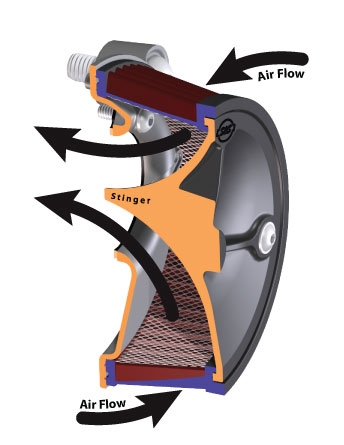
Next, we started to wrap up the carburetor install with the new S&S Stealth Air Cleaner design. Here’s what the gang at S&S said about this system: Everybody likes to go fast, but not everybody likes to advertise. The S&S Stealth air cleaner kits are for the rider who likes to go fast, but wants to be just a little bit sneaky. Get all the performance of the S&S design, including the air directional “stinger” cone in the filter, and hide it under your stock Harley-Davidson air cleaner cover.

Owners of 1999–2012 Harley-Davidson big twins can install the new S&S Stealth air cleaner kit and pick up more power, using their stock air cleaner cover. Nobody will know because it looks entirely stock. We’re talking sleeper hog!


Owners of 1993–1999 big twins with Evolution engines and owners of Sportster models can get the same performance kick, but won’t be able to use their stock covers.


We didn’t want to use a stock cover or be stealthy about it. S&S makes a series of their own aluminum cover designs, but we gave it the Mudflap Girl touch from 2Wheelers just before they packed up and rolled out from Denver, heading east for Daytona Bike Week. I liked this new system a lot, from the lightness of the components to the auto-venting system built into the bracket. No tubes or hoses needed. This installation was a breeze.

Something sneaky slithered around the shop about the time a cold chill slipped over the LA basin. I discovered how aerodynamic Frank’s Spitfire tank was and how well it fit on our Bonne Belle 45 being built for Bonneville this year. I stole the sleek tank off Frank’s bike and mounted it to the 45 Paughco frame. It fit like a glove. I ordered a 3.8-gallon tank from Paughco, and it arrived just after the winter show series. Ray helped me grind off the rubber-mounting tabs.


I started the wiring process, knowing full well the tank would arrive any day, and I would need to reroute some of the wires. I stuck the Grip Ace wiring module in the backbone of the frame, installed the Grip Ace grip, and tried like hell to find quiet, unencumbered time in the shop alone to perform wiring magic. It’s not difficult, but it takes quiet thought, testing, wire running, wire accounting, and figuring.

It’s too easy to run a wire, and then discover another wire needs to follow the same path, such as the neutral switch wires running off the transmission. That wire (one is a ground wire) can run up to the Wire Plus speedo, but the oil pressure switch will follow the same route, as will the speedo pick-up, the wire to the starter solenoid, and maybe the wire to the brake light switch.


I’m using the longer spin-on oil filter to hold the alternator/Spyke regulator plug in place and give the bike more oil capacity. We used the new JIMS tool to pull the filter, and we replaced it by hand. I mistakenly thought I could wire this bike without a circuit board, but quickly shifted gears after I made a small bracket to hold the 30-amp circuit breaker under the seat. Then I welded a small mounting plate to the bracket for the board, and everything started to fall into place. I found some quiet time and started running wires. When I first wire any bike, I draw a schematic with the basic components and start an initial map. It’s a damn good idea, because it’s super easy to forget one item, like the flasher unit for the turn signals.

I also grappled with the VOES switch. I reached out to Bruce Tessmer from S&S for input. I’ve run maybe one VOES switch in my building career, so I didn’t see any reason to go there. Bruce explained the reason behind the switch running off a vacuum tube from the carb. It is designed to help prevent pinging in high performance engines when they don’t have access to high-octane fuels, or run in high altitudes. Since we don’t generally encounter those problems, and we are running near-stock compression engines, I ducked that aspect, and wired the Hi-4 system into place.


My grandson, Frank Jr., recently took over the XS build, and he rolls over to the headquarters on a weekly basis. He’s a worker, willing to sweep the floors, turn wrenches, anything to assist in the process. He’s turned into a major asset around the shop, and has recently become the designated rider for 45 Bonne Belle, since our Australian female tattoo artist had to bow out for this year. Frankie, 18, is also a tattoo artist in the making. We dove into re-installing his XS engine into the Mr. Lucky, Paughco-built frame, and Frankie is now helping with the Bonne Bell build.


Next, we will fire Frank’s FXR, check the wiring, adjust the carb, and we will both be in the market for seats. Mine is scheduled to come from Saddlemen and Frank’s from Le Pera. Hang on. Oh, and we’ll come face-to-face with our jackshaft learning curve. I’m getting anxious to ride. I’m scheduled to meet the Saddlemen crew in two days.

Spitfire
Biker’s Choice
JIMS Machine
MetalSport
BDL/GMA
Wire Plus
Branch O’Keefe
Bennett’s Performance
Custom Cycle Engineering
Saddlemen
Bub


Saddleman Improves the Amazing Shrunken FXR
By Robin Technologies |

SADDLEMEN MODS TO THE SHRUNKEN FXR–In a world where over promising and under delivering has become all too common here is a gem I must share. The Bikernet built Shrunken FXR has become my daily rider and needed a couple small adjustments to be just perfect for me.
One detail was the too small seat or the bike was too fast (pick one). So I rode my bike over to meet the nice folks at Saddlemen and see what they could do to help me out with my seat. Upon arriving at the Saddlemen facility I spent time with guys from the front office to the guys in the shop ( all of whom took great interest in my motorcycle and the seat they were going to design and build). I noticed from the get-go these people were all riders. I shouldn’t be impressed by that, but there are so many folks in this industry who don’t even ride anymore.
We discussed what I needed (lumbar support) and a lip on the edge of the seat to keep me from being bucked off or sliding onto the rear fender. We also discussed the lines of the bike and that in the case of the Shrunken FXR , less was more. After the team and I spent a great deal of time figuring out what we wanted and didn’t want I was able to walk around the shop and see the whole seat making process from start to finish. man was I impressed!
So many talented folks all working together to put out an amazing array of products designed by and for riders! It was a real treat to see this and made me truly appreciate what they do much more. Great companies, in my opinion, are made of the people who work for them. So I left my bike for mock-up, and received a call back in a week.

When I showed up I saw the foam of the seat had been formed and pan had been constructed. We discussed coverings and stitching, again less is more. They got it and even pointed out to me the lines of the bike would be reflected in the seat.

Three days later I returned to pick up my bike and see my new seat! A seat is the finishing functioning touch to any motorcycle (much more than something you sit on) it must reflect the bike while being comfortable and a key suspension element.

I was so happy to see the seat. It looked amazing and really I could not have imagined it any better than they had built it. I put my helmet on, thanked them and jumped on the bike to ride away. First thing I noticed was the lumbar support made the bike so much more comfortable to ride and kept me in the perfect position to reach all my controls.
The biggest difference was when I hit a huge pot hole (tons of em’ in area) was my ass stayed firmly planted in the seat and the impact was minimal. The seat made my bike complete.
Can’t say enough about how impressed I was with the Saddlemen crew and facility, in short they made my custom bike have a perfectly functional and stylish seat. The perfect blend of function and form. I suggest anyone who needs a seat built or customized give them a call. They are a family team of bikers designing and building products for bikers. I like it!
–Buster
Road King 12/20/02
By Robin Technologies |
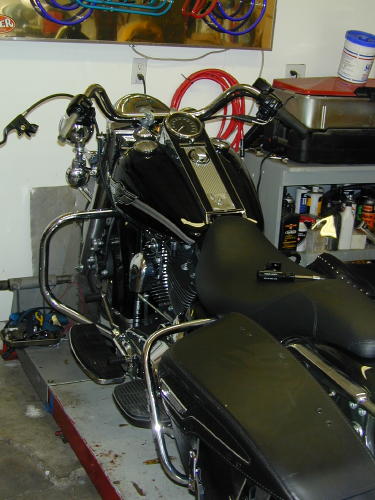

There’s an unwritten rule in the Code OfChrome that says, if you slip a set of highbarson any motorcycle you save it from mediocrity.There’s more, an evil punishment for this oftenillegal gesture towards the rebellious arts. Assoon as the unsuspecting rider throws his legover the saddle and reaches for the tall grips,his sideburns expand down the sides of hisface and a goatee springs forth from his chin.The cuffs of his t-shirt roll, and he begins tosmoke a pack a day. An treacherous grinspreads across his smoke tainted teeth, as ifa deadly rash, and before the week is out he’sleft his lovely religious wife and ravagedseveral other women. Hearts lie broken in histire-burned path. It’s an ugly sight. So what didwe do to the King next–Highbars to the stars.
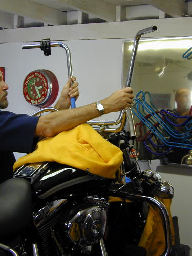
As soon as a date was set for theArizona Run I called Frank Kaisler, “We’ve gottwo weeks. Let’s install the highbars.”
“You’re nuts,” Franks said, “but we allknew that. Let’s do it. Make sure you have aroll of thin 60/40 solder, soldering paste and awide variety of long shrink tubing from 1/8 to1/2 inch. Oh, and you can get a head start bydrilling holes in the bars for the wiring and aslot at the bottom for the wires to exit. Startsmall and work up to and beyond 1/2-inchholes.
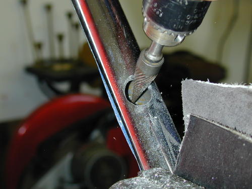
With multiple drill sizes and burr bits Iformed over 1/2-inch holes after holding thebars up to the bike and trying to estimate theposition of the grips. This is critical. I unboltedthe grips and measured the distance in fromthe end of the bars where the wires would runand noted the position of the wiring.
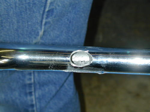
This was nervous work since it was notprecise. Even the slot at the bottom of thebars almost 2 inches long and 5/8-inch widehad to be carefully positioned not to put unduestress on the wires.
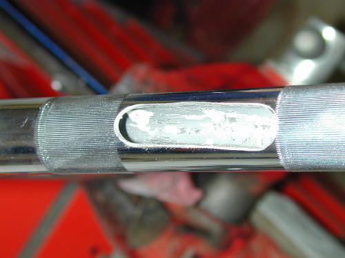
I took the riser housing off so I could seehow the wire looms and cables ran. WhenFrank arrived he brought along a sack full oftools that included emery bits and a dremeltool to smooth out the sharp edges particularlyon the inside.
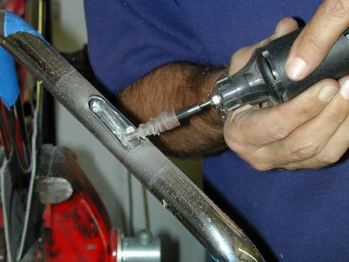
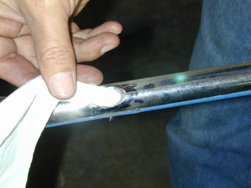
We quickly rounded out the edges of theholes so as not to cut the wiring. Frank usedhis trick of shoving a tissue paper in each holeto test for sharp edges or burrs. If it snaggedthe least amount we continued theedge-softening procedure. He also kicked meduring the process and reminded me todisconnect the battery.
Next we had to carefully strip theheadlighthousing and handlebars. To remove the riserhousing there are two screws adjacent to theignition switch (pop off the guide ring aroundthe ignition switch with a screwdriver), but thatdoesn’t do the entirejob. The headlight ring must be removed.Take the sheetmetal screw out of the bottomof the ring and then lift out and up. Thering is held by a notch at the top andsupported by a spring that will snap loose.When it pops free there are eight small blackscrews holding the headlight assembly inplace (the other silver screws are there toadjust the lens–don’t mess with them). Afterthey were removed theassembly came out easily but needed to beunplugged from the wire connection at therear.
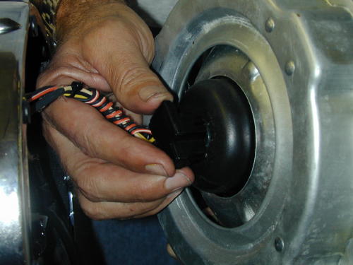
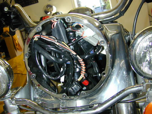
The wiring seems daunting, but it’s notbad and very organized.
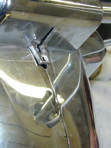
The last small bolt holding the risercover inplace goes in this hole under the nacelle strip.The strip hooks into the slot above it.
Then you need to reach up under thecowling and feel along the bottom for the verysmall nut that holds the bezel strip in place.Once the strip is removed, the riser cover canbe removed.
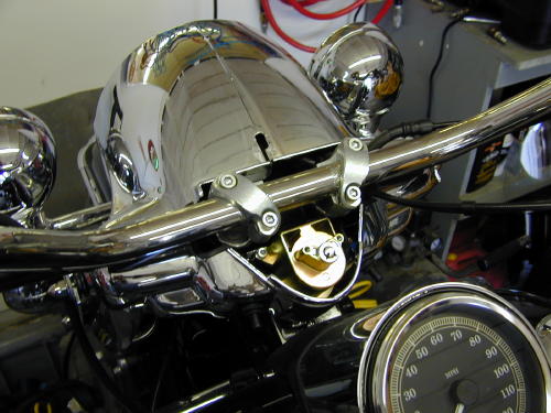
Here’s the cover removed. A lot of workto reach the handlebar clamps.
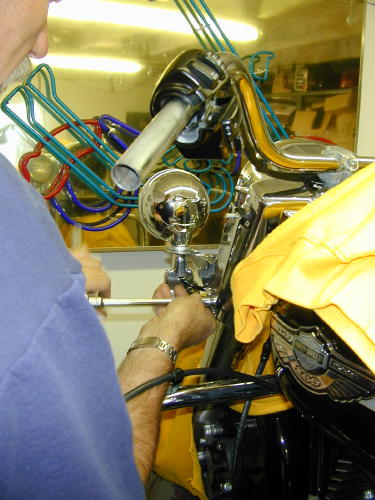
The two 5/16 dome nuts holding eachside of the bezel also hold the runners for thewindshield and the passing light bar, whichwe removed along with the front crash bar–Living dangerously.
Then the passing and turn signal light barwas removed for ever more, and the bezelremoved with the 5/16-inch dome nuts oneither side of the front end (make sure youkeep all the fasteners together including thewindshield runners). Set the chromed bezelaside somewhere out of harms way. That’s abig chunk of visible chrome.
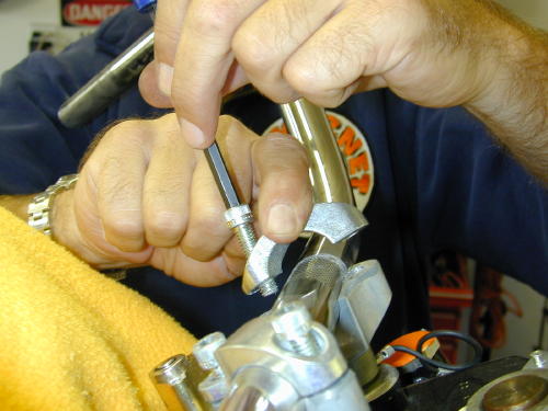
This photo reveals a handlebar clampbeing removed. It’s bullshit. We didn’t removethe handlebars until much later.
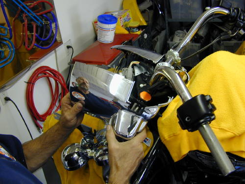
If you have a pal in the garage drinkingbeer and watching, get him to take shots ofthis process. If you must wait a week tore-install all this crap you may need areference guide and photos help a feeblememory. Or, of course, come to Bikernet andprint out this tech. Don’t forget to cover the tankand fender with something soft to protect themfrom scratches.
We noted that the electrical plugs on theleftside of the bike were different color from theright. We also noted their location and thedistance from the bars were measured beforeunplugging each connection to the handlebarswitches.
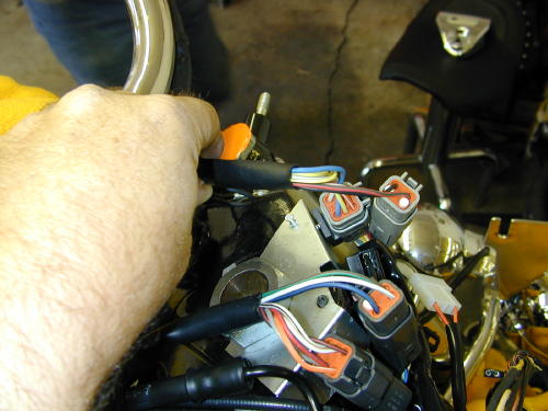
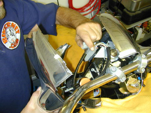
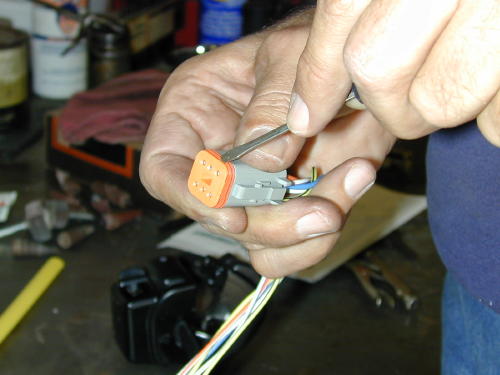
Don’t remove any wires before youdraw the diagram below. This cap performs acouple of functions. It seals the plug andinternally is pinches each wire lug in place.Once it’s removed a small screwdrive will pulleach catch away from each individual wire lugso it can be removed easily.
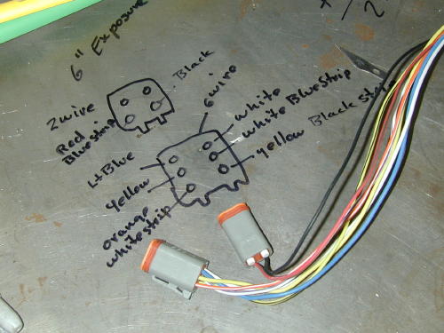
Check your diagram twice, no threetimes, before removing any wires.
We also noted the position of the throttlecables before removing the bars. Then thegrips were removed and switch housingsloosened so we could begin on the left side ofthe bars.
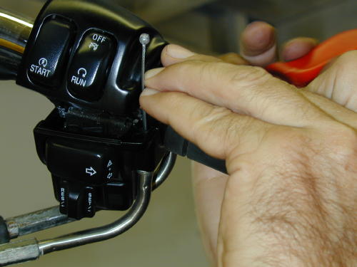
We handled the left wiring extensionfirst. This shot is of the right side and doesn’tshow a helluva lot, but it’s important. Toremove the throttle cable housings from thethrottle body it takes four miniature hands andtwo dinky screwdrivers to pinch the spring ringthat holds the cable in place. Be patient.
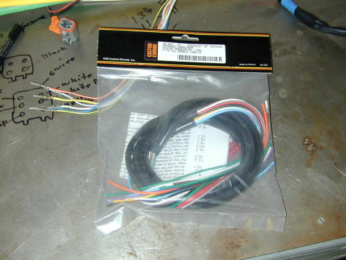
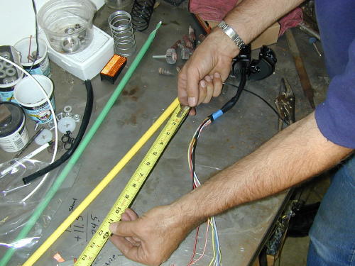
We measured the length of the wiresfromthe switches to the plugs, then compared thatmeasurement to the new highbars anddetermined that we needed to extend thewiring 13 inches to insure the proper length.Add an inch just for safe keeping. This aspectwas measured carefully several times.

Then the left switch loom was attackedfirst by drawing the back of the plug on thestainless bench top with a felt pen. We notedeach color coded wire and position beforeremoving the wires from the plugs. Do it fromthe back so you’re in the same position whenyou reinstall the wires.
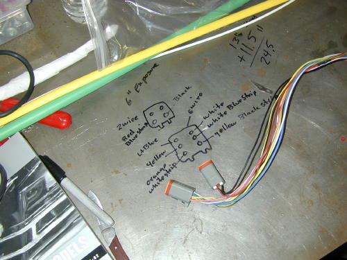
Sure, here’s another shot of a diagram,but it’s damn critical to insure the wiring iscorrect, so pay attention. Note, that we madeindications on the drawing to indicate the topfrom the bottom of the plug.
We added sections of 13-inch wirestaggered in the center of the loom so as notto stack junctions, and so we maintained theoriginal color coding. Each junction wascarefully striped 1/4-inch, soldered and sealedwith shrink wrap.
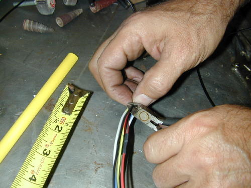
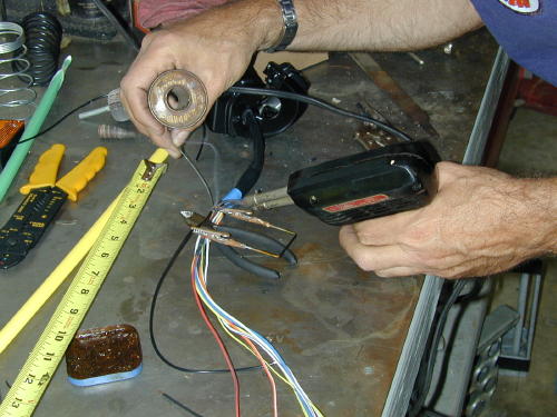
One shot we missed depicted thewires staggered. That’s also crucial so youdon’t have junctions bunched together.
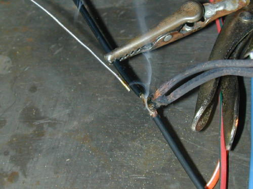
Note the handy wire connection holdingtool that Frank had made while working alonein his garage for ten years. Trying to hold theconnection together, while holding the solderand the gun is nearly impossible.
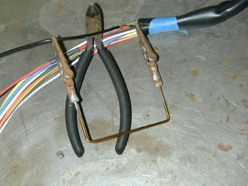
The Frank Kaisler, patent pending, wirejunction tool. Send $99.99 to P.O. Box 666,Hollywood, Calif. Send only rolls ofquarters.
He spoke to an engineer at one point whodidn’t cotton to twisting wires. He suggestedthat the wires be carefully mated straight onand soldered. The “Puerto Rican shrink wrap”as Frank refered to my colorful array of shrinktubing, was cut so that it would seal 3/8s of aninch on either side of the connection. Mostchunks of 1/8-inch diameter shrink wrap werea pinch over an inch long.
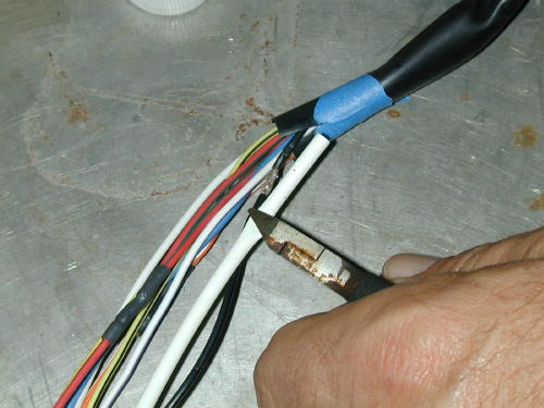
We also washed each connection withalcohol to remove the flux, which could harmthe wires or insulation, then with wet and drysandpaper, brushed any sharp edges thatmight cut through the shrink wrap.
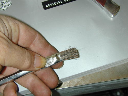
We cleaned the connections usingalcohol with this brush trimmed in half tomake the bristles stronger.
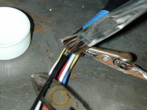
After each wire was carefully soldered andprepped we covered it with shrink wrap, thenusing Frank’s handy tool we heated the areaand moved onto the next stage.
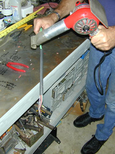
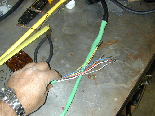
Then the looms were carefully coveredwithadditional 1/2-inch shrink wrap. Finally thebars were carefully blown out with the aircompressor and wiped clean before thelooms were fed into the grip ends of the bars(first we wrapped the pin connections withpainter’s masking tape and created a guidingpoint).
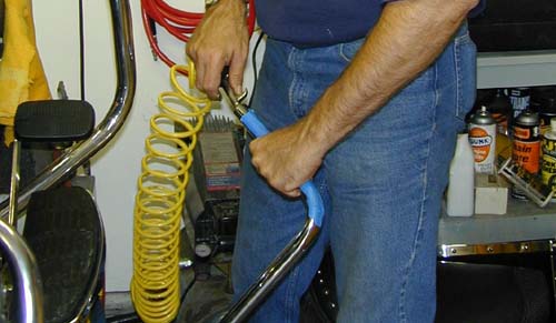
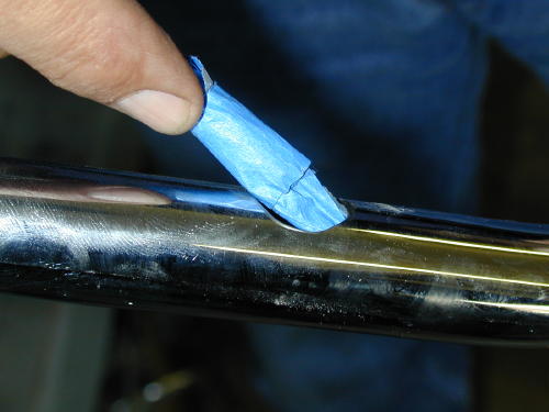
I used a painters masking tape to wrapthe connections and form a guiding point. Ididn’t want to use a tape that would requireawkward or violent stripping to remove it(which could damage the wiring).
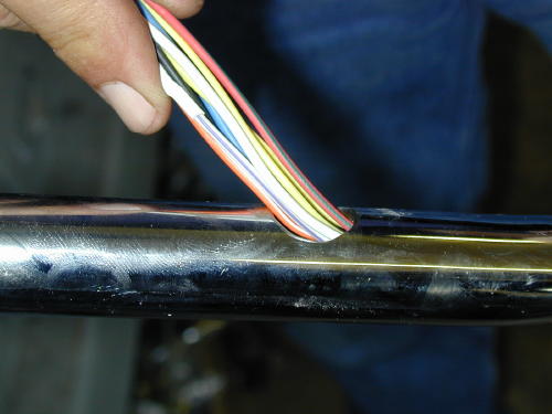
Feeding the wiring into the bars fromthe grip end.
Once carefully pulled through the bars andthe switch housings positioned, we beganthe process of installing the connector pins.
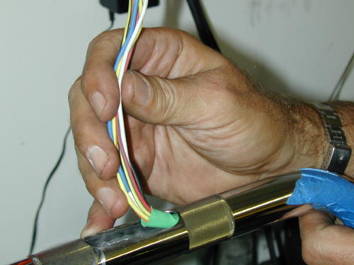
Gently pulling the wires from thebottom of the bars.
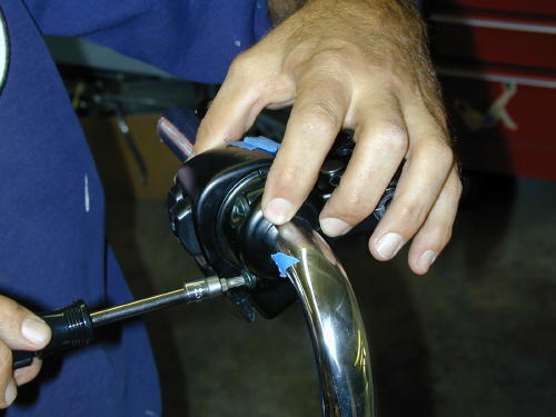
After making sure the wires are exactlyin the right position we snugged down the torxscrews, but not permanently.
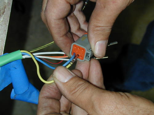
While refering to the diagram on thebench we carefully replaced the wires in thebottom of each plug.
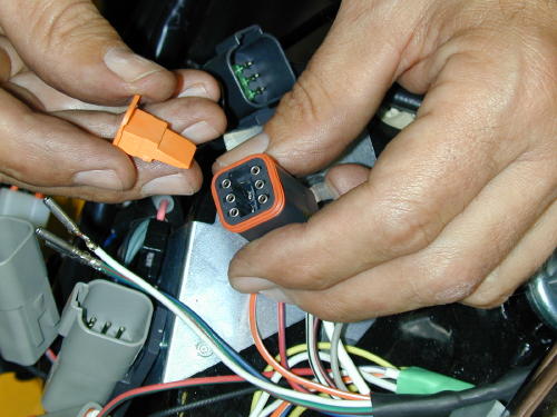
Note the wedged caps that force eachwire clip into a locked position.
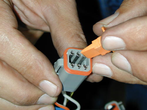
This depicts the same procedure fromthe other side of the bars. What a great shot,huh?
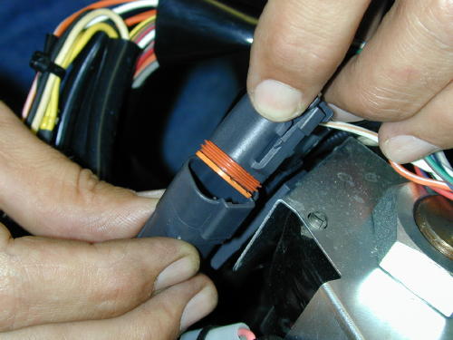
Only then could we snap the plug backinto place on the bike. Of course the plugcolors matched.
This was a nervous time. We hadextended 8 and 9 wires respectively (on eachside of the bars), carefully worked themthrough the bars and guided them out thebottom. As we replaced the plugs the sweatbeaded on my brow. Had I correctly solderedeach wire? Was each wire replaced in theplugs properly? Did I call a wire white withgray stripe, when it was actually white withblue stripe? It had taken almost four hours tocomplete the operation on the left side of thebars.
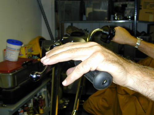
We put the levers in place just to checkthe position and see if we didn’t blow it. It wascool.
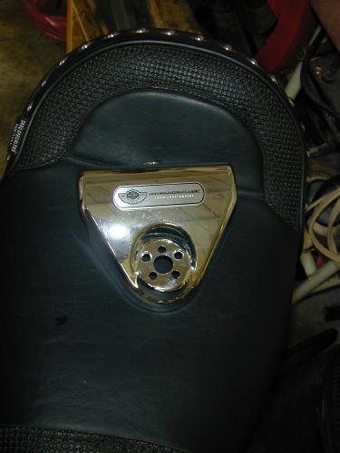
After a needed lunch break we tackledthe right side of the bars with the sameprocedure. Now with the wiring installed in thebars they were returned to the motorcycle. Iswung my leg over the 100th anniversaryCobra-styled seat and perched my ass down.Frank turned the ignition switch on, “try it out,”he said.
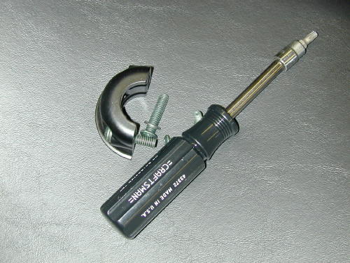
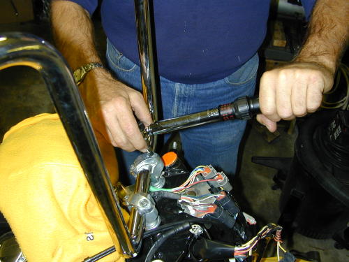
Torquing the bars down to 15 footpounds. Torque the front Allens down first,then the rear according to Pablo.
Continued On Page2
Mudflap Girl Part 4, the Spitfire Frames to Rollers
By Robin Technologies |
Suddenly we’re smoking on the Mudflap Girl FXRs, but the week after I received the frames, I had to jump a plane to New Orleans and ride a Victory to the Smoke Out. I was itching to work on these bikes.

I survived the Smoke Out, and since I just spent 1000 miles in a Victory saddle, I was motivated to get back in the wind. We looked down the barrel of the ticking calendar as I returned from the East Coast on Sunday and Monday the 27th of June I stepped back into the Bikernet shop and faced two Mudflap Girl FXRs on lifts ready to rock. I dove in making lists and started to assemble my frame and the Spitfire girder front end.

Building a bike is like falling in love. We all have our dream of the perfect woman, and each time I build a bike, that notion is the driving force. I’m building the perfect romance, with all the best intentions. I want this one to last forever, take me anywhere I want to go, and be my Mudflap girl baby in spirit, appearance, and function.

I would imagine the same mental scenario applies to a home building architect. In fact, we have focused some of our efforts on creating a vintage motorcycle coffee shop in the front of our building, Bandit’s Barista. Talk about a daunting process involving several city agencies. Let’s leave that one alone. Sin Wu came to a meeting this morning and immediately quizzyness engulfed her and she was forced to leave. “It’s too daunting,” she said.

We are so fortunate to be able to rely on our friends and compadres in this industry and build whatever motorcycle we want, then go for a ride without severe governmental restrictions. Meanwhile, back in the shop, I was completely astonished at Paul Cavallo’s talents and shop capabilities. He designed and manufactured every element of this classic girder front-end. As I installed his internal fork stops and began to assemble the front end with the Foose-designed MetalSport 2D wheel, I was constantly blown away at every intricately machined piece.

Although Dr. Willy bitched about the top motormount on the frame, I didn’t have a problem with it. It just forced us to face another brief obstacle, which will ultimately create a very cool linkage issue with a 7/16 pivoting rod end on the top like most FXRs.


But I’m getting ahead of myself. I installed the fork stops, then the Biker’s Choice neck races, the Timken neck bearings, and the Metal sport front wheel on the Spitfire ¾-inch axle. Paul set up his frames to take stock Harley 2000-2007 front and rear brakes. We are going to use factory brakes on my son’s FXR, but I’m running with GMA brakes currently manufactured by BDL.


I had to come up with a mounting system using Paul’s stock H-D brackets. It was a trick but worked out, with brass rod and steel spacers. I messed with it for a couple of hours. Ultimately the GMA caliper was centered over the MetalSport rotor and in a terrific position for bleeding.


Then I started to install the girder rockers and bronze bushings. I was careful to grease every component, and again I was impressed by the precision fit with each bushing and axle. I installed the trees on the fork stem and rolled closer to installing the girder structure. Everything just slipped together.


Unfortunately, I was missing one element of the front end, the brackets holding the shocks in place, so I shifted to something fun, installing mudflap girls on the Spitfire side panels. They make these Zeus fitting fastened aluminum panels out of street signs. The mudflap girls came from 2Wheelers in Denver, but the Arlin Fatland and Donna team is currently headed for Sturgis to the rally, which reminded me that Sturgis is just around the corner. If I had another month, we’d be riding the Mudflap Girls to the Badlands.


Next, I needed to install the rear MetalSport wheel and driveline. FXRs are tricky in this regard. The entire driveline from the engine to the rear wheel needs to be installed at the same time. We started with the swingarm, using the Custom Cycle Engineering swingarm axle and retrofit kits. Here’s what CCE says about these conversion kits.

SWING ARM RETROFIT KITS
Custom Cycle Engineering has developed a swing arm conversion kit that replaces the stock Cleve Bloc style swing arm bushings with spherical bearings. The conversion covers all the FLT and FXR models from 1980 to 2001. The swing arm conversion kit coincides with Harley-Davidson’s change from the Cleve Bloc bushing to a spherical bearing in all the 2002 and up FLT models.

The conversion over to spherical bearings in the early models dramatically changes the handling and tracking of all the FLTs and FXRs. The sticksion at the swing arm pivot is greatly reduced with the new spherical bearings. This allows for the swing arm to react quicker to any harsh road conditions, keeping the wheel in contact with the road. The use of spherical bearings also helps negate any lateral and torsional movement in the swing arm by the shear dynamics of a spherical bearing.

The swing arm bearing conversion kit is one if the positive answers to the inherent ill handling problems of the popular dresser models.

It was easy to install the new spherical bearings using our shop press and the special tool CCE provides with their kits. We pressed them into place with the CCE guide tool and red Loctite. Then we installed the swingarm on the transmission and the whole tamale in the frame, since the oil tank was out for sealing and some flat black protection. Ray C. Wheeler gave me a hand. We slipped the JIMS transmission and swingarm through the back of the frame sideways, then turned it level and aligned it with the frame mounting system. My son scored some used bare aluminum cleave blocks, and I ordered new H-D rubbers from Biker’s Choice. Watch how the rubbers and cleave blocks are mounted. They are like a small four-piece puzzle with guide pins in particular locations.


With the JIMS 6-speed transmission in place, we jacked up the trans for engine installation. With a centered Biker’s Choice front motormount bracket in place and the rubber biscuit we were ready to rock. Willie helped guide us through the process. Willie is a master with FXRs. He’s worked on bikes, and rebuilt engines and transmissions forever. He knows all the tricks.

With the driveline in place, I started to monkey with the D&D pipe mounting, mounting brackets, and mounting the GMA rear brakes. The brakes became tricky, since Paul designed a tougher and wider swingarm, but it worked out perfectly. I’ll get to that puppy in a minute. I noticed that the trans didn’t come with the final seal and locking nut, plus we needed to reach out to JIMS for a proper offset sprocket for the 180 Avon tire. Since this is an 80-inch Evo, I wanted some gearing advice for the 6-speed overdrive transmission.


Here’s what James Simonelli wrote while packing for the Sturgis Rally and preparing for their install facility. Call them quick, if you want an upgrade while you’re in town.

MUDFLAP GIRL GEARING ADVICE FROM BAKER DRIVE TRAINS–
22-51 with normal 37-24 primary is 3.57, pretty lively! In 6th (.86)
you would have 3.07
23-51 37-24 gives 3.42 and 2.94 in 6th. I think that’s where I’d start.
To compare, most stock late models with 70/32 belt and 36/25 primary are
3.15 overall in 5th.
It’s nice to be slightly below 3.0 in 6th for 75 mph cruising. If it’s a
stoplight burner, go the other way.
Baker will be set up in Sturgis on Lazelle performing installs. If you would like your 5-speed modified into a 6-speed, or a special Baker oil pan added to your dresser, set up an appointment soon, and tell ’em Bikernet sent ya.


We ordered a rear sprocket spacer and a dished 51-tooth sprocket from Biker’s Choice. It’s always somewhat a roll of the dice and I try to build a selection of spacers to allow me a variety of spacing options. With the JIMS ½-inch offset 23-tooth sprocket and the centered wheel, the transmission lined up perfectly with my brand new O-ring chain. It had never been removed from the crumbled box after a trip or two to Bonneville. I pulled it free from its container and the bastard was covered in rust.

Chad from JIMS sent me a photo of the mainshaft seal-installing tool. I also ordered the seal spacer, but had an installation question.

“Tech says bevel side faces into trans,” said Chad. “I have attached an image of the
needed tool, #786.” I dug through my special tool bins and found something from JIMS that would handle the trick.


In the meantime, our sheet metal returned from Jim Murrillo, who sealed the tanks with Caswell and gave the exterior a protective primer coat. It was a rush to slip the two gas tanks into place but we ran into a problem with my oil tank. I almost had to take the engine and the trans out of the bike to return it to its rubber mounts. Ah, but we succeeded.


Now all the major elements are in place, but the Sturgis Run is moments away. We plan to load my Sturgis Shovelhead onto our trailer, with the 120-inch Panhead, the Salt Shaker for Mr. Wheeler to ride. We will snap the trailer to the Bikernet hearse and cut a dusty trail in a couple of days. While I’m in the Badlands I’ll be thinking of Mudflap Girls and getting back to the builds. I’m sure I’ll return with more ideas, and next year will be the year of riding FXRs to the Badlands.


Hang on for the next installment as we mount up the Trock-modified CV carb on my ride, and the Mikuni 42 mm on my son’s bike. We have wiring harnesses from Wire Plus, and I have a rare intake manifold from H.E.S. and Branch, that was ported by John O’Keefe. We’ll be rolling close to final assembly as I install my BDL belt drive system and Frank’s mid controls. Goddamnit, I can’t wait.

Sources:
Spitfire
Biker’s Choice
JIMS Machine
MetalSport
BDL/GMA
Wire Plus
Branch O’Keefe
Bennett’s Performance
Custom Cycle Engineering
Road King 12/20/02 Part II
By Robin Technologies |
I couldn’t think or speak. I had a week and a half to insure that this puppy ran. I could sense fangs growing under my upper lip. I began to snarl as my fingernail extended beyond my cold hard hands. My eyes reddened, and I wanted to ride. Without the throttle cables I could use the cruise control, if it still worked. I could jam it into gear and fly. Frank hit me with a torque wrench. “We’re burnin’ daylight,” he snapped, “Let’s measure the cables and install the left Knuckle style grip.”
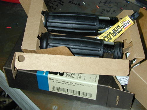
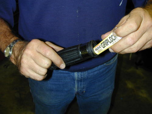
After wiping the grip end of the bar down with alcohol, the grip interior was coated with the rubber cement, that came with the grips. Then it was immediately slipped into place.
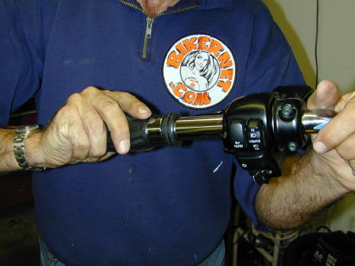
I snapped out of my Werewolf London fog. We measured the clutch cable then compared our findings with the throttle cables. As I suspected, lucky 13 inches to make up for the 12-inch taller bars that were an inch wider than the stock units. Frank made a B-line for the phone to call Barnett’s and ordered the cables. We were scheduled to roll up to the fleet center for a performance upgrade on Friday. It was Tuesday and the cables wouldn’t arrive until Thursday. It was going to be a close call. “Barnett has been around since Moby Dick was a minnow,” Frank said. I’ve been ordering custom cables from them since I was in my 20s and first influenced by Apehanger madness. “They are as reliable as the sun on the coast,” Frank continued, but I was still nervous.
We weren’t done yet. We torqued (15 foot pounds) the bars into place and began to cut and fit Goodridge brakes hoses, distributed by Barnetts and Custom Chrome. Another delicate operation.
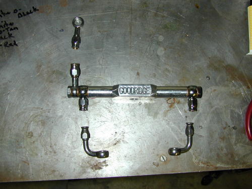
The King has dual disc brakes and the fittings had to be installed just right, tightened properly and finally torgued into place. From the bottom of the triple-trees we used the stock measurement to the calipers from the existing junction under the trees. The new lengths of Goodridge hose were cut with the largest, strongest side cutters I had. Before any fittings were installed we slipped a 2-inch piece of black 3/8-inch diameter shrink tubing over the hose. Next a chromed pinch fitting was slipped over the cable. Frank brought the tools and supplies including a tool to spread the braided hose after the rubber housing was stripped away to allow the new fitting to be installed.
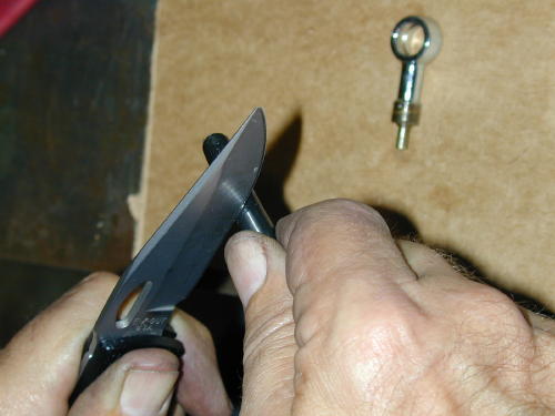
Stripping the rubber sleave back from the end about an inch.
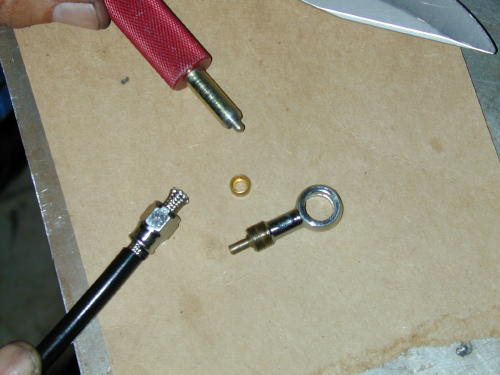
Here’s all the components involved in the process.
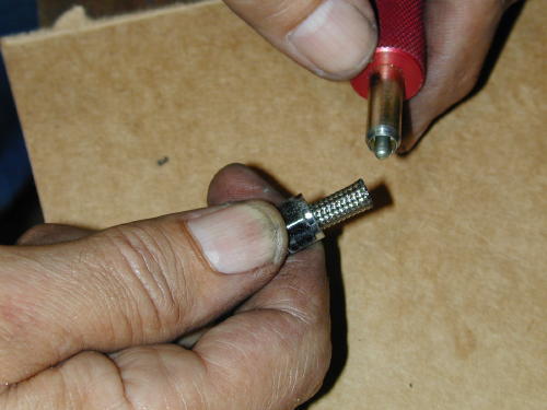
The tool used to spread the braided steel shield.
Then a small brass round furl (like a brass ball-bearing with a hole in it) is slipped over the plastic lining. It must be pushed to the point where the internal brass ridge meets with the end of the plastic liner. The other half of the fitting with the long tube is shoved into place. In each case we clamped the fitting between two sheets of leather then began to tighten the sleeve onto the fitting. In each case they were a bear to tighten down indicating that we had succeeded in a strong, secure grip.
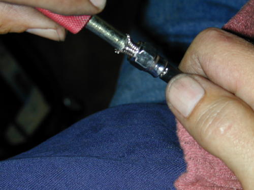
The spreading process involves shoving the tool into place and swiveling it to make sure the braided area is spread consistently.
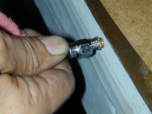
Installing the furl is simple, just slip it on carefully then push it into place. But, inspect the inside to make sure the plastic hose is against the interior ridge.
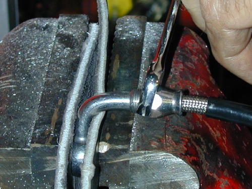
Now tighten the pinch fitting. Note the leather pads in the vice to prevent damage to the banjo fitting. These puppies are tough to tighten down, take your time.
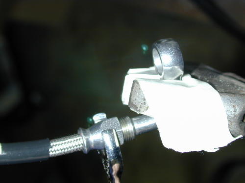
Here’s another way to hold the banjo fitting for final tightening. Be careful not to bend or damage the sealing surfaces.

Note the two bronze washer/gaskets on either side of the banjo fittings for proper sealing which is critical to your brakes.
After each line was carefully constructed, they were installed on the bike after some jockeying with the Goodridge billet junction under the tree which fit precisely.
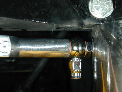
For some reason, this Goodridge junction mounted extremely snug between the fork tube guards. For awhile we thought we were in trouble.
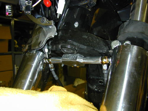
We followed the original routing of the stock brake line through the nacelle. With the lines in place we torqued them down (17-20 foot pounds). I took the easy way of bleeding the brakes. I pulled on the lever gently allowing the bubbles to pass through the master cylinder. It took a while, and I had to keep filling the reservoir as the the lines drained the supply.
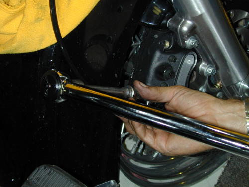
We used the stock 12-point fittings which torqued down easily to 17-20 foot pounds, which seemed like a lot.
We had completed all that was possible for Tuesday and I swung my leg over the saddle once more. As fire and smoke poured from my ears Frank crept out of the garage and into the night.
Thursday morning I paced the vast porch in front of the headquarters waiting for the UPS man. The truck sped past without a hint of slowing. I called Frank, he called Barnetts. I called the Fleet center after finding that the cables wouldn’t arrive until Monday morning, guaranteed. We had an American Rider magazine deadline, but more importantly I had a run-to-Arizona-deadline for the following Friday. I started pacing the garage and bowing to the new 16-inch apes. I knew, by the power of the Ape, we would succeed.
At 9:00 a.m. in my boxer shorts, Monday morning, I met the UPS man and signed for the Barnett package. I started to lube all the cables then decided that I should get dressed.
In order to install a new clutch cable the face of the transmission must be removed. I was surprised that this was the first item that I ran across on the King that was a pain in the ass to install. The entire exhaust system had to be loosened all the way back to the rear muffler isolator. before the clutch release housing could be removed.
With large clip ring pliers the throw-out mechanism was set free to release the clutch cable which virtually snapped into place. Then the cover was spun to allow the cable housing to unscrew. Next the new cable was fed along the same route as the stock job.
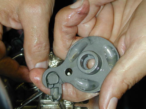
Once the clutch release cover is removed and the clip ring snapped out, you can see the outer ramp with the coupling ready for the cable.

If you look close the cable has been fed through the hole and is heading towards home.
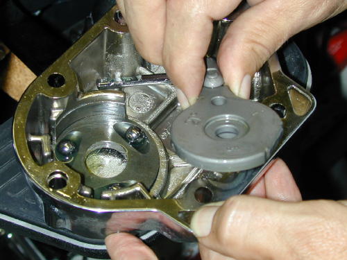
Now with the new cable attached the outer ramp heads back into position. Watch you don’t tilt the case. The ball bearings will escape.
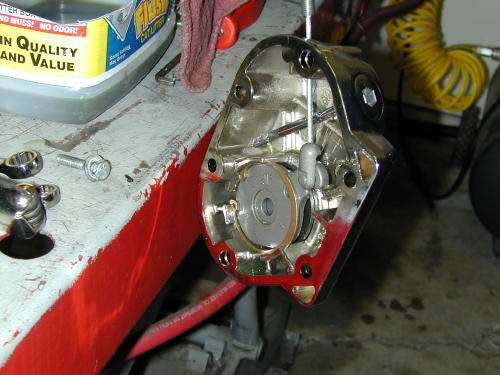
This shot shows the entire clutch release assembly complete. Remember as you reposition the clip ring to put the sharp edge up for the most secure bond.
We discovered that we had a lot of slack and rerouted the clutch cable outside the front motormount to eliminate some. Then the tranny cover gasket was wiped clean and the cover replaced (torqued to 10-12 foot pounds), then refilled with tranny fluid to the appropriate level with the bike upright and the dipstick threads just touching. We filled it to the top dipstick mark, about 3/4 of a quart capacity.
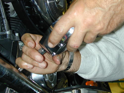
With this assembly you spin the cover onto the cable, not visa-versa.
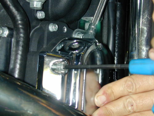
According to the book, the torque specs call for 10-12 foot pounds of torque to snug up the clutch release cover.
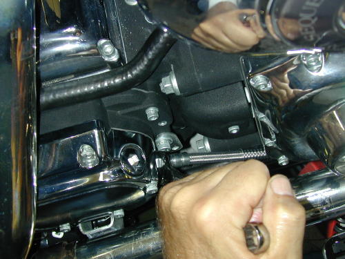
With a 9/16 box end wrench snug the cable housing down with a new o-ring attached.
We jacked-up the gas tank to afford us access to the fuel injection throttle cable routing. With the three tank mounting bolts removed the tank was lifted easily until a chunk of wood could be wedged under the front of the tank. Then I figured out which cable was what. With a small Crescent wrench, I loosened the throttle cable adjusters and took out all of the adjustment to allow lots of cable slack.
The unit with the small spring around the cable at the throttle body end was the push cable. I fed the braided cables through the runners as if they were stock cables. You will note, if you attempt this, that there is a Cruise Control connection in one of the stock cables at the neck. We unplugged it with trepidation. I wasn’t sure what havoc it would cause. I hadn’t tried the Cruise control. As it turned out, it’s a sensor to kill the control, if you back off the throttle abruptly.
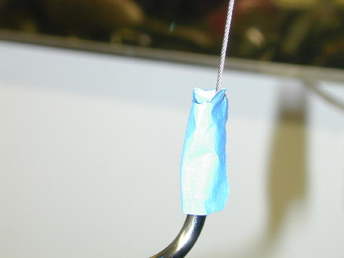
Lubing throttle cables starts with wrapping the cable housing with a little masking tape to create an oil container. Fill it with a light 3-in-1, silicone, or Marvel Mystery oil and let it seep into the housing. Fill it several times.
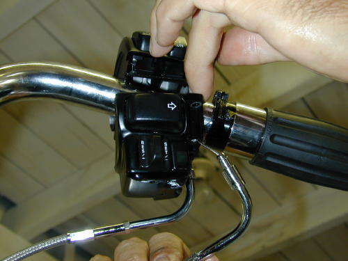
Feed the cables up through the throttle casing. With a little force they will snap into place.
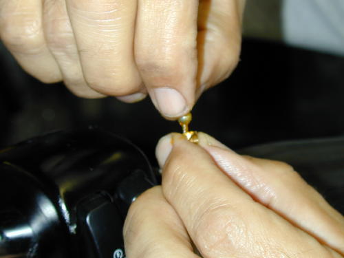
Make sure to grease the brass barrel before installing it to the cable end. The grease will help hold the barrel in place.
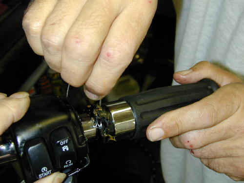
With the Barnett cable set at the most slack position, slip the barrel and cable onto the greased throttle guide grove.
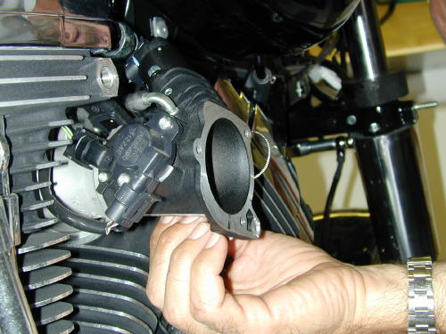
This is not a good shot of installing the cables into the guide slots in the intake module, but it’s easy. Just make sure you have the right cable in the right slot. It doesn’t hurt to grease them which we forgot.
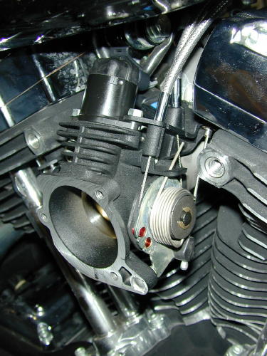
Here’s the cables in position. That odd short cable on the side is the cruise control job.
Make sure you oil the throttle cables before they are snapped into the throttle housing on the bars, because the spring clips that hold them into place are a bitch to remove. The cables were both put into place with brass rollers, “After you grease the throttle and cable runners with a Q-tip,” Frank reminded me. Be careful not to lose those tiny brass suckers. I was told later to try to adjust the cables evenly under the throttle and make sure you have slack in both lines so you don’t have continuos drag on the cable fittings.
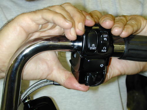
Here’s the throttle body in place waiting for the front brake mastercylinder.
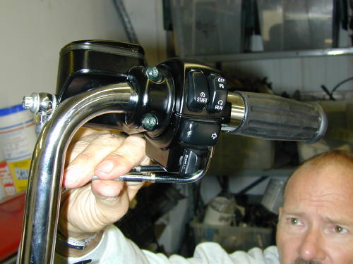
According to experts, you should adjust the cables so that the adjustment screws are approximately equal in length. My adjustment had to be straightened out at a later date.
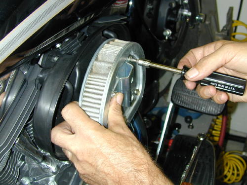
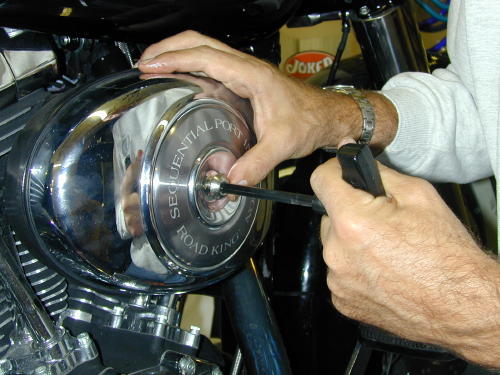
Finally we replaced the air cleaner backing plate using Phillips screwdrivers to hold the gasket in proper position. Next the breather hoses had to be pushed onto the head fittings and lined up with the air cleaner element. Lastly the cover was installed. It was time to ride.
But not so fast Kimosabe. We had to install the riser cover, the nacelle trim and the headlight assembly. We were hauling ass.
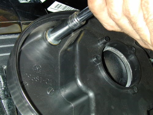
The actual breather fittings hold the air cleaner backing plate into place.
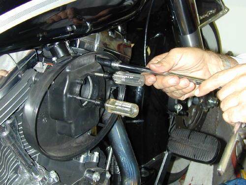
Use small Phillips screwdrivers to hold the air cleaner gasket aligned.
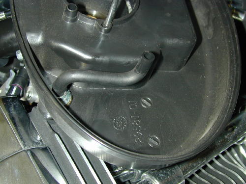
Push the hoses into place keeping in mind that they feed into the air cleaner element.
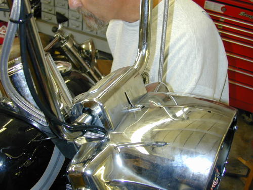
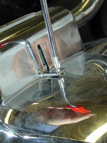
This little nut and screw are a bear to replace but must be handled before the nacelle strip can be installed.
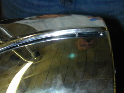
This slightly out-of-focus shot shows the little stud that slips through the nacelle. Make sure the strip is locked into the riser cover slot before you tighten the nut.
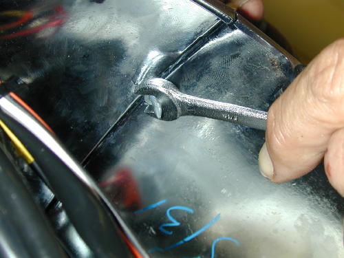
Tighten the nut lightly with blue Loctite to keep it from rattling loose.

Don’t forget to plug the headlight in before you install it, like I did.
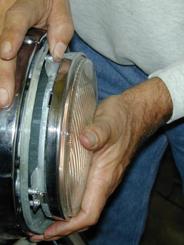
Install the headlight assembly with all eight black screws. Leave the bright adjustment ones alone, unless you lowered your bike. Then it needs adjustment.
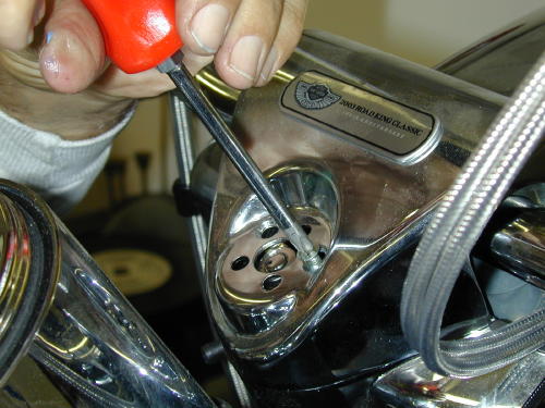
We could screw the riser down with the Phillips screws and replace the snap-on ignition ring last. I still don’t like the way it fit and need to check it again.
By noon on Monday we had completed the Highbar installation and I was itching to hit the road. We had moved our appointment at the fleet center from Friday to Monday morning, then to Monday at noon. We didn’t roll up to their doors until 1:30 p.m. and Alan, the master mechanic announced that he was leaving at 4:00. We were burnin’ daylight once again. Would the pressure every end?
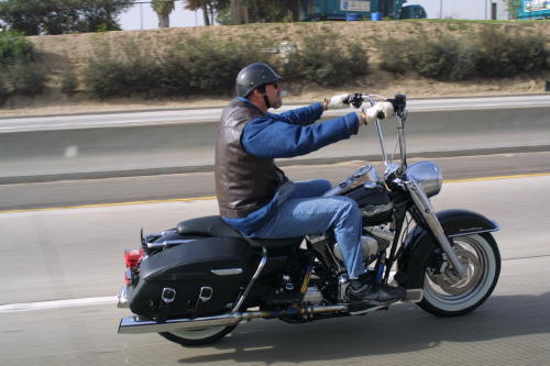
The final Frank shot with one hand hanging outside of a van window. I want to thank Frank for the use of his tools and his photographic and technical skills. Those elements and my bumbling hands make these techs as complete as they are. Believe me, it’s a bastard to build a bike, write a tech and take the shots at the same time. We’ve done it before, but a team efforts helps a helluva lot.
Next, we’ll install a performance package with Screamin’ Eagle heads, cams, air cleaner and two into one exhaust that we had jet hot coated. Hang on.
–Bandit

