READY TO LIGHT THE FIRE AND HAUL ASS!
Waitin’ on the call from San Jose?

We started getting serious in January of this year. A table full of top shelf parts we’re staged in Signal Hill, ready for a serious build. In my last episode we covered the bottom end build. We just needed the engine finished. Then I could blast to San Jose and deliver it to Ron, at Hardtailz. Shortly thereafter, I would hopefully be on the road again, then we could devote all our Bonneville space on my 124-inch 5-Ball Raycer.

Eric Bennett at Bennett’s performance cleared his engine building bench and the rest is nearly history. Eric was kind enough to stay late more than one night working on this build. Our next move included the new RevTech 97-106 top end performance upgrade. It was perfect for this project.

But, without the proper tools the job would be one helluva lot more time consuming to say the least. Tools are mandatory and quality counts. JIM’s Machine has damn near every speciality tool you might need. Ben at Rivera has a wide selection of speciality tools also.
Step up and pay the price for the proper tools and they will last a lifetime/guaranteed. Says so on the box, must be true. Since I’m new at this tech writing gig, and I was out of reach while Eric slaved away night after night, between practice sets with the Signal Hillbillies (a music studio graces the back of his shop), I reached out to Brad Beach at Custom Chrome for the official top end build instructions.
Specialty Tools Needed
• Harley Davidson service manual for the specific model you are working on
• Piston ring compressor
• Piston ring expander
• Piston ring end gap filing tool
• Digital or dial calipers
• Feeler gauge
• Torque wrench

After all of the votes were counted, re-counted and confirmed, after a night in the Cantina sippin’ whiskey with the frisky dancin’ girls, we decide on a 97-inch CCI kit while searching for the holy grail of motorcycling, in-town crisp, and responsive with handling, and stopping issues addressed, and longevity for the long road as well as bullet proof performance in a solid foundation. Not asking for much are we?
I actually wanted to go for the 106-inch kit, and even tried to make a secret call to Dark Horse, who rebuilt the lower end. Bandit pushed for a reliable 97 inches, while I would have slipped in a 96-inch lower end, and when Bandit wasn’t looking bolted up a turbo. I can’t help myself.

With the majority of the parts in one town Eric started the assembly process by measuring and setting the ring gap to Revtech specs. The follow tech info comes generally from the CCI kit instructions written by Brad.
A) Setting Ring End Gaps

Notes
• Each ring should be fitted to the cylinder in which they will be installed.
• Never alter the end gap on the oil expander ring.
• Always install the ends of the expander
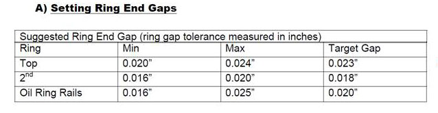
Suggested Ring End Gap (ring gap tolerance measured in inches)
Ring Min Max Target Gap
Top 0.020” 0.024” 0.023”
2nd 0.016” 0.020” 0.018”
1) Thoroughly wash cylinders with hot soapy water, then wash with brake cleaner and wipe with white towel. Repeat process until towel does not show evidence of debris and apply a light coat of oil immediately.
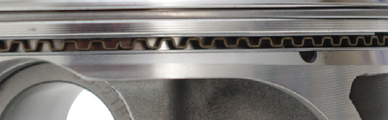
2) Check the ring end gap by placing the ring into the cylinder. Use piston or caliper to ensure that the ring is place squarely in the bore, as seen in PICTURE 2.

3) Measure the ring end gap with a feeler gauge, as seen in PICTURE 3.

4) See ring end gap table for proper ring end gap measurement. If adjustment to the end gap must be made, use a proper ring end gap filing tool.
5) Always face ring towards the inside diameter to avoid damaging the face coating while filing.
6) Remove material from only one end of the ring.
7) Ensure the ring end gaps are square.
8) Remove any sharp edges or burrs.
9) Recheck gap measurement and adjust if necessary.
Order of installation
1) Oil ring expander
2) Oil spacer rings
3) 2nd ring
4) Top ring
1) Install oil ring expander to the bottom groove of piston. Make sure the end of the expander ring is butted together and not overlapping.
2) Install spacer rings, make sure the dimple is facing down. The spacer rings are the thinnest of the rings. Install one ring above the expander and one below. Orient the ring end gaps according to PICTURE 5.
3) Install 2nd ring. Use a ring expander to install the ring to the 2nd groove in the piston. Orient the ring end gap according to PICTURE 5.
4) Install top ring. Use a ring expander to install the ring to the top groove in the
piston. Orient the ring end gap according to Picture 5.
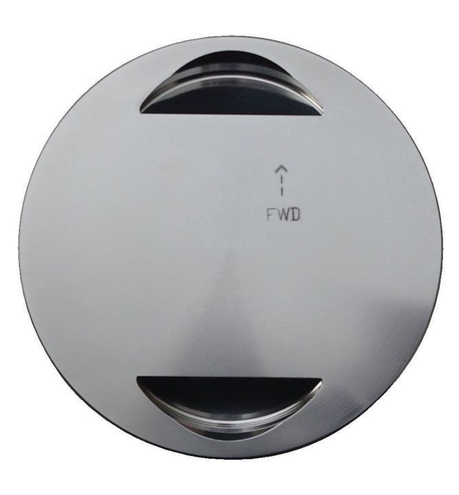
• Pistons are identical and can be installed in either cylinder. Each piston is
stamped “FWD” and has an arrow which must point toward the front of the
engine when assembled.
• Check piston pin clearance. Clearance should be between 0.0007” and 0.0012”. Bushings should be replaced if clearance exceeds 0.002”
1) Place rubber tubing over the cylinder studs to prevent damage to the pistons and rings during installation.
2) Place a clean sheet of plastic over the crankcase opening to prevent anything from dropping into crankcase.
3) Install one spiral retaining ring into each one of the pistons. Before installing the retaining rings grasp both ends of the retaining ring and stretch them apart. Make sure the retaining rings measure 1/2 to 3/4-inch unsprung.
4) Lightly oil piston pin, piston pin bore and upper connecting rod bushing with the assembly lube supplied with kit.
5) Hold the piston over the connecting rod with piston facing the correct direction and line up piston pin bore with the upper connecting rod bushing bore.
6) Install the piston pin through the piston pin bore and through the connecting rod bushing until pin contacts retaining ring.
7) Install other spiral retaining ring. Ensure both retaining rings are fully seated.
8) Repeat procedure for rear piston.
1) Bring front cylinder to TDC.
2) Apply light coating of assembly lube, supplied with kit, to the piston and rings.
3) Install the base O-ring on cylinder.
4) Lightly oil the new O-rings for the lower cylinder deck alignment dowels and install.
5) Verify that the ring end gaps are oriented correctly, according to PICTURE 7.

6) Remove the rubber tubing from cylinder studs.
7) Compress the piston rings with ring compressor.
8) Install cylinder on piston.
9) Remove ring compressor.
10) Remove plastic sheeting covering crankcase.
11) Slide cylinder down until seated against the crankcase.
12) Rotate engine until the rear cylinder is at TDC.
13) Repeat procedure for rear cylinder.
E) Cylinder Head Installation
1) Check cylinder head and cylinder gasket surface for flatness and any imperfections.
2) Check all hardware for defects. Clean all threads. Lubricate threads with a tiny amount of anti-seize. Lubricate the underside flange of the head bolts with clean oil, wipe excess oil away.
3) Clean gasket surfaces with brake cleaner and a clean rag. Do not spray the brake cleaner on the gasket surface.
4) Place head gasket on the cylinder and line up dowels.
Notes
Do not install cylinder head alignment dowel O-rings with the Cometic head gasket.
5) Check head gasket on cylinder, make sure it is not smaller than the bore of the cylinder.
6) Install cylinder head. Check brass rivets on the head gaskets to ensure the rivets do not interfere with the sealing surface in any way.
7) Install head bolts. Long bolts go on pushrod side of head and the short bolts
go on the sparkplug side.
8) Alternately snug head bolts finger tight.
9) In sequence tighten all head bolts to 9 ft-lbs. Then in sequence tighten all head bolts to 14 ft-lbs. Again in sequence tighten all head bolts to 22 ft-lbs. Then in sequence tighten all head bolts to 35 ft-lbs and finally torque all head bolts to a final torque of 42 ft, lbs in sequence, according to picture 8.
Assemble the remaining items according to the Harley Davidson manual specific for your motorcycle. Once assembly is done, the bike must be tuned properly before the break in procedure can begin. Refer to owners manual for proper break in procedure.
1) Initial start up. Run engine for 1 minute at 1250-1750rpm. DO NOT CRACK THROTTLE or apply any load to engine. The head gaskets are more prone to failure at this time. Check oil pressure.
2) Shut off engine and let cool to room temperature. Check for any leaks.
3) Start up engine again and allow to run for 3 to 5 minutes at 1250-1750rpm, DO NOT CRACK THROTTLE or apply any load to engine. Shut off engine and let cool to room temperature. Check for leaks. Repeat procedure 3 or 4 more times.
4) After engine has been cooled to room temp, you are now ready to start the 500 mile break-in procedure.
5) The first 50 miles do not exceed 2500 rpm. Avoid lugging the engine, riding in hot weather, and riding in traffic. Vary the engine speed; never ride at the same rpm. It is recommended to change the engine oil after the first 50 miles.
6) The next 500 miles do not exceed 3500 rpm or 60mph. Vary the engine rpm constantly. Do not constantly ride at the same rpm or same speed. It is recommended to change engine oil after the 500 mile mark.
7) For the next 500-1000 miles the engine can be run normal but on the conservative side. You can be a little more aggressive on the engine rpm range. The bike can be operated at highway speeds. Avoid overheating, lugging the engine, or putting an excessive load on engine, example: dyno runs, side car,
drag racing, etc.
8) After 1000 miles, change the engine oil. The motorcycle can now be operated normally.
Oil Recommendations
Revtech recommends using Revtech MTP 20W-50 synthetic oil.
The break in procedure can be performed with conventional oil but it is recommended running the oil that will be run for the normal engine operation. Use oil designated for air cooled motorcycle engines only and utilize the viscosity suggested
VISCOSITY AMBIENT TEMPERATURE
SAE 20-50 ABOVE 30-100 Degrees
SAE 50 60- 100 Degrees
SAE 60 ABOVE 80 Degrees

If you’ve made it this far and your peepers haven’t slammed shut, CONGRATULATIONS, you have earned and deserve at least one piece of freshly baked raisin pie, with all of the trimmings fresh out of the Bikernet kitchen.
Stay tuned and expect massive reports on a schedule, to be determined once the ride commences. My hearts skips a beat just thinking about cruising the highways and blistering the blacktop one more time on a happy hot rod.

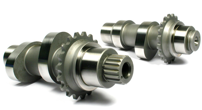
Once Eric Bennett of Bennett’s Performance installed the Branch/O’Keefe massaged heads, top shelf valve train components were next in line, with Fueling Reaper series cams. Eric installed a set of Fueling Race Lifters followed by a set of Crane Roller Rockers with a precision-machined billet support. Fueling Race Pushrods and pushrod tubes after adjusting the pushrods per Fueling directions. Properly adjusted pushrods are mandatory for a happy engine. The rocker boxes were checked for flatness then installed and properly sealed to keep the slippery stuff inside, rather than outside or on your next ex-wife’s favorite pair of boots. Oh Shit! No oil leaks will save your ass every time.

After Eric completed his piece of the build the like-new Twin Cam was loaded in the back of my Ranger for the trip North. Once in San Jose, Ron Williams and his crew made a list and checked it twice. Seems we were missing a few loose nuts? What else is new? Plus a TOP SECRET-Proto-Type throttle body was thrown in the mix for road testing. The son-of-a-bitch has NO BUTTERFLY. You will see it first on Bikernet. They installed a hot new set of Samson blacked-out, slash cut, bad-ass, baffled, performance drag pipes for waking up the neighbors. Ah, but I don’t do that…

After a few heat cycles in San Jose Friday or Saturday, an oil and filter change, then we’ll ride and file a report as soon as Saturday evening for the Cantina Sunday Post.

The call came in this morning from San Jose.
The Top Secret Throttle body now has the missing hardware needed for final installation, the starting line is within sight. After a Friday afternoon appt. at the local VA and an easy evening in front of the fireplace, without a fire. I plan on jumpin’ out of bed just after 6 AM Saturday and hauling ass north, destination San Jose and a date with my favorite sweetheart named Dyna.

Once the hot rod Dyna is rollin’ we’ll file reports on all systems from fender to fender. Hop on and enjoy the ride to roads unknown, on some rides there is a direction and an eventual destination in mind. You might be surprised. Surprises me every time.
Haul Ass!
Ride for your Life!
–Ray c wheeler
Performance Editor
wheeler@bikernet.com
CCI
Jr. Product Line Manager
Morgan Hill, CA

Bennett’s Performance
www.bennett’sperformanceinc.com
![]()
Branch O’Keefe
www.BranchOkeefe.com
Darkhorse Crank Works
www.darkhorsecrankworks.com
HPI
www.HorsePowerInc.net

Fueling Parts
www.FuelingParts.com

R&R Cycle
www.cart.rrcycles.com

Custom Chrome
www.customchrome.com
![]()
Race Tech
www.racetech.com

Hardtailz
www.HardtailzHD.com

Hyperformance
www.Kingofcubes.com

Harley-Davidson
www.Harley-Davidson.com
Thanks to all of the Craftsman and Companies many times over for sharing your professional advice and experiences mixed in with pinpoint suggestions throughout the build.
