
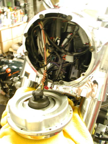

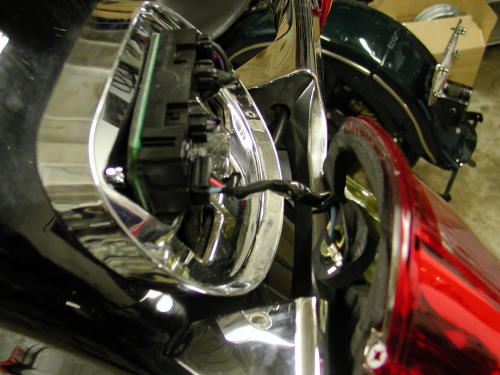
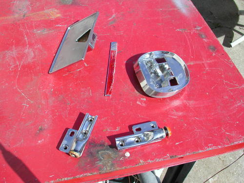
The nacelle came off with the four dome nuts that hold the detachable windshield, but when we looked at the chunks of chromed steel we came face to face with the rubber mounted brass fasteners that hold in the headlight. With a little twisting and tugging they came away from the case.
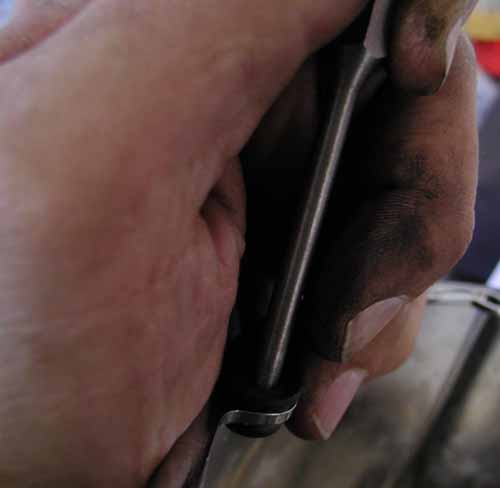
There were fastener locking tabs in the front fender which were a bear to reach and punch away from the hex head bolts. Yeah, I know, this photograph sucks, but we had to use it to show the locks.
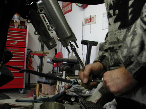
We removed the wheel first. Not so fast. I had to unbolt the calipers first and discovered the 12-point metric sockets. Everything on that Showa front end was metric even the Allens on the bottom of the lower legs. One was easy to reach, the other a pain in the ass. I needed a long metric Allen.
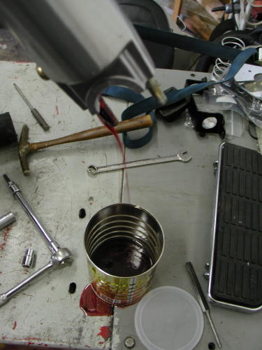
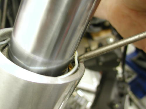
Here’s a quirk. The lower legs were drained of 11.1 ounces of front end lube. I thought that the lower legs would just slide off. Not so. You need to remove the seal retaining rings then off come the lower legs popping the seals free. We were forced to replace the seals.
I removed the two screws that hold the taillight lens in place. There’s a junction box behind the taillight held with one large 1/4-20 Phillips screw. The plugs for the turnsignals all snap out of the junction box. The box came loose easily, but the chrome taillight ring was stuck. I thought for sure there were fasteners on the inside of the fender. Not so kimosabe. It was just stuck with an adhesive pad. Once loose we discovered that it was plastic along with the rear fender tip–can’t go to powder coat. We had to sand (wet and dry 600) and paint those elements ourselves.
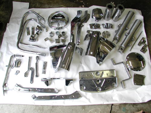
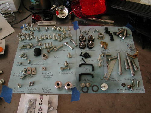
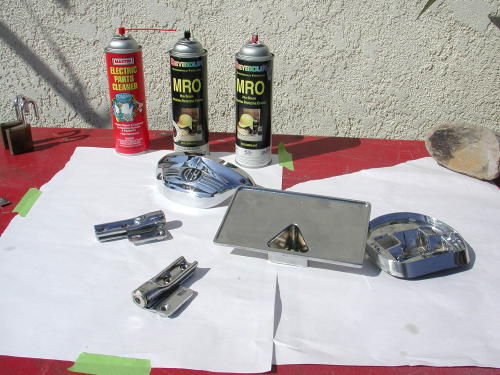
After all the parts were removed, we laid them out and took a picture of the lot for an inventory. Then each component was carefully wrapped in bubble wrap and boxed. Powder coating would take a couple of weeks. We also wrote up an inventory for Custom Powder Coating and made a copy for ourselves. I looked longingly as the UPS man hauled the heavy carton away with more than 80 parts inside.
We nabbed Custom Powder Coating as a sponsor because several of the staff are large fans of powder coating when building custom bikes. We’ve discovered that if we can build a frame clean enough, we can have it powder coated for a strong, resilient finish at a fraction of the cost of custom painting. There’s other benefits. If you want you’re sheet metal painted by someone in Tim-buck-too, you don’t have to ship the frame, wheel rims and brackets to the high-buck artist. Have them powder coated and send a sample of the finish to your creative-one.
We recently used this formula with a Shovelhead being built at Strokers Custom Bikes, formerly Dallas Easyriders. Rick Fairless who owns Strokers turned us on to Custom Powder Coating. The painter for the project is Harold Pontarelli of H-D Performance out of Vacaville, California. We sent the sheet metal to Harold and the frame and hardware to Steve Marts of Custom Powder coating in Dallas (214) 850-0011.
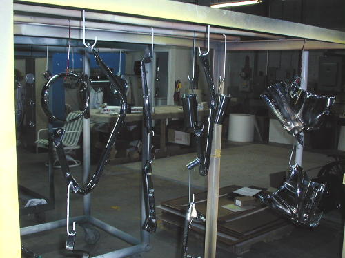
Amazing shots from Custom Powder Coating in Dallas. Are we good or what?
Steve has been in the custom coating industry for nine years. For 15 years Steve has had the dirty job of coating patio furniture. Steve and his wife Debbie prefer to run a job shop capable of coating hockey goals to bike frames. They can coat dragster bodies up to 20-feet long. Their oven is 6 feet high, 6 wide and 22 feet long. They coat four-wheeler valve covers by the thousands. They coat frames for American Iron Horse and they can virtually match any color using Prismatic Company powders that are dry blended in the Custom Color blending house. Send a swatch to match colors and they can rock.

When I asked about chromed parts Steve said, “If the chrome is fresh and new we brush blast it for proper adhesion and powder coat the part. If the chrome is flaking or old we’ll take it to a chromer to have it stripped.”
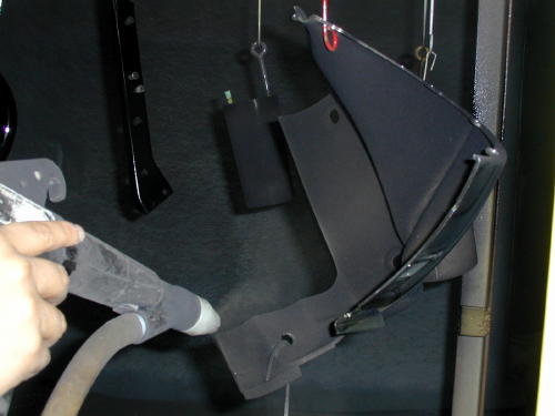
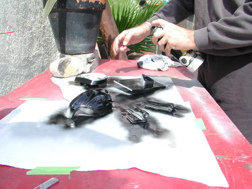
Electrically charged parts were sprayed with the powder of our choice–black, before being baked.
As an indication of the toughness of powder coating Steve discussed removing it. “It’s a bitch,” Steve muttered, “It’s so strong you can’t sandblast it off so I heat the parts to 750 degrees and it rolls into balls and runs off. Then I can blast the remaining finish.” Unfortunately, that process won’t work on some aluminum, “It will burn,” Steve added.
Okay, so here’s the basic process. Keep in mind that if you need bondo, you can’t powder coat. Bondo can’t handle the heat. Although, there is a filler now available that will take powder. Make sure all the bearing races are removed. Strip the parts as much as possible and clean them for the best adhesion. Bad welds will be smoother, but they’ll still be bad. We discovered that malady when we built the blue flame. The frame looked terrific powder coated metallic blue, but my welds still sucked. I finally coughed up the cash for a MIG welder. On the other hand we had the frame back in a week and were assembling the bike while Harold poured his magic on the sheet metal. The powder coated frame made all the difference in the timing for the ride to Sturgis. Steve recommends giving him two weeks to run through the process. He runs two shifts a day for four days a week. Only one shift on Saturdays.
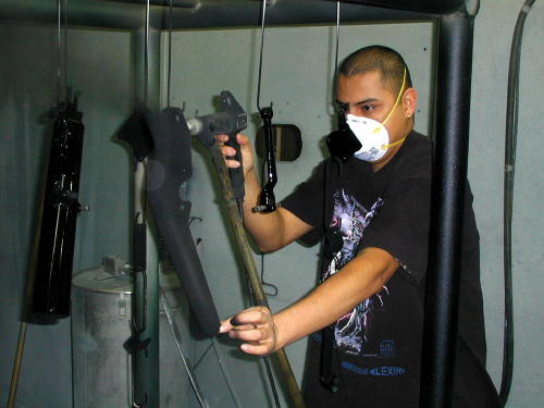
Masking is the first process after cleaning, sandblasting or bead blasting. Then the part is prep sanded. Steve has discovered that the powder holds better if the part is warmed prior to the powder painting process. With the pre-heated part the paint immediately begins to melt and doesn’t flock on the component.
Each part is powder coated twice and sometimes three times. There is a base, translucent for metallic, candy’s, and clear for depth and protection.
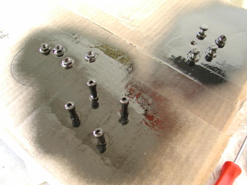
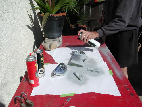
During the long day, while parts were away, we took turns taking fasteners off the diagram paper, sticking them in a sheet of cardboard and spray painting the heads with a heavy industrial gloss black.
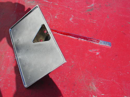
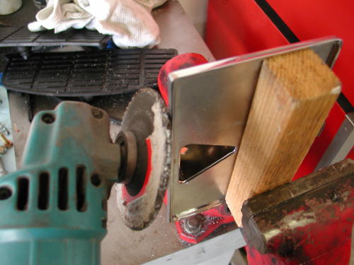
We ordered the new fender mounted license plate bracket, but when it arrived it had a long strip of reflective tape along the bottom. That 1/2-inch of metal had to be removed with a hacksaw, filed flat then wet and dry sanded. Then we sanded the chrome finish with 600 wet and dry and painted it with heavy gloss black.
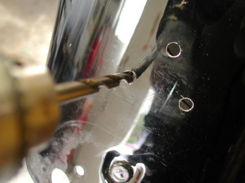
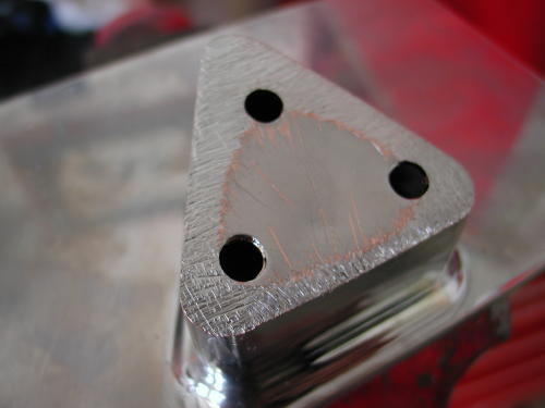
Drilling holes in the fender for the new license plate bracket.
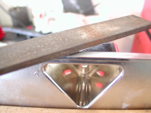
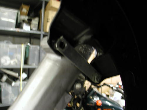
We needed to reshape the fender bracket. It was designed to be installed against the curve of the fender above the taillight, but we moved it below the taillight.
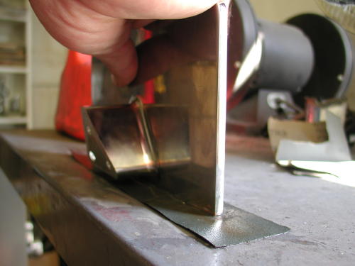
We used a two-part metal painting process for best adhesion.

Ah, that bastard brake pedal. We finally pried it loose, cleaned it with solvent, sanded it and painted the sucker ourselves.
The mag wheels were mounted with Avon Venom tires with a 150 strapped to the rear rim. The Tires were balanced and we installed the new floating rotors with black centers. My plan was to add a taste of color to the wheels with pinstriping. We discovered that the 150 was a tight fit for the King. It seems that later model Softails and Dynas are set up for 150s with narrower belts, not Touring models. We had to space the pulley away from the wheel .150 inch. Even then is was close. A bikernet reader suggested that we machine the brake caliper bracket .250-inch and add that amount to the left side wheel spacer. Pablo from Charolette H-D said that the rear wheels are slightly off center, but the manual calls for the front and rear wheel to be in line. I’m investigating further. We also discovered a problem with pinstriping the wheels. The new H-D cast mag wheels are aluminum. My striper, George, told us that the striping won’t last. Another source said that if I stripe then clear it will hold. Still investigating.
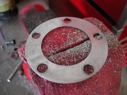
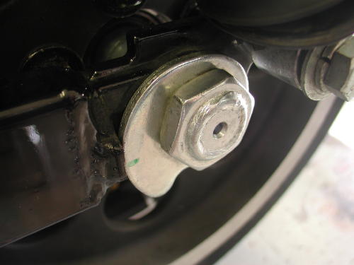
Here’s one of the spacers we used which is about .050. It wasn’t enough. Not even close.
Here’s a shot of one of the new rear axle adjusters that pull the larger axle back simultaneously. It’s not easy though. I had to set the bike on the ground as I tightened the right side, but I had to hold the left side in place or the belt adjustment changed.
An American Rider deadline was looming ahead when the UPS man knocked on the door and announced the arrival of the massive powder coating box. I was relieved to have all the parts back. I removed the spoked rear wheel by snapping off the axle clip ring with a small flat bladed screwdriver and loosening the axle nut. We spun it to release the pressure on the belt (from the left side). The trick to removing the rear wheel was the brake caliper. It seemed to lodge itself between the rim and the swingarm. It took some fidgeting to free the two elements. The new mag wheel slipped into place easily. We discovered, while returning the axle into position, that we needed to insure the belt adjuster would swing passed the shock mount, or it was stuck.
We went at the installation like two kids assembling a Christmas toy. We assembled the turnsignals with a touch of industrial lube to allow the plastic reflectors to slip back into their rubber housings and into the black shells. We referred to the factory manual for torque specifications. Then I used Frank Kaisler’s wire tool (see tech tips in Wrench’s Garage) to hold the two wires in place so that I could solder the junctions. “Don’t forget to slide on 1-inch of shrink tubing before you solder these puppies,” I told Nuttboy who was fighting the other turnsignal into place with a tiny Allen wrench.
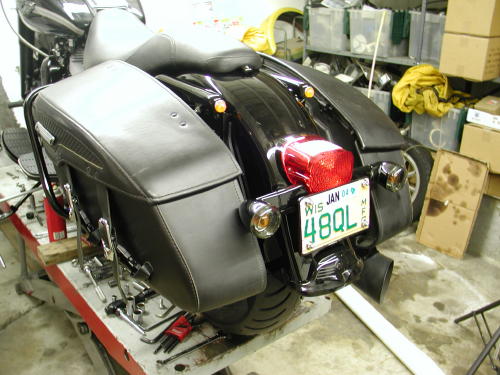
Nuttboy ground and shaped the license plate to fit the new bracket. The rear end was looking trick as we plugged the connections back together and replace the taillight. Then using copious amounts of blue Loctite we started to replace the bag roll bars, but didn’t tighten anything. We used our schematic on the bench to insure we were grabbing the correct fasteners and followed the parts from the roll bars to the fender rails. (Note: that during this process if you feel the need to remove the rear axle in the near future, don’t tighten the lower bag rail. It interferes with the axle.)
Once everything was in place, we tightened the fasteners. About the time we were leaning toward the Torx screws with a ratchet Sin Wu sauntered into the garage and pointed out a long strip of U-shaped rubber. She has a knack for timing that uncanny. The rubber strips back the saddlebag support bracket. I also noted that the long piece goes on the rear edge and the short piece on the front. Once all the elements were in place and aligned we started at the front and tightened toward the back. The saddlebag quick-release mounting brackets were also installed loose. Then we placed the leather covered bags on the bag rail and pushed the studs into place. Only then could we tightened the mounting bracket, 1/4-20, bolts. Watch that they don’t move during the last swing of the wrench. Keep them in line with the bags or installing and removing the bags will be a chore.
Continued On Page 3