Latest Articles
Toby Keith to Headline Sturgis Buffalo Chip Freedom Celebration Courtesy of the Red, White and Blue
Twenty no. 1 Billboard Hot Country Hits and 42 Top Tens make Toby Keith one ...
Big Wheel Bagger Sale, Black Friday Continues
Wana-Ryd Motorcycle, 1854-A Wallace School Rd. Charleston, SC 29407
Black Friday Deal From Suspension Technology
Black Hills Series Shocks – Save 25% Ben, Does your passenger hate riding with you? ...


New in the Cantina

Weekly News

THE FIGHTERS’ BIKERNET WEEKLY NEWS for June 26, 2025
Hey, Did you know there’s an ongoing fight to save the Sturgis Rally? Did you ...
THE CHANGING TIMES WEEKLY NEWS for June 19, 2025
Hey, We are living in truly strange times. There’s a bleak side of society trying ...

THE WHATEVER BIKERNET WEEKLY NEWS for June 12, 2025
Hey, Is life nuts or what. While 2 percent want to destroy everything, 98 percent ...

THE TOUGH BIKERNET WEEKLY NEWS for June 5, 2025
Half-Way Through the Year and Questions Continue... Hey, We are half-way through the year and ...
Tech Articles
Battistini Bagger Formula
“Back to Basics Bagger”After over two decades in the motorcycle industry I decided it was ...
Scooter’s Softail Custom Project Bike
Let me lay out the background for this project. Scooter is anattorney. Maybe that makes ...
The Devil Installs Baker 6-Speed
Click to see morefrom Lucky DevilThe Lucky Devil Metal Works shop pool. Never mind the ...
The Headlight Mystery of Light
Headwinds, the leader in custom headlights, introduces their new Black Metal headlight with Flames. Anodized ...
Bike Features

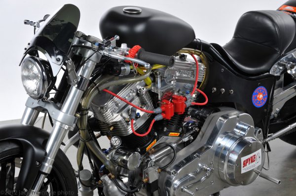
G2 Gangster-Street Legal Street Pro Bike
This is an interesting one. We met Paul Morris at the Long Beach Ultimate Builder ...
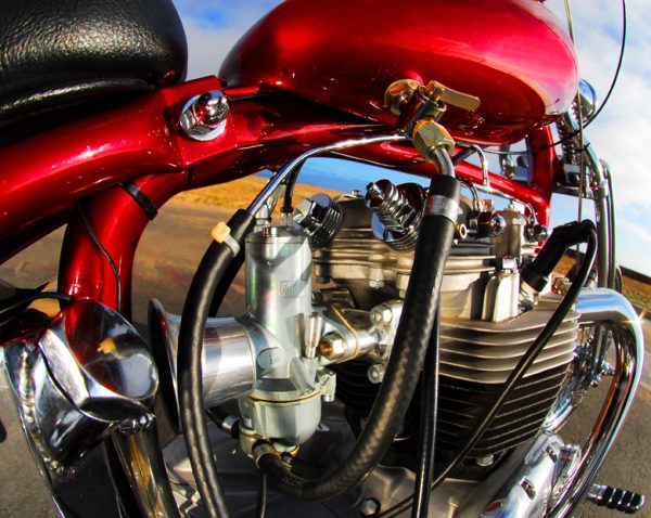
Jim’s Long-Term Classic Triumph Chopper
Some guys go through bikes like wives. Others find a bike and keep it for ...
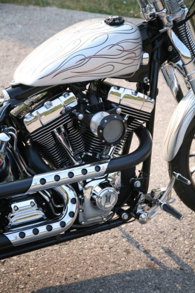
RNR Customs Canadian Streetable Softail
What the hell? I called Ryan Robinson who was rolling away from his 17-year-old shop ...
Event Features

WIN BY HARLEY-DAVIDSON RACERS JAKE LEWIS & CORY WEST
HARLEY-DAVIDSON® PAN AMERICA® ST RACERS JAKE LEWIS AND CORY WEST WIN IN MISSION SUPER HOOLIGAN ...

Roads to Redbud 2025
Hey all - anyone venturing to Buchanan Michigan on the 5th of July, for the ...

Happy Birthday ABATE Of Indiana
In the mid-seventies, the motorcycle rights movement really started in earnest. This is why many ...

AMA Motorcycle Hall of Fame Announces Class of 2025
Six distinguished motorcyclists to be inducted on Oct. 23 during the AMA Hall of Fame ...